
Related Manuals for Measurement Computing miniLAB 1008


Summary of Contents for Measurement Computing miniLAB 1008
- Page 1 1008 USB Device Analog and Digital I/O User's Guide Document Revision 3, July, 2004 © Copyright 2004, Measurement Computing Corporation...
- Page 3 Measurement Computing. Thank you for choosing a Measurement Computing product—and congratulations! You own the finest, and you can now enjoy the protection of the most comprehensive warranties and unmatched phone tech support.
- Page 4 The remedies provided herein are the buyer’s sole and exclusive remedies. Neither Measurement Computing Corp., nor its employees shall be liable for any direct or indirect, special, incidental or consequential damage arising from the use of its products, even if Measurement Computing Corp.
-
Page 5: Table Of Contents
SoftWIRE MCC DAQ Components for .NET................ 1-5 SoftWIRE MCC DAQ Controls for VB6 ................1-6 Universal Library for LabVIEW .................... 1-6 Connecting a miniLAB 1008 to your computer is easy ..........1-7 Chapter 2 Installing the miniLAB 1008................2-1 What comes with your miniLAB 1008 shipment? ............2-1 Hardware .......................... - Page 6 1008 User's Guide Adding the miniLAB 1008 to the InstaCal configuration file ..........2-9 Configuring the miniLAB 1008 with InstaCal ..............2-11 Chapter 3 Getting Started with TracerDAQ ..............3-1 Launching TracerDAQ from InstaCal ................ 3-1 Selecting the channels to use for data ................. 3-3 Configuring channel 0 ......................
- Page 7 1008 User's Guide Digital Input / Output (Screw Terminal DIO3:0)............6-3 Digital Input / Output (DB37)..................6-4 External Trigger ......................6-4 Counter Section......................6-4 Non-volatile Memory....................6-5 Power .......................... 6-5 General........................6-5 Environmental......................6-5 Mechanical........................6-6 Main connector and pin out..................6-6 4-channel differential mode ..................
-
Page 9: Preface
About this User's Guide What you will learn from this user's guide This user's guide explains how to install, configure, and use the miniLAB 1008. This user's guide also refers you to related documents available on our web site, and to technical support resources that can also help you get the most out of this device. -
Page 10: Where To Find More Information
1008 User’s Guide (miniLAB-1008.pdf – this document) Documents on MCC’s web site The documents below are available on our web site at the address specified. MCC's Specifications: miniLAB 1008 (the PDF version of Chapter 6 in this guide) is available on our web site at www.mccdaq.com/pdfs/miniLAB-1008.pdf. -
Page 11: Introducing The Minilab 1008
Chapter 1 Introducing the miniLAB 1008 This user's guide contains all of the information you need to connect the miniLAB 1008 to your computer and to the signals you want to measure. The miniLAB 1008 is a USB 1.1 low-speed analog and digital I/O device that is supported under Microsoft®... -
Page 12: Minilab 1008 Block Diagram
1008 User's Guide Introducing the miniLAB 1008 miniLAB 1008 block diagram miniLAB 1008 functions are illustrated in the block diagram shown here. Screw Terminal I/O Connector 4 Auxillary DIO Bits USB1.1 12-Bit Compliant Analog Input Interface 8 SE / 4 Diff. -
Page 13: Instacal
InstaCal is a complete installation, calibration, and test program for MCC data acquisition and control hardware. Complete with extensive error checking, InstaCal guides you through the installation and setup of your miniLAB 1008, and creates the hardware configuration file for use by your programming or application software. -
Page 14: Universal Library
Windows-based languages. When using the Universal Library, you can switch boards or even programming languages, and the syntax remains constant. The Universal Library provides the easiest way to program the miniLAB 1008. If you are planning to write programs, or would like to run the example programs for Visual ... -
Page 15: Softwire Mcc Daq Components For .Net
Components for .NET software package. In the following program, the SoftWIRE AI Scan component is configured to scan a range of channels on the miniLAB 1008 and display the measurements on a strip chart. The form on the left (... -
Page 16: Softwire Mcc Daq Controls For Vb6
SoftWIRE 3.1 and Visual Basic 6.0. With these controls, you can develop programs that read from and write to your miniLAB 1008 analog and digital channels. Example programs that demonstrate how to use the data acquisition controls are included with the SoftWIRE MCC DAQ Controls for VB6 software package. -
Page 17: Connecting A Minilab 1008 To Your Computer Is Easy
The miniLAB 1008 is plug-and-play. There are no jumpers to position, DIP switches to set, or interrupts to configure. You can connect the miniLAB 1008 before or after you install the software, and without powering down your computer first. When you connect an HID to your system, your computer automatically detects it and configures the necessary software. -
Page 19: Installing The Minilab 1008
Chapter 2 Installing the miniLAB 1008 What comes with your miniLAB 1008 shipment? As you unpack your miniLAB 1008 device, verify that the following components are included: Hardware miniLAB 1008 device USB cable... -
Page 20: Software
1008 User's Guide Installing the miniLAB 1008 Software The Personal Measurement Device installation CD contains the following software: InstaCal installation, calibration, and test utility TracerDAQ virtual instruments Universal Library data acquisition and control programming library SoftWIRE for VS .NET (fully-functional,... -
Page 21: Unpacking The Minilab 1008
Email: techsupport@measurementcomputing.com Be sure you are using the latest system software Before you connect the miniLAB 1008 and install the software, make sure that you are using the latest versions of the following software: USB driver Microsoft Data Access Components... -
Page 22: Usb Driver
Installing the miniLAB 1008 USB driver Before installing the miniLAB 1008, download and install the latest Microsoft Windows updates. In particular, when using Windows XP, make sure you have XP Hotfix KB822603 installed. This update is intended to address a serious error in Usbport.sys when you operate a USB device. -
Page 23: Installing The Minilab 1008
1008 is installed and ready to use. After the last balloon or dialog closes, the LED on miniLAB 1008 should flash and then remain lit. This indicates that communication is established between the miniLAB 1008 and your computer. -
Page 24: Installing Instacal, Tracerdaq, And The Universal Library
1008 User's Guide Installing the miniLAB 1008 If the auto-run feature is not enabled on your computer, use Explorer to navigate to the root of the CD drive, and double-click on the program. The dialog opens. Measurement Computing CD Follow the procedures below to install one or more of the software packages available from this dialog. -
Page 25: Installing Universal Library For Labview
1008 User's Guide Installing the miniLAB 1008 TracerDAQ requires the .NET Framework If your PC doesn’t have the .NET Framework installed, the checkbox may TracerDAQ not be selected. The following dialog opens if the .NET Framework is not installed and you click in the checkbox to override the default (unchecked) setting of the TracerDAQ checkbox. -
Page 26: Installing Softwire Graphical Programming
1008 User's Guide Installing the miniLAB 1008 Installing SoftWIRE Graphical Programming SoftWIRE 4.2 for Visual Studio .NET is required to use MCC DAQ Components for .NET. You must install Visual Studio .NET before you install SoftWIRE for Visual Studio .NET. -
Page 27: Setting Up The Minilab 1008 With Instacal
1008, and also to change the custom serial number. Adding the miniLAB 1008 to the InstaCal configuration file To run InstaCal and add the miniLAB 1008 to its configuration file, follow these steps. Click on to launch InstaCal. - Page 28 "If the miniLAB 1008 is not detected by InstaCal" on page 2-10. 2. Leave the check box next to the miniLAB 1008 item checked, and click The dialog closes, and the miniLAB 1008 is added to the on the PC Board List main form.
-
Page 29: Configuring The Minilab 1008 With Instacal
Trigger Source: use as the trigger source. To change the custom serial number assigned by InstaCal to the miniLAB 1008 — as part of a numbering scheme to keep track of multiple units in the field, for example — enter a number from 1 to 255 in the text box. -
Page 31: Getting Started With Tracerdaq
TracerDAQ is a set of virtual instruments that you can use to acquire and display analog data from the miniLAB 1008. This chapter details how you acquire data from the miniLAB 1008, and plot the data on the TracerDAQ strip chart. The following exercise helps get you started with the... - Page 32 TracerDAQ's virtual instruments are accessed from the View menu You can launch each virtual instrument from TracerDAQ's pull-down menu. View When TracerDAQ is launched from InstaCal, the drop-down list for the first Board plot shows the name of the miniLAB 1008 that you selected in InstaCal.
-
Page 33: Selecting The Channels To Use For Data
1008 User's Guide Getting Started with TracerDAQ Use this dialog to set up the miniLAB 1008 as the data source used by the strip chart. Selecting the channels to use for data For this exercise, you are going select channels 0 and 3 as the data source you want to acquire and plot. -
Page 34: Configuring Channel 3
4. From the list box, select Range BIP10Volts Configuring channel 3 To configure the miniLAB 1008's channel 3 as part of the data source to acquire and plot, follow the steps below. 1. Click to select the second check box. Enabled 2. - Page 35 Data Source Setup TracerDAQ – [Strip Chart] becomes active, as shown below. Use the form to set up your data log file, and to start TracerDAQ – [Strip Chart] acquiring and plotting miniLAB 1008 data.
-
Page 36: Setting Up A Data Log File
1008 User's Guide Getting Started with TracerDAQ Setting up a data log file You can log all of your data to a text file or to a Microsoft Excel spreadsheet using the TracerDAQ strip chart's dialog. When you log data, all of the Data Logging Options data acquired since the scan began is saved to a file that you specify. -
Page 37: Plotting And Logging Data On The Tracerdaq Strip Chart
1008 User's Guide Getting Started with TracerDAQ In the dialog, enter a name in the text box, and navigate to the Save As File Name location where you want to save the text file. TracerDAQ creates the file if it does not already exist. - Page 38 1008 User's Guide Getting Started with TracerDAQ TracerDAQ strip chart continues to acquire, plot, and log data until you click on the icon. An example of a strip chart data log file is shown below. To stop acquiring data, click on the icon.
- Page 39 1008 User's Guide Getting Started with TracerDAQ With TracerDAQ's virtual instruments, you can also perform the following data acquisition functions: save data source information for later use set up a trigger to control when you acquire data customize the color of plot lines, grid lines, background areas, text, and other visual...
-
Page 41: Chapter 4 Functional Details
Software paced mode In software paced mode, the miniLAB 1008 gathers data in a single acquisition or as a group of single acquisitions. An analog-to-digital conversion is initiated with a software command, and the single data point result is returned to the host. This operation may be repeated until the required number of samples is obtained for the channel (or channels) in use. -
Page 42: External Components
Consequently, the maximum burst mode rates are 8 kS/s, 4 kS/s and 2 kS/s for one, two and four channels, respectively. External components The miniLAB 1008 has the following external components, as shown in Figure 4-1. USB connector Status LED... -
Page 43: Usb Connector
Functional Details USB connector The USB connector is located on the bottom edge of the miniLAB 1008. This connector provides +5 V power and communication. The voltage supplied through the USB connector is system-dependent, and may be less than 5 V. No external power supply is required. -
Page 44: Screw Terminal Wiring
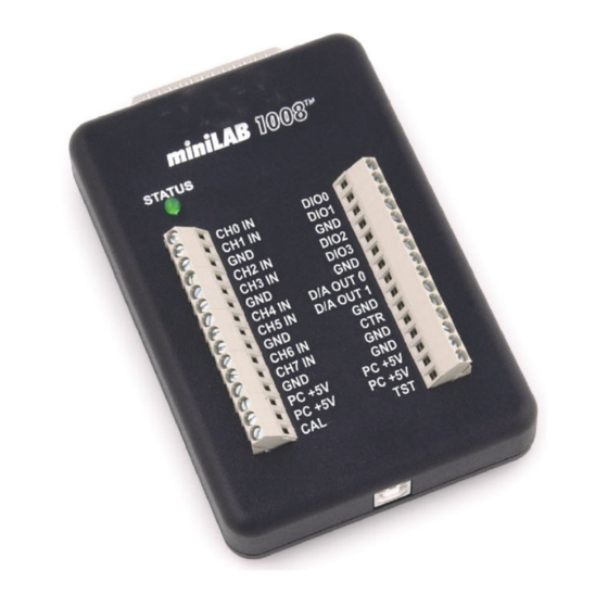
Caution! Port A0 through Port C7 have no overvoltage/short circuit protection. Do not exceed the voltage limits or you may damage the pin or the miniLAB 1008. To protect these pins, you should use a series resistor. Figure 4-2. DB37 Digital I/O Connector Table 4-2. - Page 45 1008 User's Guide Functional Details Figure 4-3. miniLAB 1008 Screw Terminals Screw terminal – pins 1-15 The screw terminals on the left edge of the miniLAB 1008 (pins 1 to 15) provide the following connections: Eight analog input connections ( CH0 IN...
-
Page 46: Main Connector And Pin Out
1008 User's Guide Functional Details Main connector and pin out Screw terminal Connector type 16 AWG to 26 AWG Wire gauge range 4-channel differential mode pin out Note that the pins are labeled for 8-channel single-ended mode on the miniLAB 1008. -
Page 47: Analog Input Terminals (Ch0 In - Ch7 In)
1008 User's Guide Functional Details Analog input terminals (CH0 In - CH7 In) Connect up to eight analog input connections to the screw terminal connections labeled CH0 In through CH7 In. Refer to the pinout diagrams on page 4-6 for the location of these pins. - Page 48 1008 User's Guide Functional Details Differential configuration When all of the analog input channels are configured for differential input mode, four analog channels are available. In differential mode, the input signal is measured with respect to the low input.
- Page 49 1008 User's Guide Functional Details Measured Signal CHHI +/-8V 8V Differential CHLO Figure 4-5. Differential voltage example: common mode voltage of 0 V If you increase the common mode voltage to 11 V, the differential remains at ±8 V.
-
Page 50: Digital I/O Terminals (Dio0 - Dio3)
1008 User's Guide Functional Details Since the analog inputs are restricted to a −10 V to +20 V signal swing with respect to ground, all ranges except ±20 V can realize a linear output for any differential signal with zero common mode voltage and full scale signal inputs. The ±20 V range is the exception. -
Page 51: Power Terminals
1008 device's USB +5 V as follows: (miniLAB 1008 @ 20 mA) + (4 DIO @ 2.5 mA ea) + (2 AO @ 30 mA ea ) = 90 mA For an application running on a PC or powered hub, this value yields a maximum user current of 500 mA −... -
Page 52: Ground Terminals
1008 User's Guide Functional Details Since laptop computers typically allow up to 100 mA, the miniLAB 1008 in a fully- loaded configuration may be above that allowed by the computer. In this case, you must determine the per-pin loading in the application to ensure that the maximum loading criteria is met. - Page 53 The primary error sources in the miniLAB 1008 are offset and gain. Nonlinearity is small in the miniLAB 1008, and is not significant as an error source with respect to offset and gain. Figure 4-9 shows an ideal, error-free, miniLAB 1008 transfer function. The typical calibrated accuracy of the miniLAB 1008 is range-dependent, as explained in the "Specifications"...
- Page 54 Gain error is a change in the slope of the transfer function from the ideal, and is typically expressed as a percentage of full-scale. Figure 4-11 shows the miniLAB 1008 transfer function with gain error. Gain error is easily converted to voltage by multiplying the full-scale (FS) input by the error.
-
Page 55: Channel Gain Queue
Figure 4-12 , we have a plot of the error band of the miniLAB 1008 for the ±10 V range. This is a graphical version of the typical accuracy specification of the product. The accuracy plots in Figure 4-12 are drawn for clarity and are not drawn to scale Input Voltage Ideal +9.77mV + 20 mV... -
Page 56: Digital Connector Cabling
BIP10V BIP1V When a scan begins with the gain queue enabled, the miniLAB 1008 reads the first element, sets the appropriate channel number and range, and then acquires a sample. The properties of the next element are then retrieved, and another sample is acquired. This sequence continues until all elements in the gain queue have been selected. - Page 57 1008 User's Guide Functional Details The red stripe identifies pin # 1 Female connector Female connector Figure 4-13. C37FF-x cable Figure 4-14. C37FFS-x cable The red stripe identifies pin # 1 Female connector Male connector Figure 4-15. C37FM- x cable...
-
Page 59: Calibrating And Testing The Device
If you calibrate only selected analog input channels, any existing calibration coefficients for channels not included in the calibration are preserved. The pin numbers and associated signals on the miniLAB 1008 are specified below for differential mode. Refer to these pin numbers when making connections to the inputs... - Page 60 This Board Calibration Channel Select dialog displays the date when the miniLAB 1008 was last calibrated. If the miniLAB 1008 was calibrated within the previous six months, it may not need calibrating. dialog automatically opens after the dialog.
- Page 61 1008 User's Guide Calibrating and Testing the Device 4. Click the button to begin calibration. The first of two Update Input dialog opens. Connections 5. Connect the analog input pins labeled CH0 IN, CH1 IN, CH2 IN, CH3 IN, CH4 IN, CH5 IN, CH6 IN, and CH7 IN to the CAL output (pin 15) and press OK.
-
Page 62: Testing With Instacal
Calibrating and Testing the Device Testing with InstaCal InstaCal provides test procedures that you can perform to verify that the miniLAB 1008 analog and digital functions are working properly. To access these tests, start InstaCal, and select the desired test option from the menu. - Page 63 1008 User's Guide Calibrating and Testing the Device status light illuminates green to indicate a successful test, and the Pass next row is automatically highlighted for the next signal test. If the status LED turns red, the test on the connection failed, and the Fail following dialog displays.
-
Page 64: Testing The Analog Functions
Calibrating and Testing the Device Testing the analog functions InstaCal provides two tests that verify that the miniLAB 1008's analog functions are working properly—a loop back test and a scan test. The loop back test is a non-paced analog input test that verifies that a single analog input is functional. - Page 65 1008 User's Guide Calibrating and Testing the Device Running a loop back test Run the loop back test to verify that a single analog input is functional. This test also verifies that the onboard signal source—such as a digital output—is functional. In this test, you wire a connection between a digital output, analog output, or external signal source, and an analog input.
- Page 66 1008 User's Guide Calibrating and Testing the Device To perform the scan test, do the following: 1. Click on the tab. The following dialog is shown configured with its Scan Test default settings. 2. Click on the button. The dialog opens.
- Page 67 1008 User's Guide Calibrating and Testing the Device Click the button to launch the utility program and display the View Data ScanView data in a table. ScanView is included with the Universal Library software. The following dialog shows the data generated from channel 0 and channel 1.
- Page 68 InstaCal – Scan Plots Click the in the upper right corner of the dialog to return to the dialog. Scan Test When you are finished testing the miniLAB 1008 analog channels, click to exit the dialog and return to InstaCal’s main form. 5-10...
-
Page 69: Specifications
Chapter 6 Specifications Typical for 25 °C unless otherwise specified. Analog Input Section Parameter Conditions Specification A/D converter type Successive approximation type CHx to GND ±10 V max Input voltage range for linear operation, single ended mode Input voltage range for linear CHx to GND -10 V min, +20 V max operation, differential mode... - Page 70 1008 User's Guide Specifications Parameter Conditions Specification Integral linearity error ±1 LSB typ Differential linearity error ±0.5 LSB typ Repeatability ±1 LSB typ CAL current Source 5 mA max Sink 20 µA min, 200 nA typ Trigger Source Software selectable External Digital: DIO0-DIO3 Input current is a function of applied voltage on the analog input channels.
-
Page 71: Analog Output Section
1008 User's Guide Specifications Table 6-4. Accuracy components, single-ended mode Range % of Gain Error Offset (mV) Accuracy at FS (mV) Reading at FS (mV) ±10 V 19.531 39.531 Analog Output Section Parameter Conditions Specification D/A converter type Resolution... -
Page 72: Digital Input / Output (Db37)
1008 User's Guide Specifications Digital Input / Output (DB37) Digital type 82C55 Number of I/O 24 (Port A0 through Port C7) Configuration 2 banks of 8 and 2 banks of 4, or 3 banks of 8 Pull up/pull-down configuration All pins pulled up to Vs via 47 k resistors (default). -
Page 73: Non-Volatile Memory
1008 User's Guide Specifications Non-volatile Memory 8192 bytes Memory size Memory configuration Address Range Access Description 0x0000 – 0x17FF Read/Write A/D data (4 k samples) 0x1800 – 0x1EFF Read/Write User data area 0x1F00 – 0x1FEF Read/Write Calibration data 0x1FF0 – 0x1FFF... -
Page 74: Mechanical
1008 User's Guide Specifications Mechanical Case dimensions 157 mm (L) x 102 mm (W) x 40 mm (H), including connectors USB cable length 3 meters max User connection length 3 meters max Main connector and pin out Connector type... -
Page 75: 4-Channel Differential Mode
1008 User's Guide Specifications 4-channel differential mode Signal Name Signal Name CH0 IN HI DIO0 CH0 IN LO DIO1 CH1 IN HI DIO2 CH1 IN LO DIO3 CH2 IN HI D/A OUT 0 CH2 IN LO D/A OUT 1... - Page 76 1008 User's Guide Specifications Signal Name Signal Name USB +5V Port B7 Port C7 Port B6 Port C6 Port B5 Port C5 Port B4 Port C4 Port B3 Port C3 Port B2 Port C2 Port B1 Port C1 Port B0...
- Page 77 Middleboro, MA 02346 Category: Electrical equipment for measurement, control and laboratory use. Measurement Computing Corporation declares under sole responsibility that the product miniLAB 1008 to which this declaration relates is in conformity with the relevant provisions of the following standards or other documents:...
- Page 78 Measurement Computing Corporation 16 Commerce Boulevard, Middleboro, Massachusetts 02346 (508) 946-5100 Fax: (508) 946-9500 E-mail: info@mccdaq.com www.mccdaq.com...
Need help?
Do you have a question about the miniLAB 1008 and is the answer not in the manual?
Questions and answers