Table of Contents
Advertisement
Quick Links
Advertisement
Table of Contents

Related Manuals for Measurement Computing Data Translation DT9857


Summary of Contents for Measurement Computing Data Translation DT9857
- Page 1 Title Page UM-25656-M DT9857 and DT9857E User’s Manual...
- Page 2 Other product and company names mentioned herein are trademarks or trade names of their respective companies. © 2017 Measurement Computing Corporation. All rights reserved. No part of this publication may be reproduced, stored in a retrieval system, or transmitted, in any form by any means, electronic, mechanical, by photocopying, recording, or otherwise without the prior written permission of Measurement Computing Corporation.
- Page 3 Page Radio and Television Interference This equipment has been tested and found to comply with CISPR EN55022 Class A and EN61000-6-1 requirements and also with the limits for a Class A digital device, pursuant to Part 15 of the FCC Rules. These limits are designed to provide reasonable protection against harmful interference when the equipment is operated in a commercial environment.
-
Page 5: Table Of Contents
Table of Contents Table of Contents About this Manual ........... . . 11 Intended Audience. - Page 6 Contents Continuous Edge-to-Edge Measurement ........57 Pulse Output .
- Page 7 Contents Tachometer Input Features ........... . . 90 General-Purpose Counter/Timer Features.
- Page 8 Contents Chapter 7: Troubleshooting ..........127 General Checklist .
- Page 9 Contents LED Status Indicators ............176 LED Status Indicators on the DT9857 Module .
- Page 10 Contents...
-
Page 11: About This Manual
About this Manual The first part of this manual describes how to install and set up your DT9857 or DT9857E module and device driver, and verify that your module is working properly. The second part of this manual describes the features of the DT9857 and DT9857E modules, the capabilities of the DT9857 Device Driver, and how to program the DT9857 or DT9857E module using the DT-Open Layers for .NET Class Library™... -
Page 12: Conventions Used In This Manual
About this Manual • Chapter “Calibration,” describes how to calibrate the analog I/O circuitry of the DT9857 or DT9857E module. • Appendix “Specifications,” lists the specifications of the DT9857 and DT9857E modules. • Appendix “Connector Pin Assignments and LED Status Indicators,” lists the pin assignments of the connectors on the DT9857 and DT9857E modules, describes the screw terminal assignments of the STP25 screw terminal panel, and describes the LED status... -
Page 13: Where To Get Help
About this Manual Where To Get Help Should you run into problems installing or using a DT9857 or DT9857E module, the Technical Support Department is available to provide technical assistance. Refer to Chapter 7 for more information. If you are outside the United States or Canada, call your local distributor, whose number is listed on our web site (www.mccdaq.com). - Page 14 About this Manual...
-
Page 15: Chapter 1: Overview
Overview Hardware Features............Supported Software . -
Page 16: Hardware Features
Chapter 1 Hardware Features The DT9857 and DT9857E modules are high-accuracy, dynamic signal analyzers for the USB (Ver. 3.0, 2.0, or Ver. 1.1) bus. Available with either 8 or 16 IEPE inputs and two stimulus waveform output channels, these modules are ideal for noise, vibration, and acoustic measurements. - Page 17 Overview − Support for IEPE (Integrated Electronic Piezoelectric) inputs, including use of a 4 mA current source with 24 V compliance voltage for AC or DC coupling. − In continuous scan mode, supports a start trigger for acquiring pre-trigger samples and a reference trigger for acquiring post-trigger samples.
- Page 18 Chapter 1 • Sync Bus for connecting and synchronizing multiple modules. • Locking USB connector. • External power supply. The key differences between the DT9857 and DT9857E modules are listed in Table Table 1: Key Differences Between the DT9857 and the DT9857E Feature DT9857 Specification DT9857E Specification...
-
Page 19: Supported Software
Overview Supported Software The following software is available for use with the DT9857 and DT9857E modules and is included on the Data Acquisition OMNI CD: • DT9857 Series Device Driver – The DT9857 Series Device Driver allows you to use a DT9857 or DT9857E module with any of the supported software packages or utilities. - Page 20 Chapter 1 − Allows you to perform single-channel FFT (Fast Fourier Transform) operations, including AutoSpectrum, Spectrum, and Power Spectral Density, on the acquired analog input data. You can configure a number of parameters for the FFT, including the FFT size, windowing type, averaging type, integration type, and so on. −...
- Page 21 Overview • DataAcq SDK – Use the Data Acq SDK if you want to use Visual Studio 6.0 and Microsoft C or C++ to develop your own application software for a DT9857 or DT9857E module using Windows Vista, Windows 7, Windows 8, or Windows 10; the DataAcq SDK complies with the DT-Open Layers standard.
-
Page 22: Supported Accessories
Chapter 1 Supported Accessories The following optional accessories are available for a DT9857 or DT9857E module: • STP25 screw terminal panel – A screw terminal panel that connects to the Digital connector on the DT9857 or DT9857E module using the 25-pin, 1.5-meter, EP403 cable that is included with the STP25 screw terminal panel. - Page 23 Overview • EP386 panel – (For the DT9857 and DT9857-OEM modules only.) The EP386 panel, shown Figure 4, contains four RJ45 connectors that are wired in parallel, making it useful when attaching up to four DT9857 modules together using the Sync Bus connector. Refer to page for more information on using this panel.
-
Page 24: Getting Started Procedure
Chapter 1 Getting Started Procedure The flow diagram shown in Figure 5 illustrates the steps needed to get started using a DT9857 or DT9857E module. This diagram is repeated in each Getting Started chapter; the shaded area in the diagram shows you where you are in the getting started procedure. Set Up and Install the Module (see Chapter 2... -
Page 25: Getting Started Procedure
Part 1: Getting Started... -
Page 27: Chapter 2: Setting Up And Installing The Module
Setting Up and Installing the Module Unpacking ..............System Requirements . - Page 28 Chapter 2 Set Up and Install the Module (this chapter) Wire Signals (see Chapter 3 starting on page Verify the Operation of the Module (see Chapter 4 starting on page...
-
Page 29: Unpacking
Setting Up and Installing the Module Unpacking Open the shipping box and verify that the following items are present: • DT9857-08, DT9857-16, DT9857E-08, or DT9857E-16 module or the OEM version of the module • EP361 +5 V power supply (not supplied with the OEM version of the module) •... -
Page 30: System Requirements
Chapter 2 System Requirements For reliable operation, ensure that your computer meets the following system requirements: • Processor: Pentium 4/M or equivalent • RAM: 1 GB • Screen Resolution: 1024 x 768 pixels • Operating System: Windows 10, Windows 8, Windows 7, Windows Vista (32- and 64-bit) •... -
Page 31: Applying Power To The Module
Setting Up and Installing the Module Applying Power to the Module The DT9857 module works with a +5 VDC power supply. The DT9857E module works with a +4.75 VDC to +28 VDC power supply. The EP361 +5 V power supply and cable is shipped with the standard version of the DT9857 and DT9857E modules. - Page 32 Chapter 2 DT9857 Module Rear Panel EP361 +5 V Power Supply Connect the EP361 Power Supply to the Module and to the Wall Outlet Figure 7: Attaching an External Power Supply to the DT9857 Module...
-
Page 33: Applying Power To The Dt9857E Module
Setting Up and Installing the Module Applying Power to the DT9857E Module To apply power to the DT9857E module, do the following: 1. Connect the EP361 power supply to the DIN power connector on the DT9857E module, as shown in Figure 8, or connect your own 4.75 VDC to 28 VDC power supply to the 3-position power terminal block. -
Page 34: Attaching Modules To The Computer
Chapter 2 Attaching Modules to the Computer This section describes how to attach a DT9857 or DT9857E module to the host computer. Note: Most computers have several USB ports that allow direct connection to USB devices. If your application requires more DT9857 or DT9857E modules than you have USB ports for, you can expand the number of USB devices attached to a single USB port by using expansion hubs. -
Page 35: Connecting To An Expansion Hub
Setting Up and Installing the Module 3. Attach the other end of the USB cable to one of the USB ports on the host computer. The operating system automatically detects the USB module and starts the Found New Hardware wizard. 4. - Page 36 Chapter 2 5. For Windows Vista: a. Click Locate and install driver software (recommended). The popup message "Windows needs your permission to continue" appears. b. Click Continue. The Windows Security dialog box appears. c. Click Install this driver software anyway. Note: Windows 7, Windows 8, and Windows 10 find the device automatically.
- Page 37 Setting Up and Installing the Module Note: If you are using a USB 3.0 hub to connect to the DT9857E moudle, be aware of the back power. The DT9857E receive power from the USB 3.0 hub when the external power supply is off and the USB 3.0 cable is plugged into the computer.
-
Page 38: Configuring The Dt9857 Series Device Driver
Chapter 2 Configuring the DT9857 Series Device Driver Note: In Windows 7, Windows 8, Windows 10, and Windows Vista, you must have administrator privileges to run the Open Layers Control Panel. When you double-click the Open Layers Control Panel icon, you may see the Program Compatibility Assistant. If you do, select Open the control panel using recommended settings. - Page 39 Setting Up and Installing the Module Power LED Figure 11: Power LED on the Front Panel of the DT9857E Module 9. If you are using multiple DT9857E modules connected together using the Sync Bus, the first and last module in the chain must be terminated with a 100 Ω resistor. Check the Sync Bus Termination checkbox to enable the termination resistor, or uncheck the Sync Bus Termination checkbox to disable the termination resistor for the selected module.
- Page 40 Chapter 2...
-
Page 41: Chapter 3: Wiring Signals
Wiring Signals Preparing to Wire Signals ............Connecting Analog Input Signals . - Page 42 Chapter 3 Set Up and Install the Module (see Chapter 2 starting on page Wire Signals (this chapter) Verify the Operation of the Module (see Chapter 4 starting on page...
-
Page 43: Preparing To Wire Signals
Wiring Signals Preparing to Wire Signals This section provides recommendations and information about wiring signals to a DT9857 or DT9857E module. Wiring Recommendations Keep the following recommendations in mind when wiring signals to a DT9857 or DT9857E module: • Follow standard ESD procedures when wiring signals to the module. •... - Page 44 Chapter 3 DT9857 Module IEPE Inputs Front Panel Analog Inputs 8 to 15 IEPE Inputs Analog Outputs 0 and 1 Analog Inputs 0 to 7 DT9857 Module Rear Panel Digital Connector Tachometer Sync Bus Chassis Power (Digital I/O, External Trigger, C/T) Input Connector Connector...
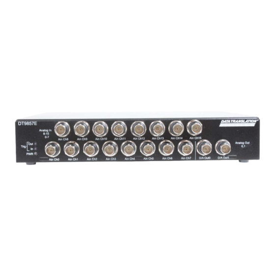
- Page 45 Wiring Signals IEPE Inputs Analog Inputs 8 to 15 DT9857E Module Front Panel IEPE Inputs Analog Outputs 0 and 1 Analog Inputs 0 to 7 DT9857E Module Rear Panel Digital Connector External Sync Bus Power (Digital I/O, Tachometer, C/T) Trigger Input Connectors Connector Connectors...
- Page 46 Chapter 3 A 25-pin Digital connector is provided for attaching digital I/O, external trigger, and counter/timer signals. Figure 14 shows the layout of the 25-pin Digital connector on the DT9857 and DT9857E modules. Figure 14: Layout of the Digital Connector To make wiring easier, you can connect the STP25 screw terminal panel to the Digital connector on the DT9857 or DT9857E module as shown in Figure...
- Page 47 Wiring Signals Shield Digital Output 7 Digital Output 6 Digital Output 5 Digital Output 4 Digital Ground Digital Output 3 Digital Output 2 Digital Output 1 Digital Output 0 Digital Ground C/T Out C/T Clock Event Output* C/T Gate External Trigger (DT9857)**; Tachometer Input (DT9857E) Digital Ground Digital Input 7...
-
Page 48: Connecting Analog Input Signals
Chapter 3 Connecting Analog Input Signals For the DT9857-08 and DT9857E-08 modules, you can connect up to eight analog input signals (or IEPE sensors) to the BNC connectors on the module. For the DT9857-16 and DT9857E-16 modules, you can connect up to 16 analog input signals (or IEPE sensors) to the BNC connectors on the module. -
Page 49: Connecting Analog Output Signals
Wiring Signals Connecting Analog Output Signals The DT9857 and DT9857E modules provide two analog output channels. The output channels have an output range of ±10 V. Figure 18 shows how to connect an analog output signal to a DT9857 or DT9857E module. Analog Out 0 Load Note that the connector automatically connects... -
Page 50: Connecting A Tachometer Input Signal
Chapter 3 Connecting a Tachometer Input Signal You can connect a ±30 V tachometer input signal to the DT9857 or DT9857E module. On the DT9857, you connect the tachometer to a BNC connector, as shown in Figure 19. On the DT9857E, you connect the tachometer input signal to pin 11 of the STP25 screw terminal panel, which is connected to the DT9857E module, as shown in Figure... -
Page 51: Connecting Digital Input Signals
Wiring Signals Connecting Digital Input Signals Figure 21 shows how to connect digital input signals (lines 0 and 1, in this case) to the STP25 screw terminal panel. Refer to Figure 16 on page 47 for the screw terminal assignments of the STP25 screw terminal panel. -
Page 52: Connecting Digital Output Signals
Chapter 3 Connecting Digital Output Signals Figure 22 shows how to connect a digital output (line 0, in this case) to the STP25 screw terminal panel. Refer to Figure 16 on page 47 for the screw terminal assignments of the STP25 screw terminal panel. -
Page 53: Connecting Counter/Timer Signals
Wiring Signals Connecting Counter/Timer Signals The DT9857 and DT9857E modules provide a general-purpose counter/timer (C/T 0) that you can use to perform the following operations: • Event counting • Up/down counting • Pulse width/period measurement • Edge-to-edge measurement • Continuous edge-to-edge measurement •... -
Page 54: Up/Down Counting
Chapter 3 Figure 24 shows how to connect counter/timer signals to the STP25 screw terminal panel to perform an event counting operation on C/T 0 without using a gate. The counter counts the number of rising edges that occur on the Counter 0 Clock input. STP25 (Connected to the DT9857 or DT9857E) Digital Ground... -
Page 55: Period/Pulse Width Measurement
Wiring Signals Period/Pulse Width Measurement Figure 26 shows how to connect counter/timer signals either to the STP25 screw terminal panel to perform a period/pulse width measurement operation on C/T 0. You specify the active pulse (high or low) in software. The pulse width is the percentage of the total pulse period that is active. -
Page 56: Edge-To-Edge Measurement
Chapter 3 Edge-to-Edge Measurement Figure 27 shows how to connect counter/timer signals to the STP25 screw terminal panel to perform an edge-to-edge measurement operation using two signal sources. The counter measures the number of counts between the start edge (in this case, a rising edge on the Counter 0 Clock signal) and the stop edge (in this case, a falling edge on the Counter 0 Gate signal). -
Page 57: Continuous Edge-To-Edge Measurement
Wiring Signals Continuous Edge-to-Edge Measurement Figure 28 shows how to connect counter/timer signals to the STP25 screw terminal panel to perform a continuous edge-to-edge measurement operation. The counter measures the number of counts between two consecutive start edges (in this case, a rising edge on the Counter 0 Clock signal). -
Page 58: Pulse Output
Chapter 3 Pulse Output Figure 29 shows how to connect counter/timer signals to perform a pulse output operation on counter/timer 0; in this example, an external gate is used. Refer to page 97 through page 98 more information about pulse output operations. STP25 (Connected to the DT9857 or DT9857E) Digital Ground... -
Page 59: Connecting Signals For Measure Counter Operations
Wiring Signals Connecting Signals for Measure Counter Operations The DT9857 and DT9857E modules provide two measure counters (C/T 1 and 2) that you can use to measure the frequency, period, or pulse width of a single signal or the time period between two signals and return the value in the analog input stream. - Page 60 Chapter 3 Figure 30 shows an example of connecting signals for a continuous edge-to-edge measurement operation using a measure counter. In this example, the signal that starts the measurement is the rising edge of the digital input signal connected to digital input 7. The signal that stops the measurement is the rising edge of the clock input signal connected to C/T 0.
-
Page 61: Chapter 4: Verifying The Operation Of A Module
Verifying the Operation of a Module Select the Device ............. . Acquire Data from an Analog Output Channel. - Page 62 Chapter 4 Set Up and Install the Module (see Chapter 2 starting on page Wire Signals (see Chapter 3 starting on page Verify the Operation of the Module (this chapter) You can verify the operation of a DT9857 or DT9857E module using the QuickDAQ application.
-
Page 63: Select The Device
Verifying the Operation of a Module Select the Device To get started with your DT9857 or DT9857E module and the QuickDAQ application, follow these steps: 1. Connect the DT9857 or DT9857E module to the USB port of your computer, and connect your sensors to the module. - Page 64 Chapter 4...
-
Page 65: Acquire Data From An Analog Output Channel
Verifying the Operation of a Module Acquire Data from an Analog Output Channel The following steps describe how to use the QuickDAQ application to monitor the output of the analog output signal using an analog input channel. In this example, a 10 V sine wave is output on analog output channel 0 of a DT9857-8 module. The analog output channel is connected to analog input channel 0 on the DT9857-8 module. -
Page 66: Configure The Analog Input Channel
Chapter 4 2. Select the Enable checkbox to enable the analog output channel on the module. 3. For the Waveform type, select Fixed. 4. For Peak Voltage, enter 10 to output a ±10 V signal. 5. For Offset, enter 0. 6. - Page 67 Verifying the Operation of a Module 4. Under the Channel Name column, leave the default channel name as Ain 0. 5. Under the Range column, select the input range for analog input channel. In this example, ±10 V is used. 6.
-
Page 68: Configure The Recording Settings
Chapter 4 Configure the Recording Settings For this example, configure the recording settings as follows: 1. Click the Recording tab of the Acquisition Config window. 2. For Filename generation, use the default Filename option. 3. For Filename, use the default name for the data file. 4. -
Page 69: Configure The Acquisition Settings
Verifying the Operation of a Module Configure the Acquisition Settings For this example, configure the acquisition settings as follows: 1. Click the Acquisition tab of the Acquisition Config window. 2. For the Per Channel Sampling Frequency text box, enter 10000. The sampling rate, sample interval, and number of scans are displayed. -
Page 70: Start The Operation
Chapter 4 Start the Operation Once you have configured the channels and the application parameters, click the Record toolbar button ( ) or press the F5 key to start the operation. Results similar to the following are displayed in the Channel Plot window, showing the output of analog output channel 0 as measured by analog input channel 0. - Page 71 Part 2: Using Your Module...
-
Page 73: Chapter 5: Principles Of Operation
Principles of Operation Block Diagram ............. . . Analog Input Features . -
Page 74: Block Diagram
Chapter 5 Block Diagram Figure 31 shows a block diagram of the DT9857 module and Figure 32 shows a block diagram of the DT9857E module. Start and Reference Trigger Sources: +5 VDC Threshold External External Return Input Power Supplies 24- bit Sync Bus Power Supply Analog In0... - Page 75 Principles of Operation Start and Reference Trigger Sources: +4.75 VDC to +28 VDC Threshold External External Return Input Power Supplies 24- bit Power Supply Sync Bus Analog In0 Clocks and Connector Software x1/10 Ain 0-7 Triggers Control (bottom board) Logic 24- bit Analog In7 x1/10...
-
Page 76: Analog Input Features
Chapter 5 Analog Input Features This section describes the following features of analog input (A/D) subsystem on the DT9857 and DT9857E modules: • Analog input channels, described on this page • Input ranges and gains, described on this page • IEPE functions, described on page 77 •... -
Page 77: Iepe Functions
Principles of Operation IEPE Functions Applications that require accelerometer, vibration, noise, or sonar measurements often use IEPE sensors. IEPE conditioning is built-in to the analog input circuitry of the DT9857 and DT9857E module. The modules support the following software-programmable IEPE functions for each analog input channel: •... -
Page 78: Analog Input Conversion Modes
Chapter 5 Once the sample clock is started, the module requires 39 conversions before the first A/D sample is valid. The valid sample is aligned with the A/D trigger. Note: The DT9857 and DT9857E modules have two power modes: low power mode and high power mode. -
Page 79: Continuous Scan Mode
Principles of Operation Continuous Scan Mode In continuous scan mode, you can acquire data from all the entries in the channel-gain list continuously. Using software, you can specify a channel list, clock frequency, start trigger, reference trigger, post-trigger scan count, and buffer using software. On the DT9857-08 and DT9857E-08 modules, you can enter up to 13 entries in the channel list: analog input channels 0-7, the tachometer input (channel 8), general-purpose counter 0 (channel 9), measure counter 1 (channels 10), measure counter 2 (channel 11), and the digital... -
Page 80: Input Triggers
Chapter 5 Figure 33 illustrates continuous scan mode (using a start and reference trigger) with a channel list of three entries: channel 0 through channel 2. In this example, pre-trigger analog input data is acquired when the start trigger is detected. When the reference trigger occurs, the specified number of post-trigger samples (three, in this example) are acquired. -
Page 81: Start Trigger Sources
Principles of Operation Note: The Input Trigger LED on the module, shown in page 176, is amber to indicate an armed condition when the module is waiting for an external digital trigger, threshold trigger, or Sync Bus trigger (the module must have been configured for one of these trigger types), green when the module has been triggered, or off when the module is idle. -
Page 82: Reference Trigger Sources
Chapter 5 Reference Trigger Sources DT9857 and DT9857E modules support the following trigger sources for the reference trigger: • External digital (TTL) trigger – For the DT9857 module, an external digital (TTL) trigger event occurs when the module detects a rising- or falling-edge transition on the signal connected to the External Trigger pin (pin 11) of the Digital connector on the module. -
Page 83: Data Format And Transfer
Principles of Operation Data Format and Transfer DT9857 and DT9857E modules use offset binary data encoding, where 000000 represents negative full-scale, and FFFFFFh represents positive full-scale. Use software to specify the data encoding as binary. The ADC outputs FFFFFFh for above-range signals, and 000000 for below-range signals. -
Page 84: Analog Output Features
Chapter 5 Analog Output Features This section describes the following features of analog output operations: • Analog output channels, described below • Output ranges and gains, described below • Output resolution, described below • Output clocks, described below • Output conversion mode, described on page 85 •... -
Page 85: Output Conversion Modes
Principles of Operation Note: The sample frequencies for the A/D and D/A subsystems are independently programmable and are derived from the same 48 MHz reference clock. Therefore, it is possible to establish a fixed relationship between the A/D and D/A subsystem sample frequencies, including setting them to the same frequency (30 kHz to 105.469 kHz). - Page 86 Chapter 5 Note: If you are using the DataAcq SDK, you must specify the data in a particular order. For example, if your output channel list contains analog output channels 0 and 1 and the digital output port (channel 2), specify the values in the output buffer as follows: the first output value for analog output channel 0, the first output value for analog output channel 1, the first value for the digital output port (channel 2), the second output value for analog output channel 0, the second output value for analog output channel 1, the second value for the...
-
Page 87: Continuous Analog Output Operations
Principles of Operation Continuous Analog Output Operations Use continuously paced analog output mode to output buffered values to the analog output channels and/or the digital output port continuously at a specified clock frequency. The DT9857 and DT9857E modules support the ability to start continuous analog output operations and continuous analog input operations simultaneously. -
Page 88: Output Trigger
Chapter 5 Note: The Output Trigger LED on the module, shown in page 176, is amber when the module is armed and waiting for an external digital or Sync Bus trigger (the module must have been configured for one of these trigger types), green when the module has been triggered, or off when the module is idle. -
Page 89: Data Format And Transfer
Principles of Operation Data Format and Transfer Data from the host computer must use offset binary data encoding for analog output signals, where 00000000 represents the negative full-scale voltage, and FFFFFFFFh represents the positive full-scale voltage. Using software, specify the data encoding as binary. Error Conditions DT9857 and DT9857E modules report any underrun errors by sending an underrun event to the application. -
Page 90: Tachometer Input Features
Chapter 5 Tachometer Input Features You can connect a tachometer signal with a range of ±30 V to a DT9857 or DT9857E module. On the DT9857 module, you connect this signal to a BNC connector; on the DT9857E module, you connect this signal to pin 11 of the Digital connector. This signal has a maximum frequency of 1 MHz and a minimum pulse width of 0.4 μs. - Page 91 Principles of Operation A data pipeline is used in the hardware to compensate for the A/D group delay and synchronizes the value of the tachometer input with the analog input measurements, so that all measurements are correlated in time. The tachometer input is treated like any other channel in the analog input channel list;...
-
Page 92: General-Purpose Counter/Timer Features
Chapter 5 General-Purpose Counter/Timer Features This section describes the following features of counter/timer (C/T) operations: • C/T channels, described below • C/T clock sources, described on page 93 • Gate types, described on page 93 • Pulse types and duty cycles, described on page 94 •... -
Page 93: C/T Clock Sources
Principles of Operation C/T Clock Sources The following clock sources are available for the general-purpose counter/timer: • Internal C/T clock – The internal C/T clock always uses a 48 MHz time base. Through software, specify the clock source as internal, and specify the frequency at which to pace the operation (this is the frequency of the counter’s output signal). -
Page 94: Pulse Output Types And Duty Cycles
Chapter 5 • Rising-edge external gate input – Enables a counter/timer operation when a low-to-high transition is detected on the counter’s gate signal. In software, this is called a high-edge gate type. Note that this gate type is used for edge-to-edge measurement, one-shot, and repetitive one-shot mode;... -
Page 95: Event Counting
Principles of Operation • One-shot • Repetitive one-shot Note: The active polarity for each counter/timer operation mode is software-selectable. The following subsections describe these modes in more detail. Event Counting Use event counting mode if you want to count the number of rising edges that occur on the counter’s clock input when the counter’s gate signal is active (low-level or high-level). -
Page 96: Edge-To-Edge Measurement
Chapter 5 Edge-to-Edge Measurement Use edge-to-edge measurement mode if you want to measure the time interval between a specified start edge and a specified stop edge. The start edge and the stop edge can occur on the rising edge of the counter’s gate input, the falling edge of the counter’s gate input, the rising edge of the counter’s clock input, or the falling edge of the counter’s clock input. -
Page 97: Rate Generation
Principles of Operation To select continuous edge-to-edge measurement mode, use software to specify the counter/timer mode as continuous measure, the C/T clock source as internal, and the start edge type. Rate Generation Use rate generation mode to generate a continuous pulse output signal from the counter’s output line;... -
Page 98: Repetitive One-Shot
Chapter 5 Using software, specify the counter/timer mode as one-shot, the clock source as internal (recommended), the clock divider, the polarity of the output pulse (high-to-low transition or low-to-high transition), and the active gate type (rising edge or falling edge). Refer to page 94 for more information about pulse output types and to page 93... -
Page 99: Measure Counter Features
Principles of Operation Measure Counter Features DT9857 and DT9857E modules provide two measure counters (counters 1 and 2). Using these counters, you can measure the frequency, period, or pulse width of a single signal or the time period between two signals and return the value in the analog input stream. This is useful for correlating the analog input data with digital positional data, measuring the frequency of a signal, or as a tachometer. - Page 100 Chapter 5 − C/T 0 Gate input rising edge • The signal that stops the measurement. The following signals are supported: − A/D conversion complete − Tachometer input falling edge − Tachometer input rising edge − Digital input 0 falling edge −...
- Page 101 Principles of Operation • If the input subsystem sample frequency is slower than the selected input frequency, then the new measure count value is stored as each period measurement completes. When an input subsystem sample occurs, then the most recently stored measure count is written into the input data stream.
- Page 102 Chapter 5 Using the count that is returned from the measure counter, you can determine the following: • Frequency between the start and stop signals/edges. You can calculate the frequency as follows: − Frequency = 48 MHz/(Number of counts – 1) where 48 MHz is the internal measure counter frequency For example, if the count is 201, the measured frequency is 240 kHz (48 MHz/200).
-
Page 103: Digital I/O Features
Principles of Operation Digital I/O Features This section describes the following features of digital I/O operations: • Digital I/O lines • Operation modes Digital I/O Lines DT9857 and DT9857E modules support one digital input port, consisting of 8 digital input lines (lines 0 to 7) and one digital output port, consisting of 8 digital output lines (lines 0 to 7). -
Page 104: Triggering Acquisition On Multiple Modules
Chapter 5 Triggering Acquisition on Multiple Modules Note: You can synchronize acquisition on multiple DT9857 or DT9857E modules using the Sync Bus, described on page 105. The internal clock on the DT9857 and DT9857E modules when the synchronization mode is none (see page 105), is derived from the 48 MHz crystal oscillator and provides the timing for... -
Page 105: Synchronizing Acquisition On Multiple Modules
Principles of Operation Synchronizing Acquisition on Multiple Modules DT9857 modules provide a Sync Bus (RJ45) connector that you can use to connect and synchronize the analog input subsystems of up to four DT9857 modules. DT9857E modules provide four Sync Bus (RJ45) connectors that you can use to connect and synchronize the analog input and/or the analog output subsystems of up to four DT9857E modules. - Page 106 Chapter 5 Master Analog Input Subsystem Settings: Synchronization Mode is Master. Start Trigger can be Software, External Digital Trigger, or Threshold Trigger. Host PC Reference Trigger can be External Digital Trigger or Threshold Trigger. Port 1 Port 2 Port 3 Port 4 EP386 If using a reference trigger, set up the...
- Page 107 Principles of Operation When synchronizing the analog input subsystems of multiple DT9857 modules, start the slave modules before starting the master module. When the master DT9857 module is triggered (using the software trigger, external digital trigger, or threshold trigger), both the master and the slave modules start acquiring data at the same time (within one A/D conversion of the clock).
-
Page 108: Dt9857E Modules
Chapter 5 Synchronizing the Analog Input and/or Analog Output Subsystems of Multiple DT9857E Modules As shown in Figure 39, each DT9857E module provides four Sync Bus (RJ45) connectors that you can use to connect and synchronize the analog input and/or analog output subsystems of up to four DT9857E modules. - Page 109 Principles of Operation If you want to synchronize all the analog input subsystems of multiple DT9857E modules, use software to specify the synchronization mode of the A/D subsystem of each module as a master or slave. If you want to synchronize the analog output subsystems of multiple DT9857E modules, specify the synchronization mode of the D/A subsystem of each module as master or slave.
- Page 110 Chapter 5 Master Analog Input Subsystem Settings: Synchronization Mode is Master. To Host PC Start Trigger can be Software, External Digital Trigger, or Threshold Trigger. Reference Trigger can be External Digital USB 3.0 HUB Trigger or Threshold Trigger. If using a reference trigger, set up the Port 1 Port 2 Port 3...
- Page 111 Principles of Operation Figure 41 shows how to connect a maximum of four DT9857E modules to synchronize all the analog output subsystems. If you wanted to synchronize all the analog input subsystems and all the analog output subsystems, you would also use the wiring diagram shown in Figure Master Analog Output Subsystem Settings: To Host PC...
- Page 112 Chapter 5 When synchronizing multiple DT9857E modules, start the slave modules before starting the master module. When the master DT9857E module is triggered, both the master and the slave modules start acquiring or outputting data at the same time (within one A/D or D/A conversion of the clock).
-
Page 113: Chapter 6: Supported Device Driver Capabilities
Supported Device Driver Capabilities Data Flow and Operation Options..........Buffering . -
Page 114: Options
Chapter 6 The DT9857 Series Device Driver provides support for the analog input (A/D), analog output (D/A), digital input (DIN), digital output (DOUT), counter/timer (C/T), and tachometer (TACH) subsystems. For information on how to configure the device driver, refer to page Table 5: DT9857and DT9857E Subsystems DT9857 and DT9857E Modules... -
Page 115: Data Flow And Operation Options
Supported Device Driver Capabilities Data Flow and Operation Options Table 6: Data Flow and Operation Options DT9857 and DT9857E DOUT TACH QUAD Single-Value Operation Support SupportsSingleValue Simultaneous Single-Value Output Operations SupportsSetSingleValues Continuous Operation Support SupportsContinuous Continuous Operation until Trigger SupportsContinuousPreTrigger Continuous Operation before &... -
Page 116: Buffering
Chapter 6 Buffering Table 7: Buffering Options DT9857 and DT9857E DOUT TACH QUAD Buffer Support SupportsBuffering Single Buffer Wrap Mode Support SupportsWrapSingle Inprocess Buffer Flush Support SupportsInProcessFlush Triggered Scan Mode Table 8: Triggered Scan Mode Options DT9857 and DT9847E DOUT TACH QUAD Triggered Scan Support... -
Page 117: Channels
Supported Device Driver Capabilities Channels Table 10: Channel Options DT9857 and DT9857E DOUT TACH QUAD Number of Channels NumberOfChannels 13 or 21 SE Support SupportsSingleEnded SE Channels MaxSingleEndedChannels 8 or 16 DI Support SupportsDifferential DI Channels MaxDifferentialChannels Maximum Channel-Gain List Depth CGLDepth 13 or 21 Simultaneous Sample-and-Hold Support... -
Page 118: Ranges
Chapter 6 Ranges Table 12: Range Options DT9857 and DT9857E DOUT TACH QUAD Number of Voltage Ranges NumberOfRanges Available Ranges SupportedVoltageRanges ±10 V ±10 V Current Output Support SupportsCurrentOutput a. By applying a gain of 1, the effective input range is ±10 V. By applying a gain of 10, the effective input range is ±1 V. -
Page 119: Thermocouple, Rtd, And Thermistor Support
Supported Device Driver Capabilities Thermocouple, RTD, and Thermistor Support Table 15: Thermocouple, RTD, and Thermistor Support Options DT9857 and DT9857E DOUT TACH QUAD Thermocouple Support SupportsThermocouple RTD Support SupportsRTD Thermistor Support SupportsThermistor Voltage Converted to Temperature SupportsTemperatureDataInStream Supported Thermocouple Types ThermocoupleType Supports CJC Source Internally in Hardware SupportsCjcSourceInternal... -
Page 120: Iepe Support
Chapter 6 IEPE Support Table 16: IEPE Support Options DT9857 and DT9857E DOUT TACH QUAD IEPE Support SupportsIEPE Software Programmable AC Coupling SupportsACCoupling Software Programmable DC Coupling SupportsDCCoupling Software Programmable External Excitation Current Source SupportsExternalExcitationCurrentSrc Software Programmable Internal Excitation Current Source SupportsInternalExcitationCurrentSrc Available Excitation Current Source Values SupportedExcitationCurrentValues... -
Page 121: Start Triggers
Supported Device Driver Capabilities Start Triggers Table 18: Start Trigger Options DT9857 and DT9857E DOUT TACH QUAD Software Trigger Support SupportsSoftwareTrigger External Positive TTL Trigger Support SupportsPosExternalTTLTrigger External Negative TTL Trigger Support SupportsNegExternalTTLTrigger External Positive TTL Trigger Support for Single-Value Operations SupportsSvPosExternalTTLTrigger External Negative TTL Trigger Support for Single-Value Operations... -
Page 122: Reference Triggers
Chapter 6 Reference Triggers Table 19: Reference Trigger Options DT9857 or DT9857E DOUT TACH QUAD External Positive TTL Trigger Support SupportsPosExternalTTLTrigger External Negative TTL Trigger Support SupportsNegExternalTTLTrigger Positive Threshold Trigger Support SupportsPosThresholdTrigger Negative Threshold Trigger Support SupportsNegThresholdTrigger Digital Event Trigger Support SupportsDigitalEventTrigger Sync Bus Support SupportsSyncBusTrigger... -
Page 123: Clocks
Supported Device Driver Capabilities Clocks Table 20: Clock Options DT9857 or DT9857E DOUT TACH QUAD Internal Clock Support SupportsInternalClock External Clock Support SupportsExternalClock Simultaneous Input/Output on a Single Clock Signal SupportsSimultaneousClocking Base Clock Frequency BaseClockFrequency 27 MHz 27 MHz 48 MHz 12 MHz Maximum Clock Divider MaxExtClockDivider... -
Page 124: Counter/Timers
Chapter 6 Counter/Timers Table 21: Counter/Timer Options DT9857 or DT9857E DOUT TACH QUAD Cascading Support SupportsCascading Event Count Mode Support SupportsCount Generate Rate Mode Support SupportsRateGenerate One-Shot Mode Support SupportsOneShot Repetitive One-Shot Mode Support SupportsOneShotRepeat Up/Down Counting Mode Support SupportsUpDown Edge-to-Edge Measurement Mode Support SupportsMeasure Continuous Edge-to-Edge Measurement Mode Support... -
Page 125: Tachometers
Supported Device Driver Capabilities Table 21: Counter/Timer Options (cont.) DT9857 or DT9857E DOUT TACH QUAD Gate-Rising Edge Type SupportsGateRising Measure Mode Edge Types GateRising SupportedEdgeTypes GateFalling ClockRising ClockFalling ADCConversionComplete TachometerInputFalling TachometerInputRising DigitalInput0Falling DigitalInput0Rising DigitalInput1Falling DigitalInput1Rising DigitalInput2Falling DigitalInput2Rising DigitalInput3Falling DigitalInput3Rising DigitalInput4Falling DigitalInput4Rising DigitalInput5Falling DigitalInput5Rising... - Page 126 Chapter 6...
-
Page 127: Chapter 7: Troubleshooting
Troubleshooting General Checklist ............Technical Support . -
Page 128: General Checklist
Chapter 7 General Checklist Should you experience problems using a DT9857 or DT9857E module, do the following: 1. Read all the documentation provided for your product, including any "Read this First" information. 2. Check the OMNI CD for any README files and ensure that you have used the latest installation and configuration information available. - Page 129 Troubleshooting Table 23: Troubleshooting Problems (cont.) Symptom Possible Cause Possible Solution Device failure The DT9857 or DT9857E module cannot Check your cabling and wiring and tighten any error reported communicate with the Microsoft bus driver loose connections; see the instructions in or a problem with the bus driver exists.
-
Page 130: Technical Support
Chapter 7 Technical Support If you have difficulty using a DT9857 or DT9857E module, Data Translation’s Technical Support Department is available to provide technical assistance. To request technical support, go to our web site at http://www.mccdaq.com and click on the Support link. -
Page 131: If Your Module Needs Factory Service
Most hardware models can be functionally tested, evaluated for repairs (if needed), and calibrated to factory specifications. An RMA# must be obtained from Applications Engineering in advance of sending any product back to Measurement Computing. Customers outside the USA must contact their local distributor for a return procedure. Calibration certificates for analog models can be obtained for a fee (certificate must be requested at time of RMA# assignment). - Page 132 Chapter 7...
-
Page 133: Chapter 8: Calibration
Calibration Using the Calibration Utility ..........Calibrating the Analog Input Subsystem . - Page 134 Chapter 8 DT9857 and DT9857E modules are calibrated at the factory and should not require calibration for initial use. We recommend that you check and, if necessary, readjust the calibration of the analog input and analog output circuitry every six months using the DT9857 Calibration Utility.
-
Page 135: Using The Calibration Utility
Calibration Using the Calibration Utility Start the DT9857 Calibration Utility as follows: 1. Click Start from the Task Bar. 2. For the DT9857 or DT9857E module, select Programs | Data Translation, Inc | Calibration | DT9857 Calibration Utility. The main window of the DT9857 Calibration Utility appears. Once the calibration utility is running, you can calibrate the analog input circuitry (either automatically or manually), described on page... -
Page 136: Calibrating The Analog Input Subsystem
Chapter 8 Calibrating the Analog Input Subsystem This section describes how to use the calibration utility to calibrate the analog input subsystem of a DT9857 or DT9857E module. DT9857 and DT9857E modules have separate calibration for each A/D input channel. Warming up the Module Before calibrating the analog input circuitry, ensure that the module has been powered on for at least one hour. -
Page 137: Using The Manual Calibration Procedure
Calibration 6. Repeat steps 3 to 5 for each analog input channel on the module. Note: At any time, you can click Restore Factory Settings to reset the A/D calibration values to their original factory settings. This process will undo any auto or manual calibration settings. - Page 138 Chapter 8 Note: At any time, you can click Restore Factory Settings to reset the A/D calibration values to their original factory settings. This process will undo any auto or manual calibration settings. Once you have finished this procedure, continue with “Calibrating the Analog Output Subsystem.”...
-
Page 139: Calibrating The Analog Output Subsystem
Calibration Calibrating the Analog Output Subsystem To calibrate the analog output circuitry, you need to connect an external precision voltmeter to the analog output channels of the DT9857 or DT9857E module. Do the following to calibrate the analog output circuitry: 1. - Page 140 Chapter 8...
-
Page 141: Appendix A: Specifications
Specifications Analog Input Specifications ........... Analog Output Specifications. -
Page 142: Analog Input Specifications
Appendix A Analog Input Specifications Table 24 lists the specifications for the analog input subsystem on the DT9857 and DT9857E ° modules. Unless otherwise noted, specifications are typical at 25 Table 24: Analog Input Subsystem Specifications Feature DT9857 Specifications DT9857E Specifications Number of analog input channels DT9857-08: 8, single-ended... - Page 143 Specifications Table 24: Analog Input Subsystem Specifications (cont.) Feature DT9857 Specifications DT9857E Specifications DC Accuracy Offset error ±1 mV ±1 mV μ μ μ μ Offset error temperature coefficient ±(7.2 V/° C )/ Gain) ± 100 V/° C ±(7.2 V/° C )/ Gain) ± 100 V/°...
- Page 144 Appendix A e. ENOB, SINAD, SNR, THD, and SFDR measurements were made with a 16384 point FFT with a minimum 4-term Blackman Harris window. f. Effective Number of Bits (ENOB) is calculated from the SINAD value with adjustment for level below full-scale of the input signal. SINAD 1.76 –...
- Page 145 Specifications Figure 42 shows the full system accuracy of the DT9857 module as measured by QuickDAQ. In this example, a −1 dB input signal is connected to the DT9857 module and is sampled at 105.469 kHz using a gain of 1. The effective number of bits (ENOB) is 15.54. Figure 42: Dynamic Performance of the DT9857 Module Measured Using QuickDAQ...
- Page 146 Appendix A Figure 43 shows the noise performance of the DT9857 module using QuickDAQ. In this example, the input channel was shorted with 50 Ω and sampled at 105.469 kHz using a gain of 1. The noise is 52 μVRMS. Figure 43: Noise Level of the DT9857 Measured Using QuickDAQ...
- Page 147 Specifications Figure 44 shows the analog input passband response of the DT9857 and DT9857E modules using a sampling rate of 48 kS/s. DT9857 and DT9857E Analog Input Passband Response (Fs = 48 kSPS) -0.2 -0.4 -0.6 -0.8 Frequency, kHz Figure 44: Analog Input Passband Response of the DT9857 and DT9857E Modules...
-
Page 148: Analog Output Specifications
Appendix A Analog Output Specifications Table 25 lists the specifications for the analog output subsystem on the DT9857 and DT9857E ° modules. Unless otherwise noted, specifications are typical at 25 Table 25: Analog Output Subsystem Specifications Feature DT9857 and DT9857E Specifications Number of analog output channels 2, single-ended Resolution... - Page 149 Specifications Table 25: Analog Output Subsystem Specifications (cont.) Feature DT9857 and DT9857E Specifications μ Offset error temperature coefficient V/° C Gain error ±0.03% of output Gain error temperature coefficient 55 ppm/° C Power fault and reset Goes to 0 V ±0.5 mV if the USB cable is removed, external power fails, USB power is reset, or the system is rebooted ESD protection...
-
Page 150: Digital I/O Specifications
Appendix A Digital I/O Specifications Table 26 lists the specifications for the digital I/O subsystems on the DT9857 and DT9857E modules. Table 26: Digital I/O Specifications Feature DT9857 and DT9857E Specifications Number of digital I/O lines 16 (8 in, 8 out) Number of ports 2 (8 bits each) Input voltage range... -
Page 151: Tachometer Input Specifications
Specifications Tachometer Input Specifications Table 27 lists the specifications for the tachometer input on the DT9857 and DT9857E modules. Table 27: Tachometer Input Specifications DT9857 and DT9857E Feature Specifications Number of channels Resolution 31 bits per channel Input voltage range ±30 V Threshold voltage +2 V with 0.5 V hysteresis... -
Page 152: Measure Counter Specifications
Appendix A Measure Counter Specifications Table 28 lists the specifications for the measure counters (counters 1 and 2) on the DT9857 and DT9857E modules. Table 28: Measure Counter Specifications Feature DT9857 and DT9857E Specifications Number of measure counters Resolution 31 bits per channel Clock frequency for measurement counters 48 MHz (20.8 ns resolution) Maximum input frequency... -
Page 153: General-Purpose Counter/Timer Specifications
Specifications General-Purpose Counter/Timer Specifications Table 27 lists the specifications for the general-purpose counter/timer (C/T 0) on the DT9857 and DT9857E modules. Table 29: General Purpose Counter/Timer Specifications Feature DT9857 and DT9857E Specifications Number of general-purpose counter/timers Internal reference clock 48 MHz Resolution 32 bits per channel Clock divider... -
Page 154: Trigger Specifications
Appendix A Trigger Specifications Table 30 lists the specifications for the triggers on the DT9857 and DT9857E modules. Table 30: Trigger Specifications Feature DT9857 and DT9857E Specifications Trigger sources Internal software trigger: Software-initiated External digital trigger: Software-selectable Threshold trigger: Software-selectable External trigger (digital) Input type: Edge-sensitive, rising- or falling-edge trigger (software-selectable) -
Page 155: Master Oscillator Specifications
Specifications Master Oscillator Specifications Table 31 lists the specifications for the master oscillator on the DT9857 and DT9857E modules. Table 31: Master Oscillator Specifications DT9857 and DT9857E Feature Specifications Frequency 48 MHz Accuracy at 25° C ±30 ppm Drift over temperature 0 to 70° C (Total) ±50 ppm Aging (first year) ±5 ppm... -
Page 156: Power, Physical, And Environmental Specifications
Appendix A Power, Physical, and Environmental Specifications Table 32 lists the power, physical, and environmental specifications for the DT9857 and DT9857E modules. Table 32: Power, Physical, and Environmental Specifications Feature DT9857 and DT9857E Specifications Power DT9857: +5 VDC @ 10 W DT9857E: +4.75 VDC to +28 VDC Warm-up time... -
Page 157: Regulatory Specifications
Specifications Regulatory Specifications The DT9857 and DT9857E modules are CE-compliant. Table 33 lists the regulatory specifications for the DT9857 and DT9857E modules. Table 33: Regulatory Specifications Feature DT9857 and DT9857E Specifications Emissions (EMI) FCC Part 15, Class A EN55011:2007 (Based on CISPR-11, 2003/A2, 2006) Immunity EN61326-1:2006 Electrical Equipment for Measurement, Control, and Laboratory... -
Page 158: Connector Specifications
Appendix A Connector Specifications Table 34 lists the connector specifications for the DT9857 and DT9857E modules. Table 34: Connector Specifications Part Number of Connector Connector on Module Mating Connector Analog I/O BNC connectors TE Connectivity 5227161-9 – External power supply On the DT9857: Kycon KPJX-4S-S (DIN connector) Kycon KPPX-4P... -
Page 159: External Power Supply Specifications
Specifications External Power Supply Specifications Table 35 lists the specifications for the EP361 +5 V external power supply that is used with the DT9857 and DT9857E modules. Table 35: Specifications for the EP361 External Power Supply Feature Specifications Type Total Power medical power supply (TPEMG24-S050400-7) Input voltage Typical 90 - 264 V AC Input current... - Page 160 Appendix A Table 36 lists the specifications for the external power supply that is used with the DT9857E module. Table 36: Specifications for the External Power Supply Used with the DT9857E Module Feature Specifications Output voltage 4.75 VDC to +28 VDC Output current 5 V: 1.56 A with 4 A surge capability...
-
Page 161: Appendix B: Connector Pin Assignments And Led Status Indicators
Connector Pin Assignments and LED Status Indicators Analog Input Connectors ........... . . Analog Output Connectors. -
Page 162: Analog Input Connectors
Appendix B Analog Input Connectors Figure 45 shows the layout of the analog input connectors on the DT9857 and DT9857E modules. Channel n Analog In Channel n Analog In Return Figure 45: Analog Input Connectors... -
Page 163: Analog Output Connectors
Connector Pin Assignments and LED Status Indicators Analog Output Connectors Figure 46 shows the layout of the analog output connectors on the DT9857 and DT9857E modules. Channel n Analog Out Channel n Analog Out Return Figure 46: Analog Output Connectors... -
Page 164: Tachometer Connector (Dt9857 Only)
Appendix B Tachometer Connector (DT9857 Only) Figure 47 shows the layout of the tachometer connector on the DT9857 module. Note that on the DT9857E, the tachometer input is provided on pin 11 of the Digital connector. Tachometer In Tachometer In Return Figure 47: Tachometer Connector (DT9857 Only) -
Page 165: External Trigger Connector (Dt9857E Only)
Connector Pin Assignments and LED Status Indicators External Trigger Connector (DT9857E Only) Figure 48 shows the layout of the external digital (TTL) connector on the DT9857E module. Note that on the DT9857, the external digital (TTL) input is provided on pin 11 of the Digital connector. -
Page 166: Digital Connector
Appendix B Digital Connector Figure 49 shows the layout of the 25-pin, D-shell, Digital connector on the DT9857 and DT9857E modules. Figure 49: Layout of the Digital Connector Table 37 lists the pin assignments for the Digital connector on the DT9857 and DT9857E modules. -
Page 167: External Usb Connector
Connector Pin Assignments and LED Status Indicators External USB Connector Figure 50 shows the layout of the external USB connector on the DT9857 and DT9857E modules. Figure 50: Layout of the USB Connector Table 38 lists the pin assignments for the USB connector on the DT9857 and DT9857E modules. Table 38: Pin Assignments for the USB Connector Connector Connector... -
Page 168: External Power Connectors
Appendix B External Power Connectors The following sections describe the power connectors that are provided for the DT9857 and DT9857E modules. External Power Connector on the DT9857 Module The DT9857 module provides a DIN connector for connecting an external +5 V power supply; the EP361 power supply connects to the DIN connector. -
Page 169: External Power Connectors On The Dt9857E Module
Connector Pin Assignments and LED Status Indicators External Power Connectors on the DT9857E Module Both the standard DT9857E module and the OEM version of the DT9857E module provide two connectors for attaching a +4.75 VDC to +28 VDC external power supply: a DIN connector and a 3-position Phoenix header. - Page 170 Appendix B Figure 53 shows the layout of the 3-pin Phoenix header on the DT9857E module. Terminal 2 Terminal 3 Terminal 1 Figure 53: Layout of the 3-Position Phoenix Header Table 41 lists the terminal assignments for the 3-position header on the DT9857E module. Table 41: Terminal Assignments for the 3-Position Header on the DT9857E Module Terminal Number Signal Description...
-
Page 171: Sync Bus Connector
Connector Pin Assignments and LED Status Indicators Sync Bus Connector The following sections describe the Sync Bus connectors on the DT9857 and DT9857E modules. Sync Bus Connector on the DT9857 Module Figure 54 shows the Sync Bus (RJ45) connector on the DT9857 module. Figure 54: Sync Bus (RJ45) Connector Table 42 lists the pin assignments for the Sync Bus connector on the DT9857 module. -
Page 172: Sync Bus Connector On The Dt9857E Module
Appendix B Sync Bus Connector on the DT9857E Module Figure 55 shows the Sync Bus (RJ45) connectors on the DT9857E module. DA Out Figure 55: Sync Bus (RJ45) Connectors If you want to synchronize the analog input channels of multiple modules, you must connect a cable from the Ain Sync Bus connector on one module to the Ain Sync Bus connector on the next module. - Page 173 Connector Pin Assignments and LED Status Indicators The pin assignments of Ain Sync Bus connectors (B and D) on the DT9857E are listed in Table Table 43: Sync Bus Connector Pin Assignments Description 48 MHz Reference Clock + 48 MHz Reference Clock – A/D Trigger + A/D Sync + A/A Sync –...
-
Page 174: Stp25 Screw Terminal Panel
Appendix B STP25 Screw Terminal Panel The STP25 contains one 25-pin connector and a screw terminal block (TB1). The 25-pin connector provides access to the signals from the Digital connector on the DT9857 and DT9857E modules. Figure 56 shows the layout of the STP25 screw terminal panel. Figure 56: Layout of the STP25 Screw Terminal Panel Table 45 lists the screw terminal assignments for the STP25 screw terminal panel. - Page 175 Connector Pin Assignments and LED Status Indicators Table 45: Screw Terminal Assignments for the STP25 Screw Terminal Panel Screw Terminal Signal Description Shield Digital Output 7 Digital Output 6 Digital Output 5 Digital Output 4 Digital Ground Digital Output 3 Digital Output 2 Digital Output 1 Digital Output 0...
-
Page 176: Led Status Indicators
Appendix B LED Status Indicators This section describes the LED status indicators on the DT9857 and DT9857E modules. LED Status Indicators on the DT9857 Module The DT9857 module has LED indicators on the front and rear panels. Figure 57 shows the LEDs on the front panel of the DT9857 module. - Page 177 Connector Pin Assignments and LED Status Indicators The LEDs are described in Table Table 46: LED Status Indicators on the DT9857 Module Color of the LED Status Description Location Input Trigger Idle Front Panel (Bottom) Solid amber Input subsystem armed; it is waiting for an external digital trigger, threshold trigger, or Sync Bus trigger (the module must have been configured for one of these trigger types) Solid green...
-
Page 178: Led Status Indicators On The Dt9857E Module
Appendix B LED Status Indicators on the DT9857E Module The DT9857E module has LED indicators on the front and rear panels. Figure 59 shows the LEDs on the front panel of the DT9857E module. Figure 60 shows the LEDs on the rear panel of the DT9857E module. - Page 179 Connector Pin Assignments and LED Status Indicators Table 47: LED Status Indicators on the DT9857E Module Color of the LED Status Description Location Input Trigger Idle Front Panel Solid amber Input subsystem armed; it is waiting for an external digital trigger, threshold trigger, or Sync Bus trigger (the module must have been configured for one of these trigger types) Solid green...
- Page 180 Appendix B...
-
Page 181: Appendix C: Register-Level Programming
Register-Level Programming Writing to the EEPROM Register .......... -
Page 182: Writing To The Eeprom Register
Appendix C Writing to the EEPROM Register If you want to change the default values for the coupling type, current source, and Sync Bus termination that are defined in the Open Layers Control Panel programmatically, you can use the Data Acq SDK function olDiagWriteReg to write to the EEPROM register of each DT9857 ad DT9857E module. - Page 183 Register-Level Programming To read the current source, use the olDiagReadReg() command as follows: OLSTATUS olStatus = olDiagReadReg(m_hDev, I2C_MEM_BASE + EEPROM_OFFSET_CURRENT_SOURCE + channelNumber, currentSource, 1); To update the Sync Bus termination on the DT9857E module, use the olDiagWriteReg() command as follows: OLSTATUS olStatus = olDiagWriteReg(m_hDev, I2C_MEM_BASE + EEPROM_OFFSET_SYNC_TERMINATION, syncBusTermination, 1);...
- Page 184 Appendix C...
-
Page 185: Index
Index Index applet, Open Layers Control Panel application wiring AC coupling analog inputs accessories analog output EP361 continuous edge-to-edge measurement EP386 panel edge-to-edge measurement EP402 Rack Mount Kit event counting EP403 cable measure counters STP25 screw terminal panel period measurement administrator privileges pulse output aliasing... - Page 186 Index analog output continuous scan mode counter/timer Control Panel applet digital I/O conversion modes number of continuous analog input chassis grounding stud continuous analog output clock sources digital I/O counter/timer single-value analog input clock-falling edge type single-value analog output clock-rising edge type single-values analog input clocks waveform generation mode...
- Page 187 Index data flow modes wiring continuous C/T excitation current source continuous digital input available continuous post-trigger internal single-value expansion hub waveform stored in FIFO only external clock data format and transfer external clock divider analog input maximum analog output minimum DataAcq SDK external digital trigger DC coupling...
- Page 188 Index gate-rising edge type MaxDifferentialChannels generating pulses MaxExtClockDivider group delay MaxFrequency MaxMultiScanCount MaxRetriggerFreq MaxSingleEndedChannels hardware features measure counters high-edge gate type features high-level gate type wiring hot-swapping measuring pulses MinExtClockDivider MinFrequency MinRetriggerFreq IEPE features muting the output voltage IEPE support inprocess buffers input channels...
- Page 189 Index pulses repetitive one-shot pulse output ranges resolution output FIFO analog input output pulses analog output Output Trigger LED available digital I/O number of retrigger clock frequency period measurement returning boards to the factory wiring RJ45 connector physical specifications ports, digital I/O positive threshold trigger post-trigger acquisition mode post-trigger scan count...
- Page 190 Index start trigger sources SupportsSingleValue stopping an operation SupportsSoftwareTrigger STP25 screw terminal panel SupportsStaleDataFlag layout SupportsSyncBusTrigger SupportedEdgeTypes SupportsSynchronization SupportedExcitationCurrentValues SupportsUpDown SupportedGains SupportsVariablePulseWidth SupportedResolutions SupportsWaveformModeOnly SupportedThresholdTriggerChannel SupportsWrapSingle SupportedVoltageRanges Sync Bus SupportsACCoupling Sync Bus connector SupportsBinaryEncoding Sync Bus trigger SupportsBuffering SynchronizationMode SupportsClockFalling system requirements SupportsClockRising SupportsContinuous...
- Page 191 Index Sync Bus threshold troubleshooting procedure technical support troubleshooting table TTL trigger units, counter/timer unmuting the output voltage unpacking up/down counting wiring USB 3.0 hub USB cable USB connector USB expansion hub USB LED variable pulse width Visual Basic for .NET programs Visual C# programs voltage ranges number of...
- Page 192 Index...
Need help?
Do you have a question about the Data Translation DT9857 and is the answer not in the manual?
Questions and answers