Sign In
Upload
Manuals
Brands
Measurement Computing Manuals
I/O Systems
miniLAB 1008
Measurement Computing miniLAB 1008 Manuals
Manuals and User Guides for Measurement Computing miniLAB 1008. We have
2
Measurement Computing miniLAB 1008 manuals available for free PDF download: User Manual
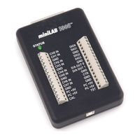
Measurement Computing miniLAB 1008 User Manual (78 pages)
USB Device for Analog and Digital I/O
Brand:
Measurement Computing
| Category:
Control Unit
| Size: 2.58 MB
Table of Contents
Table of Contents
5
About this User's Guide
9
Conventions in this User's Guide
9
Preface
9
What You will Learn from this User's Guide
9
Documents on MCC's Web Site
10
Documents on Your Local Drive
10
Where to Find more Information
10
Introducing the Minilab 1008
11
Minilab 1008 Block Diagram
12
Software Features
12
Instacal
13
Tracerdaq
13
Softwire Graphical Programming Limited Time License
14
Universal Library
14
Softwire MCC DAQ Components for .NET
15
Softwire MCC DAQ Controls for VB6
16
Universal Library for Labview
16
Connecting a Minilab 1008 to Your Computer Is Easy
17
Hardware
19
Installing the Minilab 1008
19
What Comes with Your Minilab 1008 Shipment
19
Documentation (PDF Format)
20
Software
20
Be Sure You Are Using the Latest System Software
21
Unpacking the Minilab 1008
21
Microsoft Data Access Components (MDAC)
22
NET Framework
22
USB Driver
22
Installing the Minilab 1008
23
Installing the Software
23
Installing Instacal, Tracerdaq, and the Universal Library
24
Installing Universal Library for Labview
25
Installing Softwire Graphical Programming
26
Installing Softwire MCC DAQ Components or Controls
26
Adding the Minilab 1008 to the Instacal Configuration File
27
Setting up the Minilab 1008 with Instacal
27
Configuring the Minilab 1008 with Instacal
29
Getting Started with Tracerdaq
31
Launching Tracerdaq from Instacal
31
Configuring Channel 0
33
Selecting the Channels to Use for Data
33
Configuring Channel 3
34
Setting up a Data Log File
36
Plotting and Logging Data on the Tracerdaq Strip Chart
37
Chapter 4 Functional Details
41
Theory of Operation - Analog Input Acquisition Modes
41
Software Paced Mode
41
Continuous Scan Mode
41
Burst Scan Mode
41
External Components
42
USB Connector
43
Status LED
43
Digital I/O Connector and Pin out
43
Screw Terminal Wiring
44
Main Connector and Pin out
46
Analog Input Terminals (CH0 in - CH7 In)
47
Digital I/O Terminals (DIO0 - DIO3)
50
Power Terminals
51
Ground Terminals
52
Calibration Terminal
52
Testing Terminal
52
Counter Terminal
52
Accuracy
52
Channel Gain Queue
55
Digital Connector Cabling
56
Calibrating and Testing the Device
59
Calibrating with Instacal
59
Testing with Instacal
62
Testing the Digital Functions
62
Testing the Analog Functions
64
Specifications
69
Analog Input Section
69
Analog Output Section
71
Digital Input / Output (Screw Terminal DIO3:0)
71
Digital Input / Output (DB37)
72
External Trigger
72
Counter Section
72
Non-Volatile Memory
73
Power
73
General
73
Environmental
73
Mechanical
74
Main Connector and Pin out
74
4-Channel Differential Mode
75
8-Channel Single-Ended Mode
75
DB37 Connector and Pin out
75
Advertisement
Measurement Computing miniLAB 1008 User Manual (34 pages)
USB-based Analog and Digital I/O Module
Brand:
Measurement Computing
| Category:
I/O Systems
| Size: 2.13 MB
Table of Contents
Table of Contents
5
About this User's Guide
7
What You will Learn from this User's Guide
7
Conventions in this User's Guide
7
Where to Find more Information
7
Preface
7
Chapter 1 Introducing the Minilab 100
8
Minilab 1008 Block Diagram
9
Software Features
9
Connecting a Minilab 1008 to Your Computer Is Easy
10
Chapter 2 Installing the Minilab 1008
11
What Comes with Your Minilab 1008 Shipment
11
Hardware
11
Additional Documentation
11
Unpacking the Minilab 1008
11
Installing the Software
12
Installing the Hardware
12
Chapter 3 Functional Details
13
Theory of Operation - Analog Input Acquisition Modes
13
Software Paced Mode
13
Continuous Scan Mode
13
Burst Scan Mode
13
External Components
14
USB Connector
14
Status LED
14
Digital I/O Connector and Pin out
15
Screw Terminal Wiring
16
Main Connectors and Pin Outs
17
Analog Input Terminals (CH0 in - CH7 In)
17
Digital I/O Terminals (DIO0 - DIO3)
20
Power Terminals
20
Ground Terminals
21
Calibration Terminal
21
Testing Terminal
21
Counter Terminal
21
Accuracy
22
Channel Gain Queue
24
Digital Connector Cabling
25
Chapter 4 Specifications
27
Analog Input
27
Analog Output
28
Digital Input / Output (Screw Terminal DIO3:0)
29
Digital Input / Output (DB37)
29
External Trigger
29
Counters
30
Non-Volatile Memory
30
Power
30
General
30
Environmental
30
Mechanical
31
Main Connector and Pin out
31
4-Channel Differential Mode
31
8-Channel Single-Ended Mode
31
DB37 Connector and Pin out
32
Advertisement
Related Products
Measurement Computing 140
Measurement Computing 101
Measurement Computing 121
Measurement Computing 142
Measurement Computing CIO-DAS16/M1/16
Measurement Computing CIO-DIO96
Measurement Computing E-DIO24
Measurement Computing E-DIO24-OEM
Measurement Computing PC-CARD-D24/CTR3
Measurement Computing PC-CARD-DAC08
Measurement Computing Categories
I/O Systems
Computer Hardware
Measuring Instruments
Data Loggers
PCI Card
More Measurement Computing Manuals
Login
Sign In
OR
Sign in with Facebook
Sign in with Google
Upload manual
Upload from disk
Upload from URL