Table of Contents
Advertisement
Quick Links
Advertisement
Table of Contents

Related Manuals for Measurement Computing miniLAB 1008


Summary of Contents for Measurement Computing miniLAB 1008
- Page 2 ™ miniLAB 1008 USB-based Analog and Digital I/O Module User's Guide Document Revision 8, May, 2006 © Copyright 2006, Measurement Computing Corporation...
- Page 3 Measurement Computing. Thank you for choosing a Measurement Computing product—and congratulations! You own the finest, and you can now enjoy the protection of the most comprehensive warranties and unmatched phone tech support. It’s the embodiment of our two missions: To offer the highest-quality, computer-based data acquisition, control, and GPIB hardware and software available—at...
- Page 4 Information furnished by Measurement Computing Corporation is believed to be accurate and reliable. However, no responsibility is assumed by Measurement Computing Corporation neither for its use; nor for any infringements of patents or other rights of third parties, which may result from its use. No license is granted by implication or otherwise under any patent or copyrights of Measurement Computing Corporation.
-
Page 5: Table Of Contents
Introducing the miniLAB 1008 ......................1-1 miniLAB 1008 block diagram ........................1-2 Software features ............................1-2 Connecting a miniLAB 1008 to your computer is easy.................. 1-3 Chapter 2 Installing the miniLAB 1008 ......................2-1 What comes with your miniLAB 1008 shipment? ..................2-1 Hardware .................................. - Page 6 1008 User's Guide Power................................4-4 General ................................4-4 Environmental ..............................4-4 Mechanical ..............................4-5 Main connector and pin out ..........................4-5 4-channel differential mode ............................4-5 8-channel single-ended mode............................4-5 DB37 connector and pin out ........................... 4-6...
-
Page 7: Preface
About this User's Guide What you will learn from this user's guide This user's guide explains how to install, configure, and use the miniLAB 1008. This guide also refers you to related documents available on our web site, and to technical support resources. -
Page 8: Introducing The Minilab 1008
Chapter 1 Introducing the miniLAB 1008 This user's guide contains all of the information you need to connect the miniLAB 1008 to your computer and to the signals you want to measure. The miniLAB 1008 is a USB 1.1 low-speed analog and digital I/O device that is supported under popular ®... -
Page 9: Minilab 1008 Block Diagram
Figure 1-2. miniLAB 1008 Functional Block Diagram Software features For information on the features of InstaCal and the other software included with your miniLAB 1008, refer to the Quick Start Guide that shipped with your device. The Quick Start Guide is also available in PDF at www.mccdaq.com/PDFmanuals/DAQ-Software-Quick-Start.pdf. -
Page 10: Connecting A Minilab 1008 To Your Computer Is Easy
HID because it is a standard, and its performance delivers full control and maximizes data transfer rates for your miniLAB 1008. No third-party device driver is required. The miniLAB 1008 is plug-and-play. There are no jumpers to position, DIP switches to set, or interrupts to configure. -
Page 11: Installing The Minilab 1008
As with any electronic device, you should take care while handling to avoid damage from static electricity. Before removing the miniLAB 1008 from its packaging, ground yourself using a wrist strap or by simply touching the computer chassis or other grounded object to eliminate any stored static charge. -
Page 12: Installing The Software
To connect the miniLAB 1008 to your system, turn your computer on, and connect the USB cable to a USB port on your computer or to an external USB hub that is connected to your computer. The USB cable provides power and communication to the miniLAB 1008. -
Page 13: Functional Details
Burst scan mode In burst scan mode, the miniLAB 1008 gathers data using the full capacity of its 4 K sample FIFO buffer. You can initiate a single acquisition sequence of one, two, or four channels by either a software command or an external hardware trigger. -
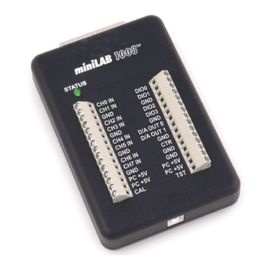
Page 14: External Components
Figure 3-1. miniLAB 1008 external components USB connector The USB connector is located on the bottom edge of the miniLAB 1008. This connector provides +5 V power and communication. The voltage supplied through the USB connector is system-dependent, and may be less than 5 V. -
Page 15: Digital I/O Connector And Pin Out
Port B0-B7 Port C0-C7 47 kilohm (kΩ) pull-up resistor and is configured as an input by default. If needed, the miniLAB 1008 can be factory configured to provide pull-down resistors. Caution! Port A0 through Port C7 have no overvoltage/short circuit protection. Do not exceed the voltage limits or you may damage the pin or the miniLAB 1008. -
Page 16: Screw Terminal Wiring
. The pins are labeled for eight-channel single-ended mode operations. Figure 3-3. miniLAB 1008 screw terminals Screw terminal pins 1-15 The screw terminals on the left edge of the miniLAB 1008 (pins 1 to 15) provide the following connections: Eight analog input connections ( CH0 IN... -
Page 17: Main Connectors And Pin Outs
Connector type 16 AWG to 26 AWG Wire gauge range 4-channel differential mode pin out Note that the pins are labeled for 8-channel single-ended mode on the miniLAB 1008. CH0 IN HI DIO0 CH0 IN LO DIO1 CH1 IN HI... - Page 18 1008 User's Guide Functional Details Single-ended configuration When all of the analog input channels are configured for single-ended input mode, eight analog channels are available. In single-ended mode, the input signal is referenced to signal ground (GND). The input signal is delivered through two wires: The wire carrying the signal to be measured connects to CH# IN.
- Page 19 1008 User's Guide Functional Details The input [common-mode voltage + signal] of the differential channel must be in the −10 V to +20 V range in order to yield a useful result. For example, you input a 4 volt peak-to-peak (Vpp) sine wave to CHHI, and apply the same sine wave 180° out of phase to CHLO.
-
Page 20: Digital I/O Terminals (Dio0 - Dio3)
The maximum total output current that can be drawn from all miniLAB 1008 connections (power, analog and digital outputs) is 500 mA. This maximum applies to most personal computers and self-powered USB hubs. -
Page 21: Ground Terminals
1008 device's USB +5 V as follows: (miniLAB 1008 @ 20 mA) + (4 DIO @ 2.5 mA ea) + (2 AO @ 30 mA ea ) = 90 mA For an application running on a PC or powered hub, this value yields a maximum user current of 500 mA − 90 mA = 410 mA. -
Page 22: Accuracy
The primary error sources in the miniLAB 1008 are offset and gain. Nonlinearity is small in the miniLAB 1008, and is not significant as an error source with respect to offset and gain. Figure 3-9 shows an ideal, error-free, miniLAB 1008 transfer function. The typical calibrated accuracy of the miniLAB 1008 is range-dependent, as explained in the "Specifications"... - Page 23 Figure 3-11. ADC Transfer function with gain error For example, the miniLAB 1008 exhibits a typical calibrated gain error of ±0.2% on all ranges. For the ±10 V range, this would yield 10V × ±0.002 = ±20 mV. This means that at full scale, neglecting the effect of offset for the moment, the measurement would be within 20 mV of the actual value.
-
Page 24: Channel Gain Queue
The channel gain queue feature removes the restriction of using an ascending channel sequence at a fixed gain. This feature creates a channel list which is written to local memory on the miniLAB 1008. This list is made up of a channel number and range setting. An example of a four-element list is shown in Ta ble 3-4 Table 3-4. -
Page 25: Digital Connector Cabling
1008 User's Guide Functional Details Digital connector cabling Table 3-5 lists the digital I/O connector, applicable cables and accessory equipment. The x in the compatible cable name indicates the length in feet of the cable. Table 3-5. Digital connector and accessory equipment... - Page 26 1008 User's Guide Functional Details The red stripe identifies pin # 1 Female connector Male connector Figure 3-15. C37FM-x cable 3-14...
-
Page 27: Specifications
Chapter 4 Specifications Typical for 25 °C unless otherwise specified. Specifications in italic text are guaranteed by design. Analog Input Parameter Conditions Specification A/D converter type Successive approximation type Input voltage range for linear operation, CHx to GND ±10 V max single-ended mode Input voltage range for linear operation, CHx to GND... -
Page 28: Analog Output
1008 User's Guide Specifications Table 6. Accuracy, differential mode Range Accuracy (LSB) ±20 V ±10 V ±5 V ±4 V ±2.5 V 12.1 ±2 V 14.1 ±1.25 V 20.1 ±1 V 24.1 Table 7. Accuracy, single-ended mode Range Accuracy (LSB) ±10 V... -
Page 29: Digital Input / Output (Screw Terminal Dio3:0)
1008 User's Guide Specifications Digital input / output (screw terminal DIO3:0) Parameter Conditions Specification Digital type Discrete, 5V/TTL compatible Number of I/O Configuration 4 bits, independently programmable for input or output. Input high voltage 3.0 V min, 15.0 V absolute max Input low voltage 0.8 V max... -
Page 30: Counters
1008 User's Guide Specifications Counters Counter type Event counter Number of channels Input source CTR screw terminal Input type TTL, rising edge triggered Resolution 32 bits Schmidt trigger hysteresis 20 mV to 100 mV Input leakage current ±1 µA... -
Page 31: Mechanical
1008 User's Guide Specifications Mechanical Case dimensions 157 mm (L) x 102 mm (W) x40 mm (H) , including connectors USB cable length 3 meters max User connection length 3 meters max Main connector and pin out Connector type... -
Page 32: Db37 Connector And Pin Out
1008 User's Guide Specifications DB37 connector and pin out Connector type 37 D-Type, shielded Compatible Cables C37FF-x C37FFS-x C37FM-x Compatible accessory products CIO-MINI37 SSR-RACK24 SSR-RACK08 CIO-ERB24 CIO-ERB08 Signal Name Signal Name USB +5V Out Port B7 Port C7 Port B6... - Page 33 Address: 10 Commerce Way Suite 1008 Norton, MA 02766 Measurement Computing Corporation declares under sole responsibility that the product miniLAB 1008 to which this declaration relates is in conformity with the relevant provisions of the following standards or other documents:...
- Page 34 Measurement Computing Corporation 10 Commerce Way Suite 1008 Norton, Massachusetts 02766 (508) 946-5100 Fax: (508) 946-9500 E-mail: info@mccdaq.com www.mccdaq.com...
Need help?
Do you have a question about the miniLAB 1008 and is the answer not in the manual?
Questions and answers