
Related Manuals for WAGO 750-481/003-000


Summary of Contents for WAGO 750-481/003-000
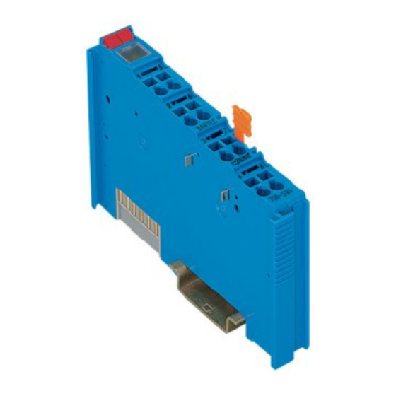
- Page 1 Fieldbus Independent I/O Modules 2 AI RTD EEx i 750-481/003-000 Manual Version 1.0.3...
- Page 2 • General Copyright 2007 by WAGO Kontakttechnik GmbH & Co. KG All rights reserved. WAGO Kontakttechnik GmbH & Co. KG Hansastraße 27 D-32423 Minden Phone: +49 (0) 571/8 87 – 0 Fax: +49 (0) 571/8 87 – 1 69 E-Mail: info@wago.com...
-
Page 3: Table Of Contents
Symbols ....................5 Number Notation..................5 Safety Notes ..................... 6 Scope ......................6 2 I/O Modules ....................7 Analog Input Modules................7 2.1.1 750-481/003-000 [2 AI RTD EEx i]............ 7 2.1.1.1 View....................7 2.1.1.2 Description..................7 2.1.1.3 Display Elements ................9 2.1.1.4... -
Page 4: Important Comments
WAGO Kontakttechnik GmbH & Co. KG declines all liability resulting from improper action and damage to WAGO products and third party products due to non-observance of the information contained in this manual. -
Page 5: Symbols
Routines or advice for efficient use of the device and software optimization. More information References on additional literature, manuals, data sheets and INTERNET pages 1.3 Number Notation Number Code Example Note Decimal normal notation Hexadecimal 0x64 C notation Binary '100' Within ', '0110.0100' Nibble separated with dots WAGO-I/O-SYSTEM 750 I/O Modules... -
Page 6: Safety Notes
Do not use any contact spray. The spray may impair the functioning of the contact area. The WAGO-I/O-SYSTEM 750 and its components are an open system. It must only be assembled in housings, cabinets or in electrical operation rooms. Access must only be given via a key or tool to authorized qualified personnel. -
Page 7: O Modules
Zones 0 and 1. It allows the connection of Pt and Ni resistance sensors potentiometers. The installation of the WAGO-I/O-SYSTEM 750 is to be done in Zone 2 or in non- hazardous environments. - Page 8 8 • 750-481/003-000 [2 AI RTD EEx i] Description The module has two input channels allowing the direct connection of two 2- or 3-wire resistance sensors. For example, two 3-wire sensors can be connected either to +R1, RL1 and –...
-
Page 9: Display Elements
However, if such a case should occur, another supply module must be added. The analog input module 750-481/003-000 can be used with all couplers/controllers of the WAGO-I/O-SYSTEM 750 (except for the economy types 750-320, -323, -324 and -327). -
Page 10: Schematic Diagram
24 V 24 V Error Function 10nF RL 1 / RL 2 330pF 330pF 4,7nF 330pF Shield - R 1 / - R 2 Shield (screen) (screen) 750-481/ 003-000 Fig. 2.1.1-3: 2-Channel Analog Input Module 750-481/003-000 g048101e WAGO-I/O-SYSTEM 750 I/O Modules... -
Page 11: Technical Data
750-481/003-000 [2 AI RTD EEx i] • 11 Technical Data 2.1.1.5 Technical Data Module Specific Data Number of inputs Voltage via power jumper contacts DC 24.7 V Supply via 750-625 Supply Module EEx i Current consumption (internal) 25 mA typ. - Page 12 100.0 mH 100.0 mH More Information Detailed references to the approvals are listed in the document "Overview Approvals WAGO-I/O-SYSTEM 750", which you can find on the CD ROM ELECTRONICC Tools and Docs (Item-No.: 0888-0412) or in the internet under: www.wago.com...
-
Page 13: Process Image
Some fieldbus systems can process input channel status information by means of a status byte. This status byte can be displayed via the starting tool WAGO-I/O-CHECK 2. However, processing via the coupler / controller is optional, which means that accessing or parsing the status information depends on the fieldbus system. -
Page 14: Configuration For Ni Resistance Sensors
14 • 750-481/003-000 [2 AI RTD EEx i] Process Image Configuration for Pt 100, Pt 200, Pt 500 and Pt 1000 Status- Temperature Numerical value byte Error °C binary hex. dec. hex. AI 1, 2 <-200.0 '1000.0000.0000.0001' 0x8001 -32767 0x41 -200.0... - Page 15 750-481/003-000 [2 AI RTD EEx i] • 15 Process Image Configuration for Ni 100 and Ni 1000 Status- Temperature Numerical value byte Error °C binary hex. dec. hex. AI 1,2 <-60.0 '1000.0000.0000.0001' 0x8001 -32767 0x41 -60.0 '1111.1101.1010.1000' 0xFDA8 -600 0x00 -50.0...
-
Page 16: Configuration For Resistance Measuring
16 • 750-481/003-000 [2 AI RTD EEx i] Process Image 2.1.1.6.3 Configuration for Resistance Measuring Resistance measuring Resistance measuring, Measuring range: 10 Ω ... 1.2 kΩ Resistance measuring, Measuring range: 10 Ω ... 5.0 kΩ Resistance measuring is only possible using 2-wire devices. -
Page 17: Configuration For Potentiometer Measuring
750-481/003-000 [2 AI RTD EEx i] • 17 Process Image 2.1.1.6.4 Configuration for Potentiometer Measuring Potentiometer measuring Total resistance 1.2 kΩ, Output of measured value in percent Total resistance 5.0 kΩ, Output of measured value in percent Potentiometer measuring is only possible using 3-wire devices. -
Page 18: Configuration With Wago-I/O-Check 2
Configuration with WAGO-I/O-CHECK 2 2.1.1.7 Configuration with WAGO-I/O-CHECK 2 The operating mode of the 750-481/003-000 module can be parameterized using the WAGO-I/O-CHECK 2 start-up and diagnostic tool (Item No.: 759- 302). The default setting is Pt 100. The parameter dialog box of WAGO-I/O-CHECK 2 contains select boxes that are used to set this module. - Page 19 750-481/003-000 [2 AI RTD EEx i] • 19 Configuration with WAGO-I/O-CHECK 2 In WAGO-I/O-CHECK 2, the following input boxes allow you to set the offset and gain values of the user and manufacturer scaling. Input box Offset Gain User Scaling...
-
Page 20: Use In Hazardous Environments
This is backed by law, directives or regulations on a national and international scale. WAGO-I/O-SYSTEM 750 (electrical components) is designed for use in zone 2 explosive environments. The following basic explosion protection related terms have been defined. -
Page 21: Explosion Protection Group
• IIA – Propane • IIB – Ethylene • IIC – Hydrogen Minimal ignition energy of representative types of gases Explosion group Gases Methane Propane Ethylene Hydrogen Ignition energy (µJ) WAGO-I/O-SYSTEM 750 I/O Modules... -
Page 22: Unit Categories
> 300 °C to 450 °C 200 °C > 200 °C to 300 °C 135 °C > 135 °C to 200 °C 100 °C >100 °C to 135 °C 85°C > 85 °C to 100 °C WAGO-I/O-SYSTEM 750 I/O Modules... -
Page 23: Types Of Ignition Protection
The standard EN 50 021 allows electrical component manufacturers to obtain certificates from the corresponding authorities for instance KEMA in the Netherlands or the PTB in Germany, certifying that the tested components meet the above mentioned standards draft. WAGO-I/O-SYSTEM 750 I/O Modules... -
Page 24: Classifications Meeting The Nec 500
Class I (gases and fumes): Group A (Acetylene) Group B (Hydrogen) Group C (Ethylene) Group D (Methane) Class II (dust): Group E (Metal dust) Group F (Coal dust) Group G (Flour, starch and cereal dust) Class III (fibers): No sub-groups WAGO-I/O-SYSTEM 750 I/O Modules... -
Page 25: Temperature Classes
160 °C >160 °C to 165 °C 135 °C >135 °C to 160 °C 120 °C >120 °C to 135 °C 100 °C >100 °C to 120 °C 85 °C > 85 °C to 100 °C WAGO-I/O-SYSTEM 750 I/O Modules... -
Page 26: Identification
Hansastr. 27 D-32423 Minden 0.08-2.5mm PATENTS PENDING II 3 G KEMA 01ATEX1024 X EEx nA II T4 Fig. 3.5.1-1: Example for lateral labeling of bus modules (750-400, 2 channel digital input module 24 V DC) g01xx03e WAGO-I/O-SYSTEM 750 I/O Modules... -
Page 27: For America
Hansastr. 27 D-32423 Minden 0.08-2.5mm PATENTS PENDING II 3 G KEMA 01ATEX1024 X EEx nA II T4 Fig. 3.5.2-1: Example for lateral labeling of bus modules (750-400, 2 channel digital input module 24 V DC) g01xx04e WAGO-I/O-SYSTEM 750 I/O Modules... -
Page 28: Installation Regulations
DIN VDE 0185 lightning protection systems The USA and Canada have their own regulations. The following are excerpts from these regulations: NFPA 70 National Electrical Code Art. 500 Hazardous Locations ANSI/ISA-RP Recommended Practice 12.6-1987 C22.1 Canadian Electrical Code WAGO-I/O-SYSTEM 750 I/O Modules... - Page 29 • 29 Installation regulations Danger When using the WAGO-I/O SYSTEM 750 (electrical operation) with Ex approval, the following points are mandatory: A. The fieldbus independent I/O System Modules Type 750-xxx are to be installed in enclosures that provide for the degree of ingress protection of at least IP54.
- Page 30 WAGO Kontakttechnik GmbH & Co. KG Postfach 2880 • D-32385 Minden Hansastraße 27 • D-32423 Minden Phone: 05 71/8 87 – 0 Fax: 05 71/8 87 – 1 69 E-Mail: info@wago.com Internet: http://www.wago.com...
Need help?
Do you have a question about the 750-481/003-000 and is the answer not in the manual?
Questions and answers