Table of Contents
Advertisement
Quick Links
Advertisement
Chapters
Table of Contents

Related Manuals for oventrop Regumaq X-45


Summary of Contents for oventrop Regumaq X-45
- Page 1 Regumaq X-45 Operating instructions...
-
Page 3: Table Of Contents
Regumaq X-45 Contents Page General information ......................7 Validity of the instructions ........................7 Type plate ............................... 7 Scope of delivery ............................ 7 Contact ..............................7 Declaration of conformity ........................7 Symbols used ............................7 Safety-related information ....................8 Intended use ............................8 Modifications to the product ........................ - Page 4 Regumaq X-45 Contents Page Mounting .......................... 23 Notes on mounting ..........................23 Wall mounting of the station ........................ 23 6.2.1 Required tools ............................23 6.2.2 Mounting ..............................24 Piping ..............................25 Protective equipotential bonding/earthing ................... 27 Commissioning .........................28 Filling and venting of the storage cylinder circuit .................. 28 Filling and venting of the potable water circuit ..................
- Page 5 Regumaq X-45 Contents Page 8.9.2 Storage cylinder loading ..........................43 8.9.3 Error relay ..............................43 8.9.4 Parallel relay ............................... 43 8.9.5 Function block (1 or 2) ..........................43 8.9.6 Thermal disinfection ........................... 43 8.10 Basic settings ............................44 8.11 MicroSD card slot ..........................44 8.11.1...
- Page 6 Regumaq X-45 Contents Page 14.2 Characteristic line for hot potable water preparation ................61 14.2.1 Heating of potable water from 10 °C to 45 °C .....................61 14.2.2 Heating of potable water from 10 °C to 50 °C .................... 62 14.2.3 Heating of potable water from 10 °C to 55 °C .................... 63 14.2.4 Heating of potable water from 10 °C to 60 °C ....................
-
Page 7: General Information
German. Action required • Validity of the instructions List These instructions are valid for the Regumaq X-45 fresh Fixed order. Steps 1 to X. water station. Type plate Result of action The type plate is attached to the bottom left of the upper shell from the outside. -
Page 8: Safety-Related Information
Regumaq X-45 Safety-related information 2. Safety-related information Warnings Each warning contains the following elements: Intended use Warning symbol SIGNAL WORD Operational safety is only guaranteed if the product is Type and source of danger used as intended. Possible consequences if the danger occurs or the The station is an electronically controlled product warning is ignored. -
Page 9: Safety Instructions
Regumaq X-45 Safety-related information Safety instructions 2.4.4 Risk of scalding due to hot water Due to setting or defect of the controller, the hot water We have developed this product in accordance with temperature at the draw-off points can rise up to the current safety requirements. -
Page 10: Damage To Property Due To Unsuitable Location
Regumaq X-45 Safety-related information 2.4.10 Damage to property due to unsuitable location Do not install the product in rooms prone to frost. Do not install the product in wet or damp environments. Do not install the product in rooms with corrosion- enhancing ambient air. -
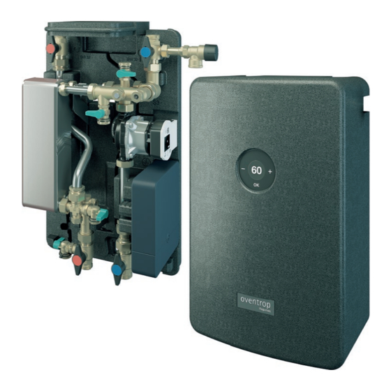
Page 11: Technical Description
Regumaq X-45 Technical description 3. Technical description Design Fig. 1: Regumaq X-45 138114082-V04.04.2022... - Page 12 Regumaq X-45 Technical description Temperature sensor for potable water (hot) S2 Temperature sensor for storage cylinder circuit S1 Heat exchanger Fill and drain ball valve for potable water (cold) Volume flow sensor for potable water circuit VTY 20 Fill and drain ball valve for storage cylinder circuit return...
-
Page 13: Functional Description
Based on the actual values for the volume fl ow and the temperature (of the potable water) recorded by the sensors, the controller calculates the pump speed Installation schemes Installation scheme with a Regumaq X-45 fresh water station Fig. 2: 138114082-V04.04.2022... -
Page 14: Fig. 3: Installation Scheme With Two Regumaq X-45 Fresh Water Stations
Potable water (hot) (PWH) Direction of fl ow If you operate several Regumaq X-45 stations in parallel, pipe the stations according to the Tichelmann's pipe routing in order to realise an even fl ow through the stations with the lowest possible resistance. -
Page 15: Application Example
VDI 2035/Ö-Norm (Austrian standard) Discharge capacity 1-45 l/min H5195-1, fluid category ≤ (at Δ T = 15K) 3 according to DIN EN 1717, (see Oventrop in- k v value 2.55 m3/h formation sheet on corro- sion protection in the Safety valve 10 bar... - Page 16 Regumaq X-45 Technical description Material Controller Valves and fittings Brass / dezincification re- Inputs 8 sensors, 1 Sika volume sistant brass flow sensor Seals Fibre material, EPDM Outputs 4 electromechanical re- lays, 1 potential-free relay Thermal insulation Expanded polypropylene and 4 PWM outputs Pipes Stainless steel 1.4404...
-
Page 17: Front View
Regumaq X-45 Technical description 3.5.1 Front view Fig. 4: Dimensions of the Regumaq X-45 in mm (front) 138114082-V04.04.2022... -
Page 18: Side View
Regumaq X-45 Technical description 3.5.2 Side view Fig. 5: Dimensions of the Regumaq X-45 in mm (side) 138114082-V04.04.2022... -
Page 19: Wall Bracket
Regumaq X-45 Technical description 3.5.3 Wall bracket Fig. 6: Dimensions of the Regumaq X-45 in mm (wall bracket) 138114082-V04.04.2022... -
Page 20: Terminal Assignment Of The Controller
Regumaq X-45 Technical description Terminal assignment of the controller – 240 V | 50 – 60 Hz T4A R1-4 | 1 (1) A 240 V~ Paul-Oventrop-Straße 1 X-45 IP 22 R5 | 4 (2) A (100 ... 240) V~ D-59939 Olsberg VN: 1.0... -
Page 21: Accessories And Spare Parts
1 ampere, it may be damaged. In this case, the Oventrop installation relay must be interposed. www.oventrop.com/qr/1381140 CAUTION Risk of injury due to incorrect accessories and... -
Page 22: Strainer
Regumaq X-45 Transport and storage 5. Transport and storage Strainer Temperature range 0 °C to +40 °C Relative air humidity Max. 95 % Particles Store in a dry and dust-protected place Mechanical infl u- Protected from mechanical ences shock Weather infl uences Do not store outdoors... -
Page 23: Mounting
Regumaq X-45 Mounting 6. Mounting NOTICE Damage to property due to overpressure in the DANGER system! The safety valve only protects the potable water Danger to life due to electric current! circuit within the fresh water station. There is a danger to life if live components are touched. -
Page 24: Mounting
Regumaq X-45 Mounting 6.2.2 Mounting use it as a drilling template. Mark two holes. To ensure that the magnetic contact is closed cor- rectly, the upper shell must be fi tted accurately. Avoid tilting. When mounting on a stud frame, make sure that in... -
Page 25: Piping
Regumaq X-45 Mounting Piping All four supply and return connections are sized G 1 (fl at sealing external thread). Fig. 16: Functional description Hot potable water return Cold potable water supply Storage cylinder circuit return Storage cylinder circuit supply Recess for the discharge elbow of the water sampling valve... -
Page 26: Fig. 17: Connection Of The Storage Cylinder Circuit Supply To The Buffer Storage Cylinder
We recommend the installation of a strainer in the storage cylinder circuit supply. • If necessary, mount another potable water fi lter (TF) (Oventrop accessory) as close as possible to the cold water connection of the station. • If a circulation pipe is used, install a strainer... -
Page 27: Protective Equipotential Bonding/Earthing
Regumaq X-45 Mounting Protective equipotential bonding/ earthing Protective equipotential bonding establishes a connection with good electrical conductivity be- tween conductive bodies of electrical equipment and the main equipotential bonding bar (main earthing bar) of the building. (According to DIN VDE 0100, bodies are touchable conductive parts which, in contrast to the “active parts”... -
Page 28: Commissioning
Regumaq X-45 Commissioning Commissioning NOTICE Risk of damage to due pressure surge! Filling and venting of the storage The abrupt fi lling of the station can lead to damage, cylinder circuit e.g. to the sensors or sealing points. Always open and close ball valves slowly. -
Page 29: Filling And Venting Of The Potable Water Circuit
Regumaq X-45 Commissioning Filling and venting of the potable NOTICE water circuit Risk of damage to due pressure surge! The abrupt fi lling of the station can lead to damage, e.g. to the sensors or sealing points. Always open and close ball valves slowly. -
Page 30: Power Supply Through The Pre-Assembled Mains Connection Cable
Regumaq X-45 Commissioning 7.3.1 Power supply through the pre- Carefully pull the controller off the lower shell as shown in Fig. 22 on page 30. assembled mains connection cable NOTICE A fused earthed socket must be available at the Damage to the electrical lines and connections installation location. -
Page 31: Fig. 23: Mounting Position
Regumaq X-45 Commissioning Loosen the screw (position in Fig. 24 on page 31) and put it aside. Slide the connection panel cover (position in Fig. 24 on page 31) upwards until it audibly clicks into place. Fold down the supply line cover (position in Fig. -
Page 32: Handover To The Operator
Regumaq X-45 Commissioning Handover to the operator Once commissioning has been completed, fill in the handover report. You will find a corresponding form in the appendix. Sign the report and give a copy to the operator. Pass on these instructions and all applicable instructions (e.g. -
Page 33: Operation
Regumaq X-45 Operation 8. Operation Main menu To go from the start screen to the main menu, press You can operate the station via the touch control panel in the touch key “OK”. the upper shell. The “Status” menu appears. -
Page 34: User Authorisations
Regumaq X-45 Operation User authorisations Settings can be made at three different authorisation levels. When setting ranges are defined, the setting options adapt to the restricted setting ranges. Example: If you limit the hot water setting range to 50 °C to 60 °C, the hot water temperature can only be selected from this range. -
Page 35: Status
Regumaq X-45 Operation 8.3.2 Status Hot water Hot water heating Auto Hot water set temp. Hot water temp. Store flow temp. Flow rate DHW (l/min) Pump power (%) Back Circulation Storage cylinder loading Return stratification The status of these functions is displayed when the corresponding Error relay functions have been activated. -
Page 36: Circulation
Regumaq X-45 Operation 8.3.4 Circulation Parameters Demand Min. impulse duration 0 - Max. impulse duration Max. impulse duration Min. impulse duration - 15 s Runtime circulation 1 - 15 min pump (min) Wait. time (min) 1 - 15 min Sensor demand... -
Page 37: Additional Functions
Regumaq X-45 Operation 8.3.5 Additional functions Parameters Return strat- Deactivat- ification Activated Relay -, R1,R2, R3, R4, R5, PWM2, PWM3, PWM4 Store sensor -, S4, S5, S6, S7, S8 Sensor return temp. -, S3, S4, S5, S6, S7, S8 Relay inverted... - Page 38 Regumaq X-45 Operation Parameters Thermostat a Switch-on 10 - 100 °C (visible when activat- temperature Switch-off 10 - 100 °C temperature Sensor -, S1, S2, S3, S4, S5, S6, S7, S8 Back Thermostat b Deactivated, Activated Thermostat b Switch-on 10 - 100 °C...
-
Page 39: Basic Settings
Regumaq X-45 Operation 8.3.6 Basic settings Parameters Language EN, DE, FR, NL, IT, ES, RU, BG, RO Date Day, Month, Year Time Hour, Min. Summer/Winter time Yes, No Display standby 30 - 300 s Display mode White on black, Black on white... -
Page 40: Controller Presettings
Regumaq X-45 Operation Controller presettings Return stratification Relay 8.4.1 Circulation (presetting 1) Store sensor Mode Continuous operation Sensor return Relay temp. Connection PWM1 Storage cylinder loading pump Mode Fixed value 8.4.2 Storage cylinder loading (presetting 2) Relay Mode Fixed value... -
Page 41: Reset
Regumaq X-45 Operation frame. 8.6.2 Emergency operation To set a time frame for the previously saved weekdays, Emergency operation means that the pump is select “New time frame”. permanently switched on. Confi rm the set time frame with “Save”. If emergency operation has been activated, the... -
Page 42: Circulation
Regumaq X-45 Operation Circulation Additional functions If you use the circulation set, you can confi gure the 8.9.1 Return stratifi cation function in the controller menu. The return stratifi cation serves to protect the temperature Observe the operating instructions supplied with the stratifi cation in the storage cylinder from mixing while the circulation set. -
Page 43: Storage Cylinder Loading
Regumaq X-45 Operation 8.9.2 Storage cylinder loading 8.9.5.1 Thermostat function 2 modes are available for reheating (backup heating): When the set switch-on temperature is reached, the switching condition for the thermostat function is In fixed value mode, the flow setpoint temperature is considered fulfilled. -
Page 44: Basic Settings
Regumaq X-45 Operation 8.10 Basic settings NOTICE In the “Basic settings” menu, all basic parameters for the Damage to the electrical lines and connections station can be set. due to tensile forces! Electrical lines or connections can break if 8.11 MicroSD card slot excessive tensile forces are applied. -
Page 45: Updating The Firmware On The Controller
Regumaq X-45 Operation Loosen the screw (position in Fig. 31 on page 45) and put it aside. Slide the connection panel cover (position in Fig. 31 on page 45) upwards beyond the catches. Insert the microSD card into the card slot. -
Page 46: End Of Recording
Regumaq X-45 Operation 8.15 Replacement of the fuse 8.11.4 End of recording Select the menu item “Remove card” and remove the card. The controller is protected by a fuse (T4AH250V) (position in Fig. 16 on page 25). 8.11.5 Saving of the controller settings... -
Page 47: Troubleshooting
Regumaq X-45 Troubleshooting 9. Troubleshooting Troubleshooting table MALFUNCTION CAUSE REMEDY The display is permanently off. The controller is in standby mode. Press a key to activate the display. The power supply to the controller is Establish the power supply. interrupted. -
Page 48: Nominal Resistances Of The Temperature Sensors
This can be the result of a heat exchanger to the potable water quality heat exchanger that is unsuitable for (see Oventrop information sheet on corro- Pressure increase in the storage the potable water quality. sion protection in the appendix). -
Page 49: Decalcification Of The Heat Exchanger
Regumaq X-45 Troubleshooting Decalcifi cation of the heat Close the shutoff ball valve for storage cylinder circuit supply (position in Fig. 1 on page 11). exchanger Unscrew the caps of the fi ll and drain ball valves for If you notice during operation of the system that the... -
Page 50: Cleaning Of The Heat Exchanger (Storage Cylinder Circuit Side)
Regumaq X-45 Troubleshooting 9.3.2 Cleaning of the heat exchanger (storage NOTICE cylinder circuit side) Risk of damage due to pressure surge! A loss of performance may also be due to contamination The abrupt injection of water into the station can of the storage cylinder circuit. -
Page 51: Decalcification Of The Removed Heat Exchanger
Regumaq X-45 Troubleshooting 9.3.3 Decalcifi cation of the removed heat exchanger CAUTION Risk of scalding due to hot media! If the station has been in operation, there is a risk of scalding due to unintentional escape of hot water or water steam. -
Page 52: Cleaning Of The Volume Flow Sensor
Regumaq X-45 Troubleshooting Cleaning of the volume fl ow sensor 9.4.1 Required tools • If not hot potable water can be added at the draw-off 24, 37 and 38 mm spanner points, there is an operational fault. As listed in the •... -
Page 53: Fig. 34: Cleaning Of The Measuring Turbine
Regumaq X-45 Troubleshooting in Fig. 34 on page 53). A water hose with an appropriate spray nozzle is particularly suitable for this purpose. Check that the measuring turbine has been cleared of foreign substances and is running smoothly again. If the cleaning was successful, install the fi tting in the reverse order of removal. -
Page 54: Fig. 36: Loosening Of The Measuring Turbine
Regumaq X-45 Troubleshooting Fig. 36: Loosening of the measuring turbine Fig. 38: Correct positioning of the measuring turbine Carefully push the sleeve with measuring turbine out with your fi nger in the direction of fl ow until it can be Guide the sleeve with measuring turbine back into the moved freely. -
Page 55: Maintenance
Regumaq X-45 Maintenance 10. Maintenance 10.1.3 Functional check of the safety valves (potable water circuit) CAUTION Check the function of the safety valves at six-month intervals in accordance with DIN EN 806-5. Risk of scalding due to hot media! If the station has been in operation, there is a risk of 10.1.4 Water sampling... -
Page 56: Replacement Of The Potable Water Filter Insert
Regumaq X-45 Notes for the operator 10.1.8 Replacement of the potable water fi lter CAUTION insert Risk of scalding due to excessively hot potable During maintenance, also consider the potable water fi lter water at the draw off points! installed in the cold water inlet of the station. -
Page 57: Dismantling And Disposal
Regumaq X-45 Dismantling and disposal 12. Dismantling and disposal 12.2 Disposal When the fresh water station reaches the end of its service NOTICE life or has an irreparable defect, it must be dismantled and Risk of environmental pollution! disposed of in an environmentally friendly manner or the Incorrect disposal (for instance with domestic components must be recycled. -
Page 58: List Of Figures
13. List of figures Fig. 1: Regumaq X-45 ..........................11 Fig. 2: Installation scheme with a Regumaq X-45 fresh water station ..........13 Fig. 3: Installation scheme with two Regumaq X-45 fresh water stations .........14 Fig. 4: Dimensions of the Regumaq X-45 in mm (front) ..............17 Fig. - Page 59 Regumaq X-45 List of figures Fig. 42: Storage cylinder circuit volume flow - heating of potable water to 45 °C ........ 61 Fig. 43: Storage cylinder circuit return temperature - heating of potable water to 45 °C..... 61 Fig. 44: Storage cylinder circuit volume flow - heating of potable water to 50 °C ........62...
-
Page 60: Appendix
Regumaq X-45 Appendix 14. Appendix 14.1 Characteristic line for Wilo circulation pump H / m ∆p / kPa Q / m³/h Fig. 39: Characteristic line for Wilo circulation pump (storage cylinder circuit) Pressure loss during hot potable water preparation - Storage cylinder circuit -... -
Page 61: Characteristic Line For Hot Potable Water Preparation
Regumaq X-45 Appendix 14.2 Characteristic line for hot potable water preparation 14.2.1 Heating of potable water from 10 °C to 45 °C Performance data according to SPF test procedure. Volume flow storage cylinder circuit at different flow temperatures - Heating of potable water from 10 °C to 45 °C - 2400 55°C... -
Page 62: Heating Of Potable Water From 10 °C To 50 °C
Regumaq X-45 Appendix 14.2.2 Heating of potable water from 10 °C to 50 °C Performance data according to SPF test procedure. Volume flow storage cylinder circuit at different flow temperatures - Heating of potable water from 10 °C to 50 °C - 2400 50°C... -
Page 63: Heating Of Potable Water From 10 °C To 55 °C
Regumaq X-45 Appendix 14.2.3 Heating of potable water from 10 °C to 55 °C Performance data according to SPF test procedure. Volume flow storage cylinder circuit at different flow temperatures - Heating of potable water from 10 °C to 55 °C - 2400 55°C... -
Page 64: Heating Of Potable Water From 10 °C To 60 °C
Regumaq X-45 Appendix 14.2.4 Heating of potable water from 10 °C to 60 °C Performance data according to SPF test procedure. Volume flow storage cylinder circuit at different flow temperatures - Heating of potable water from 10 °C to 60 °C - 2400 75°C... -
Page 65: Heating Of Potable Water From 10 °C To 65 °C
Regumaq X-45 Appendix 14.2.5 Heating of potable water from 10 °C to 65 °C Performance data according to SPF test procedure. Volume flow storage cylinder circuit at different flow temperatures - Heating of potable water from 10 °C to 65 °C - 2400 65°C... -
Page 66: Heating Of Potable Water From 10 °C To 70 °C
Regumaq X-45 Appendix 14.2.6 Heating of potable water from 10 °C to 70 °C Performance data according to SPF test procedure. Volume flow storage cylinder circuit at different flow temperatures - Heating of potable water from 10 °C to 70 °C - 2400 70°C... -
Page 67: Heating Of Potable Water From 10 °C To 75 °C
Regumaq X-45 Appendix 14.2.7 Heating of potable water from 10 °C to 75 °C Performance data according to SPF test procedure. Volume flow storage cylinder circuit at different flow temperatures - Heating of potable water from 10 °C to 75 °C - 2400 90°C... -
Page 68: Eu Declaration Of Conformity
Regumaq X-45 Appendix 14.3 EU Declaration of conformity 138114082-V04.04.2022... - Page 69 Fresh water station Regumaq X-45 Notes on corrosion protection The materials used in the Oventrop fresh water and The following table contains limit values of potable water dwelling stations are selected and processed in constituents when using heat exchangers with different accordance with strict quality specifications.
- Page 70 Special notes for corrosion protection NOTICE High media temperatures (>60 °C) increase the risk of corrosion Do not set the hot water temperature and the flow temperature of the heating water higher than necessary. NOTICE Long stagnation periods increase the risk of corrosion Flush the system manually or automatically on a regular basis if longer stagnation periods are to be expected all the time (VDI/DVGW 6023).
- Page 71 Fresh water station Regumaq X-45 Handover report Date: Installation location address / building Address operator Address installation company Regumaq X-45 serial number Give reasons for items that have not Tick as appropriate or en- Remarks / Settings ter value/number been carried out or for items that have...
- Page 72 Which setpoint temperature for the °C storage cylinder was set at the heat generator? ¨ ¨ Are all ball valves open? Give reasons for items that have not Tick as appropriate or en- Remarks / Settings ter value/number been carried out or for items that have been answered with No in the Remarks field! Controller settings...
- Page 73 Final inspection Has the installation been tested for ¨ ¨ leaks (DIN EN 806)? Has the functional check been car- ¨ ¨ ried out according to the operating instructions? Relay assignment Relay Function Sensors Instruction/Handover ¨ The installer has instructed the operator in the function and intended use of the fresh water station. ¨...
- Page 75 Fresh water station Regumaq X-45 Maintenance report Date: Installation location address / building Address operator Address installation company Regumaq X-45 serial number Give reasons for items that have not Tick as appropriate or en- Remarks / Settings ter value/number been carried out or for items that have...
- Page 76 Has the heat exchanger been ¨ ¨ checked for external leaks? Has a functional test been carried out to verify performance (see oper- ¨ ¨ ating instructions for functional con- trol)? Have all ball valves been checked for ¨ ¨ free movement? Have any strainers installed on site ¨...
- Page 77 ¨ ¨ Is an error displayed? Have any other modifications been ¨ ¨ made to the settings of the control- ler? Give reasons for items that have not Tick as appropriate or en- Remarks / Settings ter value/number been carried out or for items that have been answered with No in the Remarks field! Repair work (only fill in in case of repair or replacement of components)
- Page 78 Instruction/Handover ¨ The installer has informed the operator about the maintenance work carried out. ¨ The installer has informed the operator about possible modifications and repair work. ¨ The installer has handed over the necessary documents to the operator. Information on the intended operation of potable water installations: - Stagnation must be avoided, regular potable water exchange must be ensured - TPWH >= 60 °C must be maintained at the hot water outlet - The circulation system must be designed in such a way that the potable water temperature does not fall below the station...
- Page 80 Oventrop GmbH & Co. KG · Paul-Oventrop-Str. 1 · 59939 Olsberg Tel. +49 2962 820 · Fax +49 2962 82400 · mail@oventrop.com · www.oventrop.com...
Need help?
Do you have a question about the Regumaq X-45 and is the answer not in the manual?
Questions and answers