
Summary of Contents for Technosoft IPS110
- Page 1 IPS110 Version 1.0 Intelligent Stepper Minidrive for Step and Intelligent Stepper Minidrive Brushed DC Motors Technical Reference © Technosoft 2007...
- Page 3 TECHNOSOFT IPS110 v1.0 Technical Reference P091.045.IPS110.UM.1007 Technosoft S.A. Buchaux 38 CH-2022 Bevaix, NE Switzerland Tel.: +41 (0) 32 732 5500 Fax: +41 (0) 32 732 5504 contact@technosoftmotion.com www.technosoftmotion.com...
- Page 5 Whilst Technosoft believes that the information and guidance given in this manual is correct, all parties must rely upon their own skill and judgment when making use of it. Technosoft does not assume any liability to anyone for any loss or damage caused by any error or omission in the work, whether such error or omission is the result of negligence or any other cause.
- Page 7 This manual covers Step 1 in detail. It describes the IPS110 hardware including the technical data, the connectors and the wiring diagrams needed for installation. The manual also presents an overview of the following steps, and includes the scaling factors between the real SI units and the drive internal units.
- Page 8 TML_LIB_LabVIEW v2.0 (part no. P091.040.LABVIEW.v20.UM.xxxx) – explains how to program in LabVIEW a motion application for the Technosoft intelligent drives using TML_LIB_Labview v2.0 motion control library for PCs. The TML_Lib_LabVIEW includes over 40 ready-to-run examples. TML_LIB_S7 (part no. P091.040.S7.UM.xxxx) – explains how to program in a PLC Siemens series S7-300 or S7-400 a motion application for the Technosoft intelligent drives using TML_LIB_S7 motion control library.
-
Page 9: Table Of Contents
Product Overview..................3 2.1. Introduction..................... 3 2.2. Key Features ..................4 2.3. Supported Motor-Sensor Configurations ..........5 2.4. IPS110 Dimensions ................7 2.5. Electrical Specifications................8 Step 1. Hardware Installation ..............13 3.1. Mounting....................13 3.2. Connectors and Connection Diagrams..........13 3.2.1. - Page 10 Executing TML programs ................54 5.3.3. Loading Automatically Cam Tables Defined in EasyMotion Studio ..... 54 5.3.4. Customizing the Homing Procedures (for IPS110 CAN executions) ... 55 5.3.5. Customizing the Drive Reaction to Fault Conditions (for IPS110 CAN executions)........................ 55 5.4.
- Page 11 DC brushed motor with quadrature encoder on motor ......66 6.12.2. Stepper motor open-loop control. No feedback device or incremental encoder on load ......................67 6.12.3. Stepper motor closed-loop control. Incremental encoder on motor..67 Memory Map .....................68 © Technosoft 2007 IPS110 Technical Reference...
- Page 12 © Technosoft 2007 IPS110 Technical Reference...
-
Page 13: Safety Information
ELECTRICAL SHOCKS. DO NOT TOUCH LIVE PARTS WHILE THE POWER SUPPLIES ARE ON TO AVOID ELECTRIC ARCING AND HAZARDS, NEVER WARNING! CONNECT / DISCONNECT WIRES FROM THE DRIVE WHILE THE POWER SUPPLIES ARE ON © Technosoft 2007 IPS110 Technical Reference... -
Page 14: Cautions
THE POWER SUPPLIES CONNECTED TO THE DRIVE CAUTION! MUST COMPLY WITH THE PARAMETERS SPECIFIED IN THIS DOCUMENT TROUBLESHOOTING AND SERVICING ARE PERMITTED CAUTION! ONLY FOR PERSONNEL AUTHORISED BY TECHNOSOFT THE DRIVE CONTAINS ELECTROSTATICALLY SENSITIVE COMPONENTS WHICH DAMAGED CAUTION! INCORRECT HANDLING. THEREFORE THE DRIVE SHALL... -
Page 15: Product Overview
2. Product Overview 2.1. Introduction The IPS110 is a family of intelligent stepper minidrive, based on the latest DSP technology and they offer unprecedented drive performance combined with an embedded motion controller. Suitable for control of brushed DC and step motors, the IPS110 drives accept as position feedback incremental encoders (quadrature). -
Page 16: Key Features
Apart from a CANopen master, the IPS110 drives can also be controlled from a PC or PLC using the family of TML_LIB motion libraries. For all motion programming options, the IPS110 commissioning for your application is done using EasySetUp. 2.2. Key Features •... -
Page 17: Supported Motor-Sensor Configurations
IU units, refer to the motor. IPS110 Figure 2.2. No position or speed feedback. Open-loop control: motor position or speed . For higher ambient temperatures see the de-rating information below © Technosoft 2007 IPS110 Technical Reference... - Page 18 SI units (or derivatives) refer to the load , while the same commands, expressed in IU units refer to the motor. IPS110 Figure 2.4. Encoder on motor shaft. Closed-loop control: motor position, speed or torque © Technosoft 2007 IPS110 Technical Reference...
-
Page 19: Ips110 Dimensions
2.4. IPS110 Dimensions The next figure presents the IPS110 drives dimensions. Figure 2.5. IPS110 drives dimensions © Technosoft 2007 IPS110 Technical Reference... -
Page 20: Electrical Specifications
Normal operation Motor Supply Input Measured between +V and GND. Min. Typ. Max. Units Operating voltages, including ripple & braking-induced over-voltage Absolute maximum values, continuous Supply voltage IPS110 Absolute maximum values, surge -0.5 † (duration ≤ 10mS) DC-bus capacitor connected... - Page 21 ESD Protection Human Body Model (100 pF, 1.5 KΩ) Encoder Inputs Min. Typ. Max. Units Standards compliance Differential / RS422 Low level input current Internal 1 kΩ pull-ups to +5 V Input frequency Input hysteresis © Technosoft 2007 IPS110 Technical Reference...
- Page 22 Recommended transmission line Ω Measured at 1MHz impedance Bit rate Depending on software settings 125K Baud Number of network nodes Depending on software settings ±15 ESD Protection Human Body Model (100 pF, 1.5 KΩ) © Technosoft 2007 IPS110 Technical Reference...
- Page 23 Figure 2.6. De-rating with ambient temperature At altitudes over 1,000m, current and power rating are reduced due to thermal dissipation efficiency at higher altitudes. See Figure 2.7 - De-rating with altitude – the nominal current Stand-alone operation, vertical mounting © Technosoft 2007 IPS110 Technical Reference...
- Page 24 PWM frequency with the motor parameters in order to avoid possible motor damage. Figure 2.10. Power De-rating with PWM Figure 2.11. Over-current diagram frequency – the output voltage, V – the motor supply voltage – the nominal power © Technosoft 2007 IPS110 Technical Reference...
-
Page 25: Step 1. Hardware Installation
3. Step 1. Hardware Installation 3.1. Mounting The IPS110 drive was designed to be cooled by natural convection. It shall be mounted horizontally on a printed circuit board. Figure 3.1. Recommended mounting of IPS110 on a printed circuit board 3.2. Connectors and Connection Diagrams 3.2.1. -
Page 26: Identification Labels
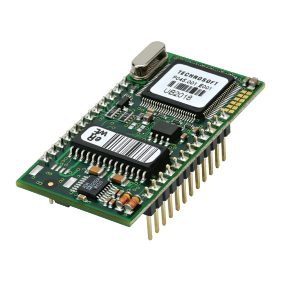
Figure 3.2. IPS110 connectors layout 3.2.2. Identification Labels © Technosoft 2007 IPS110 Technical Reference... - Page 27 T E C H N O S O F T Drive Name IPS110 Article Number Serial Number AB1234 P045.001.E001 Figure 3.3. IPS110, RS232 Identification Label Manufacturer T E C H N O S O F T Drive Name IPS110 Article Number Serial Number AB1234 P045.001.E002...
-
Page 28: J1 Connector Pinout
Motor- for DC brush motors Ground Ground Positive terminal of the logic supply: 5 V TX232 RS-232 Data Transmission RX232 RS-232 Data Reception RESET signal – connect to GND to reset the RESET board © Technosoft 2007 IPS110 Technical Reference... -
Page 29: J2 Connector Pinout
(from a tachometer). CAN_H CAN-Bus positive line (positive during dominant bit). Not connected on the no-CAN execution of the IPS110 drive (P045.001.E001) CAN_L CAN-Bus negative line (negative during dominant bit) Not connected on the no-CAN execution of the IPS110 drive (P045.001.E001) -
Page 30: Supply Connection
3.2.5.1 Recommendations for Supply Wiring 1. Use short, thick wires between the IPS110 and the motor power supply. If the wires are longer than 2 meters, use twisted wires for the supply and ground return. For wires longer than 20 meters, add a capacitor of at least 1,000 μF (rated at an appropriate voltage) right on the terminals of the IPS110. - Page 31 – final system altitude [m] final – motor current during deceleration [A /phase] – motor phase resistance [Ω] – time to decelerate [s] – total friction torque as seen at motor shaft [Nm] – includes load and transmission © Technosoft 2007 IPS110 Technical Reference...
-
Page 32: Motor Connections
10 000 μF / 100V. 3.2.6. Motor connections IPS110 Step motor connection 1 coil per phase MotionChip 2 coils per phase 2 coils per phase in parallel in series connection connection Figure 3.7. J1 – Step motor connection © Technosoft 2007 IPS110 Technical Reference... - Page 33 (hundreds of meters) are used, this condition may not be met. In this case, add series inductors between the IPS110 outputs and the cable. The inductors must be magnetically shielded (toroidal, for example), and must be rated for the motor surge current. Typically the necessary values are around 100 μH.
-
Page 34: Feedback Connections
3.2.7. Feedback connections Encoder Connection IPS110v1.0 3 x 4K7 ENCA ENCB ENCZ Figure 3.9. Single-ended / open-collector encoder connection © Technosoft 2007 IPS110 Technical Reference... - Page 35 Master Shield ENCA ENCB Analog Inputs IPS110 v1.0 +3.3V +3.3V Slave 100K 100K 470R FEEDBACK 470R REFERENCE 100K 100K Slave +3.3V Encoder Motor phases Figure 3.10. Master - Slave connection using second encoder input © Technosoft 2007 IPS110 Technical Reference...
-
Page 36: Digital I/O Connections
Always use shielded cables to avoid capacitive-coupled noise when using cable lengths over 1 meter. Connect the cable shield to the earth potential, at only one end. This point could be either the IPS110 (using the GND pin) or the encoder / motor. Do not connect the shield at both ends. - Page 37 PROGRAM THE IO#35 AND IO#36 AS OUTPUT PINS IN ORDER TO AVOID POSSIBLE DRIVE DAMAGE. CONNECTOR SIGNALS ELECTRO- CAUTION! STATICALLY SENSITIVE . THE IPS110 SHALL BE HANDLED ONLY IN AN ESD PROTECTED ENVIRONMENT. 3.2.8.2 Pulse & Direction Inputs connection Pulse & Direction IPS110 v1.0...
- Page 38 3. Use one twisted pair for each differential group of signals as follows: Puls+ with Puls- and Dir+ with Dir-. Also connect the GND between the IPS110 and the P&D generator. WHEN USING THE IO#35, IO#36 AS INPUTS, DO NOT...
-
Page 39: Analog Inputs Connection
If the signal source output voltage is out of the range 0-3.3V, use a 2-resistor differential divider, located near the IPS110 I/O connector. Choose the divider resistances as low as possible, close to the signal source output current limit, to minimize the noise ©... -
Page 40: Serial Rs-232 Communication Connections
Transceiver Figure 3.15. Serial RS-232 connection 3.2.10.1 Recommendations for RS-232 Wiring a) Always power-off all the IPS110 supplies before inserting/removing the RS-232 serial connector. b) Use a 9-wire standard 1-to-1 (non-inverting) shielded cable, preferable with metallic or metallized shells (casings) -
Page 41: Can Communication Connection
These resistors are not included on the drive. 2. Both CAN signals are NOT insulated from all other IPS110 circuits . CAN signals (CAN_H and CAN_L pins of J2 connector) are not connected pins on the IPS110 drive execution P045.001.E001. - Page 42 AXISID = 2 IPS110 AXISID = 3 IPS110 AXISID = 127/255 Figure 3.17. Multiple-Axis CAN network The maximum value of the AXISID is 127 for the IPS110 CANopen execution and 255 for IPS110 CAN executions © Technosoft 2007 IPS110 Technical Reference...
-
Page 43: Connectors Type And Mating Connectors
FISCHER Precision female FISCHER Standard header ELEKTRONIK socket ELEKTRONIK square pin J1, J2 BL 5 12 SL 1 053 012 G 2.54 mm pitch 0.635 x 0.635 mm; 2.54 mm pitch © Technosoft 2007 IPS110 Technical Reference... -
Page 44: Jumper And Solder Joints Configuration
IPS110 in Autorun (stand-alone) mode. After reset, automatically executes a program from the internal E ROM. • OPEN: IPS110 in External (slave) mode. After reset, waits for commands from an external device. JP2: FU / Norm • SHORT: Enable firmware update •... - Page 45 OPEN OPEN SHORT OPEN SHORT OPEN OPEN OPEN SHORT SHORT SHORT OPEN OPEN SHORT OPEN OPEN SHORT OPEN OPEN SHORT OPEN SHORT SHORT OPEN OPEN SHORT SHORT OPEN SHORT OPEN OPEN SHORT SHORT SHORT © Technosoft 2007 IPS110 Technical Reference...
- Page 46 SHORT OPEN Technosoft drives can be set with axis ID values from 1 to 255. In CANopen protocol the maximum axis number is 127. When CANopen protocol is used, the CAN communication sees the drives axis ID modulo 128. The correspondence is given in Table 3.1. In order to avoid having multiple devices with the same Axis ID, do not use in the same CANopen network drives having the same Axis ID in modulo 128.
- Page 47 ID areas not covered by CANopen. TechnoCAN protocol offers the possibility to inspect the status of ALL Technosoft drives connected on a CANopen network. This operation is done using EasySetUp or EasyMotion Studio and a single RS-232 link with any of the drives from the CANopen network.
-
Page 48: First Power-Up
Power supply connections and their voltage levels Motor connections Serial cable connections Axis-ID solder joints configuration EasySetUp is installed on the PC which is serially connected with the drive (see chapter Step 2. Drive Setup © Technosoft 2007 IPS110 Technical Reference... -
Page 49: Step 2. Drive Setup
4. Step 2. Drive Setup 4.1. Installing EasySetUp EasySetUp is a PC software platform for the setup of the Technosoft drives. It can be downloaded free of charge from Technosoft web page. EasySetUp comes with an Update via Internet tool through which you can check if your software version is up-to-date, and when necessary download and install the latest updates. -
Page 50: Establish Communication
• Implement on your master the TML commands you need to send to the drives/motors using one of the supported communication channels. The implementation must be done according with Technosoft communication protocols. • Combine TML programming at drive level with one of the other options (see Section 5.3) 4.2.1. -
Page 51: Setup Drive/Motor
Communication | Setup dialogue at “Axis ID of drive/motor connected to PC” the option Autodetected. 4.2.2. Setup drive/motor Press New button and select your drive type. The selection continues with the motor technology (for example: 2 phase closed loop) and type of feedback device (Incremental encoder). © Technosoft 2007 IPS110 Technical Reference... - Page 52 The selection opens 2 setup dialogues: for Motor Setup and for Drive setup through which you can configure and parameterize a Technosoft drive, plus several predefined control panels customized for the product selected. In the Motor setup dialogue you can introduce the data of your motor and the associated sensors.
-
Page 53: Download Setup Data To Drive/Motor
Status control panel to find the cause. 4.3. Changing the drive Axis ID The axis ID of an IPS110 drive can be set in 2 ways: Hardware (H/W) – according with the solder joints configuration in the range 1 to 31 or 255 (see 3.3 Jumper and solder joint configuration) -
Page 54: Setting Canbus Rate
Communication | Scan Network 4.4. Setting CANbus rate The IPS110 drives can work with the following rates on the CAN: 125kHz, 250kHz, 500KHz, 1MHz. In the Drive Setup dialogue you can choose the initial CAN rate after power on. This information is stored in the setup table. -
Page 55: Creating An Image File With The Setup Data
The .sw file can be programmed into a drive: from a CANopen master, using the communication objects for writing data into the drive EEPROM from a host PC or PLC, using the TML_LIB functions for writing data into the drive EEPROM © Technosoft 2007 IPS110 Technical Reference... -
Page 56: Step 3. Motion Programming
Transmit PDOs are used to send data from the drive, and receive PDOs are used to receive on to the drive. The IPS110 accepts 4 transmit PDOs and 4 receive PDOs. The contents of the PDOs can be set according with the application needs using the dynamic PDO-mapping. -
Page 57: Technocan Extension (For Ips110 Can Executions)
5.1.2. TechnoCAN Extension (for IPS110 CAN executions) In order to take full advantage of the powerful Technosoft Motion Language (TML) built into the IPS110, Technosoft has developed an extension to CANopen, called TechnoCAN through which TML commands can be exchanged with the drives. -
Page 58: Using The Built-In Motion Controller And Tml
.sw file (see 4.5 and 5.2.4 for details) whether the non-volatile EEPROM memory of an IPS110 drive contains the right information. If the checksum reported by the drive doesn’t match with that computed from the .sw file, the CANopen master can download the entire .sw file into the drive EEPROM using the communication objects for writing data into the drive EEPROM. -
Page 59: Installing Easymotion Studio
EasyMotion Studio is an integrated development environment for the setup and motion programming of Technosoft intelligent drives. It comes with an Update via Internet tool through which you can check if your software version is up-to-date, and when necessary download and install the latest updates. - Page 60 The motion component contains the motion sequences to do. These are described via a TML (Technosoft Motion Language) program, which is executed by the drives/motors built-in motion controller. 5.2.3.1 Create a new project EasyMotion Studio starts with an empty window from where you can create a new project or open a previously created one.
- Page 61 Click on your selection. EasyMotion Studio opens the Project window where on the left side you can see the structure of a project. At beginning both the new project and its first application are named “Untitled”. The application has 2 components: S Setup and M Motion (program). © Technosoft 2007 IPS110 Technical Reference...
- Page 62 ID=255 (default communication settings). If your drive is powered with all the DIP switches OFF and it is connected to your PC port COM1 via an RS-232 cable, the communication shall establish automatically. © Technosoft 2007 IPS110 Technical Reference...
- Page 63 Setup and for Drive Setup (same like on EasySetUp) through which you can configure and parameterize a Technosoft drive. In the Motor setup dialogue you can introduce the data of your motor and the associated sensors. Data introduction is accompanied by a series of tests having as goal to check the connections to the drive and/or to determine or validate a part of the motor and sensors parameters.
- Page 64 PC upload setup data from a drive/motor EEPROM memory 5.2.3.4 Program motion In the project window left side, select “M Motion”, for motion programming. This automatically activates the Motion Wizard. © Technosoft 2007 IPS110 Technical Reference...
-
Page 65: Creating An Image File With The Setup Data And The Tml Program
EEPROM of your drive. This includes both the setup data and the motion The customization of the interrupt service routines and homing routines is available only for IPS110 CAN executions Optional for IPS110 CANopen execution ©... -
Page 66: Combining Canopen /Or Other Host With Tml
EasyMotion Studio as TML programming tool Remark: If you don’t use the advanced features presented below you don’t need EasyMotion Studio. In this case the IPS110 is treated like a standard CANopen drive, whose setup is done using EasySetUp. -
Page 67: Customizing The Homing Procedures (For Ips110 Can Executions)
5.3.4. Customizing the Homing Procedures (for IPS110 CAN executions) The IPS110 supports all homing modes defined in DSP-402 device profile. If needed, any of these homing modes can be customized. In order to do this you need to select the Homing Modes from your EasyMotion Studio application and in the right side to set as “User defined”... -
Page 68: Using Motion Libraries For Pc-Based Systems
A TML Library for PC is a collection of high-level functions allowing you to control from a PC a network of Technosoft intelligent drives. It is an ideal tool for quick implementation on PCs of motion control applications with Technosoft products. -
Page 69: Scaling Factors
6. Scaling Factors Technosoft drives work with parameters and variables represented in the drive internal units (IU). These correspond to various signal types: position, speed, current, voltage, etc. Each type of signal has its own internal representation in IU and a specific scaling factor. This chapter presents the drive internal units and their relation with the international standard units (SI). -
Page 70: Stepper Motor Closed-Loop Control. Incremental Encoder On Motor
No_encoder_lines – is the encoder number of lines per revolution SI units for position are [rad] for a rotary movement , [m] for a linear movement SI units for speed are [rad/s] for a rotary movement, [m/s] for a linear movement © Technosoft 2007 IPS110 Technical Reference... -
Page 71: Stepper Motor Open-Loop Control. No Feedback Device
SI units × π × Load Speed Motor Speed × × × encoder lines SI units for speed are [rad/s] for a rotary movement , [m/s] for a linear movement © Technosoft 2007 IPS110 Technical Reference... -
Page 72: Acceleration Units
SI units SI units for acceleration are [rad/s ] for a rotary movement, [m/s ] for a linear movement SI units for acceleration are [rad/s ] for rotary movement, [m/s ] for linear movement © Technosoft 2007 IPS110 Technical Reference... -
Page 73: Stepper Motor Open-Loop Control. Incremental Encoder On Load
T – is the slow loop sampling period expressed in [s]. You can read this value in the “Advanced” dialogue, which can be opened from the “Drive Setup” SI units for acceleration are [rad/s ] for rotary movement, [m/s ] for linear movement © Technosoft 2007 IPS110 Technical Reference... -
Page 74: Jerk Units
T – is the slow loop sampling period expressed in [s]. You can read this value in the “Advanced” dialogue, which can be opened from the “Drive Setup” SI units for jerk are [rad/s ] for a rotary movement, [m/s ] for a linear movement © Technosoft 2007 IPS110 Technical Reference... -
Page 75: Stepper Motor Open-Loop Control. Incremental Encoder On Load
The internal voltage command units refer to the voltages applied on the motor. The significance of the voltage commands as well as the scaling factors, depend on the motor type and control method used. © Technosoft 2007 IPS110 Technical Reference... -
Page 76: Voltage Measurement Units
When the master position is sent via a communication channel or via pulse & direction signals, the master position units depend on the type of position sensor present on the master axis. When the master position is an encoder the correspondence with the international standard (SI) units is: © Technosoft 2007 IPS110 Technical Reference... -
Page 77: Master Speed Units
The internal motor position units are motor µsteps. The correspondence with the motor position in SI units is: SI units for motor position are: [rad] for a rotary motor, [m] for a linear motor © Technosoft 2007 IPS110 Technical Reference... -
Page 78: Stepper Motor Open-Loop Control. Incremental Encoder On Load
Encoder_accuracy – is the linear encoder accuracy i.e. distance in [m] between 2 pulses T – is the slow loop sampling period expressed in [s]. You can read this value in the “Advanced” dialogue, which can be opened from the “Drive Setup” © Technosoft 2007 IPS110 Technical Reference... -
Page 79: Stepper Motor Open-Loop Control. No Feedback Device Or Incremental Encoder On Load
T – is the slow loop sampling period expressed in [s]. You can read this value in the “Advanced” dialogue, which can be opened from the “Drive Setup”. SI units for motor speed are [rad/s] for a rotary motor, [m/s] for a linear motor © Technosoft 2007 IPS110 Technical Reference... -
Page 80: Memory Map
0FFFh 87FFh Figure 7.1. IPS110 Memory Map The SRAM memory is mapped both in the program space (from 8270h to 87FFh) and in the data space (from A70h to FFFh). The data memory can be used for real-time data acquisition and to temporarily save variables during a TML program execution. - Page 81 Remark: EasyMotion Studio handles automatically the memory allocation for each motion application. The memory map can be accessed and modified from the main folder of each application © Technosoft 2007 IPS110 Technical Reference...
- Page 82 This page is empty © Technosoft 2007 IPS110 Technical Reference...
Need help?
Do you have a question about the IPS110 and is the answer not in the manual?
Questions and answers