Table of Contents
Advertisement
READ AND SAVE THESE INSTRUCTIONS
FUSION
USER
MANUAL
PN 20-86531
Fusion Model GMSV4H, GMSV6H and GMSV8H
and GMSV8H.7215 Mid-Volume, Angled Back,
Vertical Glass, Heated Service Merchandisers
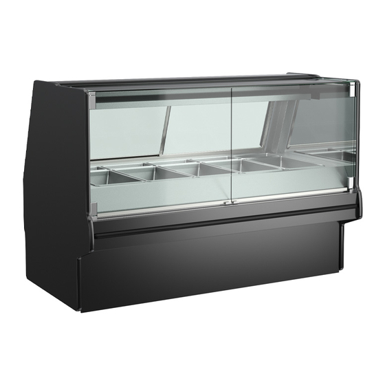
Model GMSV4H
Model GMSV6H
Model GMSV8H
Structural Concepts Corp. ∙ 888 E. Porter Rd ∙ Muskegon, MI 49441 Phone: 231.798.8888 Fax: 231.798.4960 ∙ www.structuralconcepts.com
USER MANUALS\20-86531_FUSION_HTD_SVC_VERT GLASS CASE_USER MANUAL_GMSV(L)H
Rev D Date: 07/13/2022
Advertisement
Table of Contents

Subscribe to Our Youtube Channel
Related Manuals for Structural Concepts FUSION GMSV6H


Summary of Contents for Structural Concepts FUSION GMSV6H
- Page 1 GMSV8H.7215 Mid-Volume, Angled Back, Vertical Glass, Heated Service Merchandisers Model GMSV4H Model GMSV6H Model GMSV8H Structural Concepts Corp. ∙ 888 E. Porter Rd ∙ Muskegon, MI 49441 Phone: 231.798.8888 Fax: 231.798.4960 ∙ www.structuralconcepts.com USER MANUALS\20-86531_FUSION_HTD_SVC_VERT GLASS CASE_USER MANUAL_GMSV(L)H Rev D Date: 07/13/2022...
-
Page 2: Table Of Contents
TABLE OF CONTENTS OVERVIEW / CONDITION TYPE / TEMP / COMPLIANCE / WARNINGS / PRECAUTIONS / WIRING ……………………………………………………………..…………………………………. INSTALLATION INSTRUCTIONS ...………………..………………………………...…...…………………. INSTALLATION INSTRUCTIONS, CONT’D: SEALING AND BOLTING HEATED CASES TOGETHER …………………………………………………………………………………………….. START-UP / LIGHTING / CASE TEMP. / CAREL® iJF PROGRAMMABLE CONTROLLERS / OPERATION ..………………………………………………………………………………………….. - Page 3 INTEGRATED AVERAGE PRODUCT TEMPERATURE OVERVIEW This merchandiser is designed for dry heating operations The Structural Concepts® Fusion Service Deli throughout the product area. The heat is generated from Merchandisers are designed to merchandise product electric rod well warmers, overhead ceramic heaters and at an integrated average product temperature of overhead ceramic metal halide lamps.
-
Page 4: Wiring
OVERVIEW / TYPE / TEMP / COMPLIANCE / WARNINGS / PRECAUTIONS / WIRING - PAGE 2 of 2 PRECAUTIONS WIRING DIAGRAM Following are important precautions to prevent Each case has its own wiring diagram folded and in damage to unit or merchandise. its own packet. -
Page 5: Installation Instructions
INSTALLATION INSTRUCTIONS Installation Note: Units shown may not depict an exact representation of your particular unit being installed. 1. Remove Unit From Skid Caution: case must always remain supported or center of gravity will allow case to fall. Slide unit to rear of skid and tip backward off skid. -
Page 6: Installation Instructions, Cont'd: Sealing And Bolting Heated Cases Together
INSTALLATION INSTRUCTIONS, CONT’D: SEALING AND BOLTING HEATED CASES TOGETHER shown with floating arrowheads below ( ). You Sealing and Bolting Heated Cases Together may need to remove decking, side covers, ‘perf’ Follow these steps to assure a secure, level lineup. panel, etc. -
Page 7: Operation
START-UP / LIGHTING / CASE TEMP. / CAREL® iJF PROGRAMMABLE CONTROLLERS / OPERATION 1. Merchandiser Start-Up Caution: Case Temperature dial reflects internal case temperature ONLY (not product temperature). Case must be field wired. Use a food probe to determine ACTUAL product ... -
Page 8: Electrical Connections: Access And Field Wiring
ELECTRICAL CONNECTIONS: ACCESS AND FIELD WIRING 1. Electrical Connections: Access knockout). Access is now available to programmable controllers, terminal strip, ballasts, A. View of case rear. Power to case must be terminal block, LED, etc. turned off before accessing rear control panel. >... -
Page 9: Well Heat
WELL HEAT factory to heat wells at proper temperatures. Well Heat Modifications to these settings should be rare. Turn on main power switch. Should programmable controllers need to be Well heat is controlled by Carel® iJF revised, see CAREL® iJF PLATFORM Programmable Controllers. -
Page 10: Overhead Ceramic Heaters
OVERHEAD CERAMIC HEATERS See Carel® iJF Programmable Controller section Overhead Ceramic Heaters in this manual for specifics. When main power switch is turned on, overhead Warning! Disconnect power before providing ceramic heaters are energized. maintenance & service to unit. ... -
Page 11: Overhead Ceramic Metal Halide Light Fixtures
OVERHEAD CERAMIC METAL HALIDE LIGHT FIXTURES As ceramic metal halide lamps may take up to 15 Overhead Ceramic Metal Halide Light Fixtures minutes to gain full illumination, turn on lamps Warning! Lamps are NOT manufactured to BEFORE loading product into case. This will allow resist breakage. -
Page 12: Hinged Front Glass Doors
HINGED FRONT GLASS DOORS Hinged Front Glass Doors Doors are on side hinges. Simply grasp lower handle and pull outward. Gently return front glass doors to original position. See illustration below. Front Door Lower Door Front Handles Doors Front... -
Page 13: Rear Sliding Doors / Rear Ledge
REAR SLIDING DOORS / REAR LEDGE 1. Rear Sliding Doors 2. Rear Ledge Note: Rear sliding doors are not interchangeable. Rear Ledge is connected to shelf track. Illustrations There is an inner and outer door. The outer door must at right reflect step-by-step removal method (as be removed first and replaced last. -
Page 14: Optional Scale Stand
OPTIONAL SCALE STAND Optional Scale Stand Scale stand is provided with receptacle which is to be wired separately. Depending upon order, scale stand may be at either left or right of case. View of Typical Case With Scale Stand, Receptacle and CAT-5 Connector Note: Illustration Shown May Not Exactly Reflect Every Feature or... -
Page 15: Removing Pans And Dividers (For Cleaning)
REMOVING PANS AND DIVIDERS (FOR CLEANING) Removing Pans and Dividers (for Cleaning) 3. Perform cleaning service on pan warmer shield. 4. Replace pan dividers and pans in reverse order they Note: Make certain that unit has been turned off and were removed. -
Page 16: Cleaning Schedule
CLEANING SCHEDULE Warnings: 1. DO NOT clean heated wells while hot. Flip Well Heater Switches to OFF position. Allow wells to cool to room temperature before cleaning. 2. Lowering the front glass with items inside top cap can cause damage to case. 3. -
Page 17: Troubleshooting
TROUBLESHOOTING Trouble Possible Solution System is not operating Check that the utility power is on. Check that the MAIN Power Switch is on. Check the circuit breaker box for tripped circuits. Warmers will not heat Check that temperature controllers (at case rear) are at proper settings. -
Page 18: Serial Label Location & Info Listed / Tech Info & Service - Ambient/Heated Case
TECHNICAL SERVICE page in this manual for Serial labels are affixed at a wide range of places instructions on contacting Structural Concepts’ (on the header, at case rear, behind panels or Technical Service Department. toe-kicks, on electrical boxes, etc.). -
Page 19: Carel® Ijf Platform Programmable Controller For Heated Cases - Page 1 Of 4
See next page for programmable controller keypad. 2. Overview 4. Programmable Controller Limitations These Structural Concepts Reveal® heated cases are Case thermometer measures air temperature. designed to hold pre-heated, perishable, packaged It does NOT reflect actual shelf or product foods at 140 °F to 180 °F (60 °C to 82 °C). - Page 20 CAREL® iJF PLATFORM PROGRAMMABLE CONTROLLER FOR HEATED CASES - PAGE 2 of 4 7. Keypad Overview This data derived from tCAREL Programmable Controller Material +0300010EN - rel. 1.0 - 10.05.2021 ||| User Manual/Carel_iJF Platform_Prog-Cont for Htd Cases_User Manual_4-Pager ||| Rev A Date: 06/22/2022 >...
- Page 21 CAREL® iJF PLATFORM PROGRAMMABLE CONTROLLER FOR HEATED CASES - PAGE 3 of 4 8. Screen Navigation - User Settings The figures below show how to navigate between screens on the display for USER SETTINGS only. Establishing USER SETTINGS are the MOST COMMON reason for needing to navigate the screen. ...
- Page 22 The need to establish factory settings is seldom needed. If you must do so, it is suggested that you contact Structural Concepts technical support. HOWEVER, if you are not able to reach Structural Concepts, and must navigate the screen on your own, follow these steps.
-
Page 23: Technical Service Contact Information & Warranty Information
LIMITED WARRANTY Overview: All sales by Structural Concepts Corporation (hereafter, “SCC”) are subject to the following limited warranty. “Goods” refers to the product or products being sold by SCC. Warranty Scope: Warranty is for equipment sold in the United States, Canada, Mexico and Puerto Rico. Equipment sold elsewhere may carry modified warranties.
Need help?
Do you have a question about the FUSION GMSV6H and is the answer not in the manual?
Questions and answers