Table of Contents
Advertisement
Quick Links
Reveal
REVEAL® FREE STANDING SELF-SERVICE
REFRIGERATED MERCHANDISERS
> SELF-CONTAINED OR REMOTE UNITS
> CAUTION! DO NOT PUSH OR PULL ON END PANELS!
> ONLY USE HANDLES (ON CASE) TO PUSH OR PULL
CASE INTO POSITION!
> SINGLE ACCESS MODELS: REAR SLIDING DOORS
WITH PERFORATED PLENUMS OR SOLID BACK PANELS
> DUAL ACCESS MODELS: BACK-TO-BACK
PERFORATED PLENUMS
> SEE PAGES 10-11 FOR PANEL, GRILLE & TOE-KICK
ATTACHMENT INSTRUCTIONS
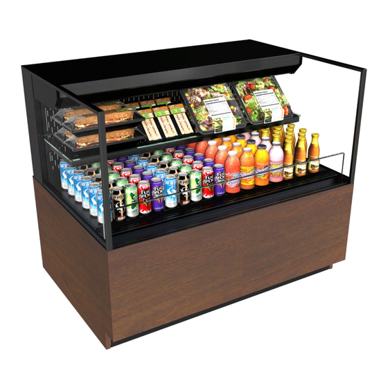
Model With Rear Sliding Doors and Acrylic
Perforated Plenums (Cladding Attached)
Perforated Rear Panel Model Shown (Cladding Attached)
Operating Manuals\Reveal_Free Standing Refrig Self-Service Cases 20-78252.pub
READ AND SAVE THESE INSTRUCTIONS
®
Structural Concepts Corporation ∙ 888 E. Porter Road ∙ Muskegon, MI 49441 Phone: 231.798.8888 Fax: 231.798.4960 ∙ www.structuralconcepts.com
INSTALLATION
& OPERATING
MANUAL
Models Are Shipped WITHOUT Panels and
Cladding Attached. See Pages 10 and 11
for Component Attachment Instructions.
Perforated Rear Panel Model Shown (Cladding
Removed For Illustrative Purposes Only)
Dual Access Model With Perforated Back-To-Back
Rear Panels (Cladding Remove For
Illustrative Purposes Only)
SCC P/N
20-78252
Rev J Date: 1.14.2020
Advertisement
Table of Contents
Troubleshooting

Related Manuals for Structural Concepts Reveal NR3633RSSV


Summary of Contents for Structural Concepts Reveal NR3633RSSV
- Page 1 Perforated Rear Panel Model Shown (Cladding Attached) Rear Panels (Cladding Remove For Illustrative Purposes Only) Structural Concepts Corporation ∙ 888 E. Porter Road ∙ Muskegon, MI 49441 Phone: 231.798.8888 Fax: 231.798.4960 ∙ www.structuralconcepts.com Rev J Date: 1.14.2020 Operating Manuals\Reveal_Free Standing Refrig Self-Service Cases 20-78252.pub...
-
Page 2: Table Of Contents
TABLE OF CONTENTS TABLE OF CONTENTS …………………………………………………………………………………...…... REVEAL® FREE STANDING REFRIGERATED SELF-SERVICE MODEL APPLICABILITY AND INDIVIDUAL MODEL DIMENSIONS ……………...………………………………………………... OVERVIEW / DISPLAY TYPE I vs. II / COMPLIANCE / WARNINGS / PRECAUTIONS ……………... INSTALLATION: TOE-KICK & AIR INTAKE GRILLE REMOVAL / DISCONNECTING CASE FROM PALLET ...…...…………………………………………………………………………………………. -
Page 3: Reveal® Free Standing Refrigerated Self-Service Model Applicability And Individual Model Dimensions
REVEAL® FREE STANDING REFRIGERATED SELF-SERVICE MODEL APPLICABILITY & DIMENSIONS Upper Display Model Overall Case Height Case Depth x Width Case Height NR3633RSSV 13 5/8” 32 7/8” 33”D* x 35 3/4”W NR3640RSSV 20 3/8” 39 5/8” 33”D* x 35 3/4”W NR3647RSSV 27 7/8”... -
Page 4: Overview / Display Type I Vs. Ii / Compliance / Warnings / Precautions - Page 1 Of 2
Type II display refrigerators are intended for use in an area where environmental conditions are controlled and These Structural Concepts Reveal® cases are maintained so that the ambient temperature does not designed to merchandise packaged products at exceed 80 °F (27 °C) and 55% maximum humidity. - Page 5 WIRING DIAGRAM This disclosure statement has been reviewed and approved by Structural Concepts and Structural Concepts attests, Each case has its own wiring diagram folded and in its under penalty of perjury, that these statements are true and own packet.
-
Page 6: Installation: Toe-Kick & Air Intake Grille Removal / Disconnecting Case From
INSTALLATION: TOE-KICK & AIR INTAKE GRILLE REMOVAL / DISCONNECTING CASE FROM PALLET 1. Cases With Rear Access Condenser Package Only: Remove Front Toe-Kick To prevent damage to case, remove front toe-kick from case before removing from pallet. Toe-kick is held in place by magnets only. No screw removal is required. -
Page 7: Installation, Cont'd.: Caster Adjustment / Lock / Unlock / Case Removal
INSTALLATION, CONT’D.: CASTER ADJUSTMENT / LOCK / UNLOCK / CASE REMOVAL FROM PALLET 4. Caster Height: Raising and Lowering Vertical Raise or lower casters (to adjust case height) by Adjustment rotating casters’ vertical adjustment rings. Ring Rotate vertical adjustment ring clockwise to lower caster (and increase height of case). -
Page 8: Installation, Cont'd: Shelving Assembly Components
INSTALLATION, CONT’D: SHELVING ASSEMBLY COMPONENTS 8. Shelving Assembly Components discard thumbscrews (using pliers, if necessary) after case is installed so shelves can be Check that glass shelving is in proper position disassembled (to clean or service). before placing product in case G. -
Page 9: Installation, Cont'd: Plug In Unit / Main Power Switch / Turn On Led Lights
INSTALLATION, CONT’D: PLUG IN UNIT / MAIN POWER SWITCH / TURN ON LED LIGHTS 9. Plug Case In / Turn Main Power Switch On Factory-Supplied Power Cord With Plug Power cord with plug is factory-supplied. Plug case into customer-supplied electrical outlet. ... -
Page 10: Installation, Cont'd: Shipping Brace / Attaching Front Panel Components
INSTALLATION, CONT’D: SHIPPING BRACE / ATTACHING FRONT PANEL COMPONENTS / HANDLES Then, slide front panel into case until it attaches 11. Remove Shipping Brace to case via lower magnets. Shipping brace keeps condenser package secure See illustration below. during shipment and while positioning case. -
Page 11: Installation, Cont'd: Attaching Side Panels, Rear Panel And Rear Grille
INSTALLATION, CONT’D: ATTACHING SIDE PANELS, REAR PANEL AND REAR GRILLE 16. Attaching Rear Grille 14. Attaching Side Panels Use finger holes to place rear grille’s inner hooks Attach side panels to case using slot/hook method. onto case rear’s lower shoulder screws. ... -
Page 12: Installation, Cont'd: Optional Acrylic Security Cover
INSTALLATION, CONT’D: OPTIONAL ACRYLIC SECURITY COVER D. Upper acrylic security cover must rest against upper 17. Optional Acrylic Security Cover security cover stop. Lock at both ends of cover with Note: Illustrations reflects random model; it may not locking mechanism. reflect every feature or option of your case. -
Page 13: Case Design: Front View Of Free Standing, Self-Service Merchandisers
CASE DESIGN: FRONT VIEW OF FREE STANDING, SELF-SERVICE MERCHANDISERS 1. Front View Of Free Standing, Self-Service Merchandisers Model illustrated below may not reflect every feature or option of your particular merchandiser. Solid back panel is shown. Your unit may have acrylic perforated plenums (controlled by rear door brackets’... -
Page 14: Case Design, Cont'd: Rear View Of Free Standing, Self-Service Merchandisers
CASE DESIGN, CONT’D: REAR VIEW OF FREE STANDING, SELF-SERVICE MERCHANDISERS 2. Rear View Of Free Standing, Self-Service Merchandisers Model illustrated below may not reflect every feature or option of your particular merchandiser. Solid back rear panel is shown. Rear sliding doors with acrylic perforated plenums may be on your model. ... -
Page 15: Case Design, Cont'd: Controller / Dc Drivers / Main Power Switch
CASE DESIGN, CONT’D: CONTROLLER / DC DRIVERS / MAIN POWER SWITCH / COIL FILTER 3. Controller / DC Driver Access / Components Remove 4 screws from the controller/DC driver box cover to access electrical Remove air intake grille with slot/hook method; components. -
Page 16: Case Design, Cont'd: Night Curtain Access And Operation
CASE DESIGN, CONT’D: NIGHT CURTAIN ACCESS AND OPERATION 4. Night Curtain Access and Operation Acrylic Air Air Return Deflector Grille The night curtain saves energy by preventing outside ambient air from entering case. Use night curtain whenever possible. A. Night curtain is attached to inside of case at underside of air return grille and decks (at case front). -
Page 17: Case Design, Cont'd: Tub Area (After Deck Pan Removal)
CASE DESIGN, CONT’D: TUB AREA (AFTER DECK PAN REMOVAL) 5. Tub Area After Deck Pan Removal Note: Refrigeration service to be accomplished by refrigeration / electrical contractors only. Caution! Turn main power off before accessing tub area. Illustration below shown after removal of deck pans. ... -
Page 18: Case Design, Cont'd: Led Light Switch Locations / Led Lights / Thermometer
CASE DESIGN, CONT’D: LED LIGHT SWITCH LOCATIONS / LED LIGHTS / THERMOMETER 8. Thermometer Function & Placement 6. LED Light Switch Locations Cases with lower rear sliding doors have Cases with rear sliding doors have light switch different thermometer location than units with solid in column cover (for easy access at case rear). -
Page 19: Case Design, Cont'd: Rear Sliding Door Removal / Rear Perforated Plenum
CASE DESIGN, CONT’D: REAR SLIDING DOOR REMOVAL / REAR PERFORATED PLENUM CONTROL 9. Rear Sliding Door Removal 10. Rear Perforated Plenum Control To remove rear sliding doors, move rear doors Optional acrylic perforated plenums are shown. toward center of the case. Your unit may have solid back panel. -
Page 20: Control
CASE DESIGN, CONT’D: CONDENSER PACKAGE (SELF-CONTAINED UNITS ONLY) 11. Condenser Package (Self-Contained Units Only) Assembly/disassembly and servicing to be performed by licensed refrigeration contractor. Condensate Package Configuration Illustration below may not reflect every feature or option of your particular condenser package. Optional Clean Sweep®... -
Page 21: Product Placement / Honeycomb Airflow Consideration / Load Lines
START-UP AND OPERATION, CONTINUED: LOAD LIMITS PRODUCT PLACEMENT / HONEYCOMB AIRFLOW CONSIDERATION / LOAD LINES 1. Product Placement 3. Load Lines Product can be placed on decking or steps Load lines limit where product can be placed (risers) within self-service display area. and/or stacked in case. -
Page 22: Cleaning Schedule (To Be Performed By Store Personnel)
CLEANING SCHEDULE (TO BE PERFORMED BY STORE PERSONNEL) FREQ. INSTRUCTIONS Daily Glass Surfaces: Clean side glass and shelves with household or commercial glass cleaner. Daily Rear Sliding Door Exterior Glass: Clean with household or commercial glass cleaner. Clean out rear door track with moist cloth. Daily End Panels, Front Panel, Toe-Kick, etc.: Wipe off all surfaces with warm water and mild soap solution and non-abrasive cloth. -
Page 23: Preventive Maintenance (To Be Performed By Trained Service Provider) - Page 1 Of 3
PREVENTIVE MAINTENANCE (TO BE PERFORMED BY TRAINED SERVICE PROVIDER) - PAGE 1 OF 3 WARNING! TURN OFF CASE BEFORE PERFORMING PREVENTIVE MAINTENANCE! FREQ. INSTRUCTIONS Quarterly Condensing Coil: Remove air intake grille to access area. Simply lift up and off. ... - Page 24 PREVENTIVE MAINTENANCE (TO BE PERFORMED BY TRAINED SERVICE PROVIDER) - PAGE 2 OF 3 NOTE: PREVENTIVE MAINTENANCE IS TO BE Honeycomb PERFORMED BY TRAINED SERVICE PROVIDERS Air Diffuser ONLY. Preventive maintenance should be performed quarterly (unless conditions warrant a more frequent replacement cycle).
- Page 25 PREVENTIVE MAINTENANCE (TO BE PERFORMED BY TRAINED SERVICE PROVIDER) - PAGE 3 OF 3 FREQUENCY INSTRUCTIONS Quarterly Optional Clean Sweep™ Condensing Coil Cleaner: Disconnect power from case before servicing the Clean Sweep™ Condenser Coil Cleaner! Remove air intake grille (by lifting up and off); no screw removal is required. ...
-
Page 26: Troubleshooting (To Be Performed By Store Personnel Only)
TROUBLESHOOTING (TO BE PERFORMED BY STORE PERSONNEL) - PAGE 1 OF 2 CONDITION TROUBLESHOOTING Water Is On The Floor Call service provider. Fan Emits Excessive Noise Call service provider. Case is Not Holding Proper If a large amount of warm product was added to the case, it will take time Temperature for the temperature to adjust. - Page 27 Troubleshooting to be performed by trained service providers only is on next page. If case light still do not come on, it may need to be replaced. Contact Structural Concepts’ Technical Service Department for replacement light (see TECHNICAL SERVICE section of this manual for contact information). ...
- Page 28 TROUBLESHOOTING (TO BE PERFORMED BY TRAINED SERVICE PROVIDERS ONLY) - PAGE 1 OF 4 CONDITION TROUBLESHOOTING Water Is On The Caution! Disruption of power or malfunctioning condensate pan (or electric coil Floor overflow condensate pan) may cause water to overflow pan and seep onto flooring causing damage! Until condensate pan(s) are functioning (or are replaced), follow these procedures: ...
- Page 29 TROUBLESHOOTING (TO BE PERFORMED BY TRAINED SERVICE PROVIDERS ONLY), PAGE 2 OF 4 CONDITION TROUBLESHOOTING Fans Emit Check that the case is aligned, level and plumb. Excessive Noise Check evaporator fans for cleanliness. Unplug/power off fan motors. Check motor shaft for bearing wear. Check that fan motors are securely mounted in brackets.
- Page 30 TROUBLESHOOTING (TO BE PERFORMED BY TRAINED SERVICE PROVIDERS ONLY), PAGE 3 OF 4 CONDITION TROUBLESHOOTING Case Lights Are See TROUBLESHOOTING (TO BE PERFORMED BY STORE PERSONNEL) Not Working section in manual (previous sheet) for most common troubleshooting solutions. Check power. ...
- Page 31 TROUBLESHOOTING (TO BE PERFORMED BY TRAINED SERVICE PROVIDERS ONLY), PAGE 4 OF 4 CONDITION TROUBLESHOOTING Digital Control Check that the MAIN power switch is on. Display Is Blank Check the circuit breaker box for tripped circuits. System Is Not Check that the utility power is on. Operating Check that the MAIN power switch is on.
-
Page 32: Condensing System
TROUBLESHOOTING (BY TRAINED SERVICE PROVIDERS ONLY) - CONDENSING SYSTEM CONDITION TROUBLESHOOTING Head Pressure Check that the condensing coil is not dirty or covered. Too High Check that condensing fans are working. Check that refrigerant is not overcharged. Perform sub-cooling check and verify that no contaminates are in system. Check that liquid line filter dryer is not plugged. -
Page 33: Troubleshooting (To Be Performed By Trained Service Providers Only)
TROUBLESHOOTING (BY TRAINED SERVICE PROVIDERS ONLY) - EVAPORATOR SYSTEM CONDITION TROUBLESHOOTING Low Suction Check if sight glass is flashing or showing low charge. Pressure Check that expansion valve (TXV) isn’t restricted. Check element charge. Check that liquid line or filter isn’t restricted. Check that refrigeration lines and/or hoses are not kinked on either high or low sides. -
Page 34: Serial Label Information & Location
For additional technical information and service, see the TECHNICAL SERVICE page in this manual for instructions on contacting Structural Concepts’ Technical Service Department. manual for instructions on contacting Structural Concepts’ Technical Service Department. See images below for samples of both refrigerated and non-refrigerated serial labels. -
Page 35: Temperature Controller - Carel
To Activate / Deactivate Auxiliary Output ▲ Press and hold the “aux” key for 1 second. Structural Concepts Corp., 888 E. Porter Rd ∙ Muskegon, MI 49441 I:\Oper Manuals - PUB\Templates\Carel Controller\Carel Controller IR33.pub Ph: 231.798.8888 / Fax: 231-798-0393 / www.structuralconcepts.com... - Page 36 Summary Table of Alarm and Signals: Display, Buzzer and Relay reset alarms w/manual reset / reset HACCP alarms / reset temp. monitoring Structural Concepts Corp., 888 E. Porter Rd ∙ Muskegon, MI 49441 I:\Oper Manuals - PUB\Templates\Carel Controller\Carel Controller IR33.pub Ph: 231.798.8888 / Fax: 231-798-0393 / www.structuralconcepts.com...
- Page 37 Display of defrost probe 1 °C/°F * Unit Of Measure Structural Concepts Corp., 888 E. Porter Rd ∙ Muskegon, MI 49441 I:\Oper Manuals - PUB\Templates\Carel Controller\Carel Controller IR33.pub Ph: 231.798.8888 / Fax: 231-798-0393 / www.structuralconcepts.com This data derived from Carel Material: ir33 +030220441 - rel. 2.0 - 01.05.2006...
-
Page 38: Technical Service Contact Information & Warranty Information
DAMAGE, STORE’S AMBIENT CONDITIONS, ETC.) LIMITED WARRANTY Overview: All sales by Structural Concepts Corporation (hereafter referred to as “SCC”) are subject to the following limited warranty. “Goods” refers to the product or products being sold by SCC. Warranty Scope: Warranty is for equipment sold in the United States, Canada, Mexico and Puerto Rico. Equipment sold elsewhere may carry modified warranties.
Need help?
Do you have a question about the Reveal NR3633RSSV and is the answer not in the manual?
Questions and answers