Table of Contents
Advertisement
Quick Links
READ AND SAVE THESE INSTRUCTIONS
INSTALLATION AND
PN 99399
OPERATING MANUAL
M O B I L E
S E R I E S
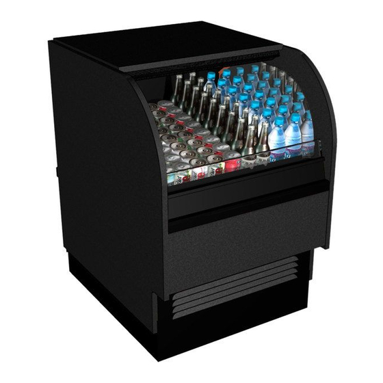
SELF-CONTAINED REFRIGERATED SERVICE/SELF-SERVICE MODEL CO2739R
Model CO2739R..................27 1/2"L* x 39"H x 33"D
*Includes end panels.
888 E. Porter Road · Muskegon, MI 49441 Phone: 231.798.8888 Fax: 231.798.4960 www.structuralconcepts.com
Rev D Date: 4.10.2012
I:\Oper Manuals\Oasis\CO27[L]R_99399.pub
Advertisement
Table of Contents

Related Manuals for Structural Concepts Oasis CO2739R


Summary of Contents for Structural Concepts Oasis CO2739R
- Page 1 M O B I L E S E R I E S SELF-CONTAINED REFRIGERATED SERVICE/SELF-SERVICE MODEL CO2739R Model CO2739R……………...27 1/2”L* x 39”H x 33”D *Includes end panels. 888 E. Porter Road · Muskegon, MI 49441 Phone: 231.798.8888 Fax: 231.798.4960 www.structuralconcepts.com Rev D Date: 4.10.2012...
-
Page 2: Table Of Contents
TABLE OF CONTENTS OVERVIEW / TYPE / COMPLIANCE / WARNINGS / PRECAUTIONS / PLUGS / WIRING ……..….. START-UP AND OPERATION ….…………...…...…..…………………………….…………….………… MAINTENANCE FUNDAMENTALS: FRONT PANEL / FRONT GRILLE / LIGHT FIXTURE ..……….… MAINTENANCE FUNDAMENTALS, CONTINUED: HONEYCOMB AIR DIFFUSERS …………………. ELECTRICAL & REFRIGERATION FUNDAMENTALS ………………………...……………….…………. REFRIGERATION FUNDAMENTALS ……………………………………………………………………….. -
Page 3: Overview / Type / Compliance / Warnings / Precautions / Plugs / Wiring - Page 1 Of 2
If unsure if unit is Type 1 or Type 2, see tag next to serial label. See SERIAL LABEL LOCATION & These Structural Concepts merchandisers are INFORMATION LISTED / TECH INFO & SERVICE designed to merchandise pre-chilled packaged section in this manual for sample serial labels. -
Page 4: Overview / Type / Compliance / Warnings / Precautions / Plugs / Wiring
OVERVIEW / TYPE / COMPLIANCE / WARNINGS / PRECAUTIONS / PLUGS / WIRING - PAGE 2 of 2 PRECAUTIONS WIRING DIAGRAM This sheet contains important precautions to prevent Each case has its own wiring diagram folded and in its damage to unit or merchandise. -
Page 5: Start-Up And Operation
START-UP AND OPERATION Merchandiser Start-Up Do not use an extension cord with this appliance. Main Power Switch Do not operate this equipment with a damaged cord, plug or outlet. Insure the main power switch is off. Plug cord into a certified 120V electrical outlet with ground. -
Page 6: Maintenance Fundamentals: Front Panel / Front Grille / Light Fixture
MAINTENANCE FUNDAMENTALS: FRONT PANEL / FRONT GRILLE / LIGHT FIXTURE 1. Removing the Front Panel Lifting the panel from lower edge upward Channel Lip approximately a half inch into a channel lip, disengages the support taps on the lower edges. Upper Front Panel ... -
Page 7: Maintenance Fundamentals, Continued: Honeycomb Air Diffusers
MAINTENANCE FUNDAMENTALS, CONTINUED: HONEYCOMB AIR DIFFUSERS Honeycomb Preventive maintenance should be performed Air Diffuser every 30 days unless conditions warrant a more frequent replacement cycle. Honeycomb Air Diffuser Removal Honeycomb is located in discharge air duct. A. Wedge a non-metallic device of suitable strength (such as a ballpoint pen) between the honeycomb and the end panel. -
Page 8: Electrical & Refrigeration Fundamentals
ELECTRICAL & REFRIGERATION FUNDAMENTALS 1. Electrical: Access and Connections Warning, disconnect power before providing maintenance and service to unit. Ballast 2. Light Ballast Access Remove three screws from the rear wire channel. Wire Channel Remove four screws from the rear grille. 3. -
Page 9: Refrigeration Fundamentals
If service is required to the temperature control unit, call Structural Concepts. This maintenance should be performed by a certified technician. 2. Evaporator Fan Access Remove lower decking. A finger hole is provided to assist in lifting up and pulling out deck. -
Page 10: Serial Label Location & Information Listed / Tech Info & Service
For additional technical information and service, see the TECHNICAL SERVICE page in this manual for instructions on contacting Structural Concepts’ Technical Service Department. See images below for samples of both refrigerated and non-refrigerated serial labels. -
Page 11: Troubleshooting
TROUBLESHOOTING Alarm Going Off See alarm and fault codes of temperature controller. Product is Drying Out Check the relative humidity in the store. Water on the Floor Check the drain trap is free of debris. Check that the condenser hot gas evaporator for cleanliness. - Page 12 TROUBLESHOOTING Not Holding Temperature If a large amount of warm product was added to the case, it will take time for the temperature to adjust. The temperature will change during defrost mode but will return to normal. Check that the case is not in the sun or near a heat or air-conditioning vent. Case may be located too near store’s outside doors.
-
Page 13: Illistrated Parts Breakdown
ILLUSTRATED PARTS BREAKDOWN... -
Page 14: Parts List
PARTS LIST Top Board Light Ballast End Panel Wire Channel End Panel Mirror Rear Grille Air Deflector Glass Temperature Controller Single Pole Switch Fan Motor, Evaporator Front Panel Deck Pan Bumper Insert Lamp Bulb Front Grille Honeycomb Bumper End Cap... -
Page 15: Cleaning Schedule
CLEANING SCHEDULE Cleaning Daily Weekly Monthly Task The acrylic must be cleaned with a mild soap and Clean Case Exterior water solution and a soft cloth. Never use a household cleaner on acrylic. Clean glass shelves and mirrors with a household or Clean Case Interior commercial glass cleaner. -
Page 16: Carel® Temperature Controller Information
Read And Save These Instructions - Page 1 of 3 Integrated Electronic Microprocessor Controller Programming The Instrument ▲ mute To Modify The Setpoint ▼ Press and hold the “SET” key for at least 1 second. 2. Use arrow keys ▲ ▼ on temperature ▲... - Page 17 Read And Save These Instructions - Page 2 of 3 Integrated Electronic Microprocessor Controller User Interface - Display Summary Table of Alarm and Signals: Display, Buzzer and Relay reset alarms w/manual reset / reset HACCP alarms / reset temp. monitoring...
- Page 18 Read And Save These Instructions - Page 3 of 3 Integrated Electronic Microprocessor Controller Summary Table of Operating Parameters CODE PARAMETER UOM* TYPE MINIMUM MAXIMUM DEFAULT Select Celsius (°C) or Fahrenheit (°F) flag Calibration of probe 1 °C/°F Calibration of probe 2 °C/°F For Case Specific...
-
Page 19: Johnson Control® - Mr3Ccuhv A
JOHNSON® CONTROL - MR3CCUHV larm and Fault Codes These alarm and fault codes will flash on the display when the control detects the following faults: Table 1: Error Codes and Status Error Code System Status Alarm output is on. Compressor runs according to the sensor failure mode selected (parameter SF). -
Page 20: Johnson Control® - Mr3Ccuhv Programming Control Module
JOHNSON® CONTROL - MR3CCUHV Defrost Compressor Status Status Status Manual Defrost Button Button Enter Down Button Button To Lock and Unlock The Unit for Programming To Program Values Other Than The Setpoint Press the Enter, Up, and A parameter settings reference page is included in Table 3 Down buttons in sequence of this bulletin. -
Page 21: Scc Technical Service Contact Information & Warranty Information
LIMITED WARRANTY All sales by Structural Concepts Corporation (SCC) are subject to the following limited warranty. “Goods” refers to the product or products being sold by SCC. Warranty Scope: Warranty is for equipment sold in the United States, Canada, Mexico and Puerto Rico. Equipment sold elsewhere may carry modified warranty.
Need help?
Do you have a question about the Oasis CO2739R and is the answer not in the manual?
Questions and answers