Table of Contents
Advertisement
Quick Links
- 1 Overview / Type / Compliance / Warnings / Precautions / Wiring Diagram - Page 1 of 2
- 2 Remote Cases: Refrigeration Line Field Connection
- 3 Field Wiring Box / Data Collection Cable / Main Power Switch
- 4 Troubleshooting (to be Performed by Store Personnel)
- 5 Troubleshooting (to be Performed by Trained Service Providers Only)
- Download this manual
INSTALLATION &
OPERATING MANUAL
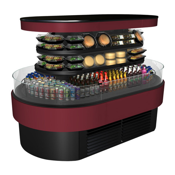
> REFRIGERATED SELF-SERVICE ISLAND - CID MODELS FSI856R, FSI656R, FSI663R and FSI863R
> REFRIGERATED SELF-SERVICE PENINSULA END CAP - CID MODEL FSE663R
Model FSE663R
Model FSI656R
Specialty / Refrig Self-Svc Island & End Cap CID Case Manual_20-20438.pub
READ AND SAVE THESE INSTRUCTIONS
888 E. Porter Road · Muskegon, MI 49441 Phone: 231.798.8888 Fax: 231.798.4960 www.structuralconcepts.com
SCC P/N
20-20438
Model FSI863R
Model FSI663R
Rev J Date: 5.1.2017
Advertisement
Table of Contents
Troubleshooting

Subscribe to Our Youtube Channel
Related Manuals for Structural Concepts FSI856R


Summary of Contents for Structural Concepts FSI856R
- Page 1 READ AND SAVE THESE INSTRUCTIONS INSTALLATION & SCC P/N OPERATING MANUAL 20-20438 > REFRIGERATED SELF-SERVICE ISLAND - CID MODELS FSI856R, FSI656R, FSI663R and FSI863R > REFRIGERATED SELF-SERVICE PENINSULA END CAP - CID MODEL FSE663R Model FSI863R Model FSE663R Model FSI656R Model FSI663R 888 E.
-
Page 2: Table Of Contents
TABLE OF CONTENTS OVERVIEW / TYPE / COMPLIANCE / WARNINGS / PRECAUTIONS / WIRING DIAGRAM ....SHIPPING BRACKET PURPOSE / REMOVAL METHOD and DISPOSAL ……………………………. KICK PANEL REMOVAL / REMOVAL OF CASE FROM PALLET / POSITIONING UNIT ………..…. LEVELING UNIT / SHIMMING FRAME SUPPORT RAILS (REMOTE UNITS ONLY) …………..…. CASTER SYSTEM (OPTIONAL) / LEVELERS (SELF-CONTAINED UNITS ONLY) ...……………….. -
Page 3: Overview / Type / Compliance / Warnings / Precautions / Wiring Diagram - Page 1 Of 2
COMPLIANCE Performance issues when in violation of applicable These Structural Concepts merchandisers are NEC, federal, state and local electrical and plumbing designed to merchandise packaged products at 41 °F codes are not covered by warranty. (5 °C) or less product temperatures. - Page 4 OVERVIEW / TYPE / COMPLIANCE / WARNINGS / PRECAUTIONS / WIRING DIAGRAM - PAGE 2 of 2 PRECAUTIONS WIRING DIAGRAM This sheet contains important precautions to prevent Each case has its own wiring diagram folded and in damage to unit or merchandise. its own packet.
-
Page 5: Shipping Bracket Purpose / Removal Method And Disposal
SHIPPING BRACKET PURPOSE / REMOVAL METHOD and DISPOSAL / SHIPPING BRACE REMOVAL Either discard or recycle. 1. Shipping Bracket Purpose See illustration below. Shipping brackets are designed to secure condenser package during shipment. 3. Shipping Brace For In-Line Casters ... -
Page 6: Kick Panel Removal / Removal Of Case From Pallet / Positioning Unit
KICK PANEL REMOVAL / REMOVAL OF CASE FROM PALLET / POSITIONING UNIT 3. J-Bar or Dolly Only (No Fork Lift) 1. Note: Kick Panels Are NOT To Be On Case During Removal From Pallet! Slide case to edge of pallet. ... -
Page 7: Leveling Unit / Shimming Frame Support Rails (Remote Units Only)
LEVELING UNIT / SHIMMING FRAME SUPPORT RAILS (REMOTE UNITS ONLY) Leveling Unit / Shimming Frame Support Illustration below shows case with frame support rails. Rails (Remote Units Only) Note: After case has been properly shimmed, Case must be leveled to assure proper operation. attach panels. -
Page 8: Caster System (Optional) / Levelers (Self-Contained Units Only)
CASTER SYSTEM (OPTIONAL) / LEVELERS (SELF-CONTAINED UNITS ONLY) 1. Caster System (Optional) 3. Raise Levelers Certain cases have a caster system that allows Levelers may be raised to allow case to be slid to case to be slid in and out of position. new location. -
Page 9: Ceiling Originated Electrical & Refrigeration Lines / Knockout Removal
Caution! If ceiling originated lines are used, you 1. Merchandiser Versatility MUST seal both upper and lower PVC pass- Structural Concepts cases can accompany throughs (at entrance points) with expandable either floor or ceiling originated electrical and/or foam sealant to prevent condensation in case. -
Page 10: Remote Cases: Refrigeration Line Field Connection
REMOTE CASES: REFRIGERATION LINE FIELD CONNECTION 2. Refrigeration Lines at Underside 1. Refrigeration Line Field Connection Underside refrigeration lines are standard. Warning! Turn power off and/or disconnect Refrigeration lines are ALWAYS at rear of case. power before providing maintenance and ... -
Page 11: Remote Cases: Condensate Pump Location And Purpose
REMOTE CASES: CONDENSATE PUMP LOCATION AND PURPOSE 2. Condensate Pump Purpose 1. Condensate Pump Location Condensate pump is to be used when no floor Warning! Turn power off and/or disconnect power before providing maintenance and drain is available. service to unit. -
Page 12: Field Wiring Box / Data Collection Cable / Main Power Switch
FIELD WIRING BOX / DATA COLLECTION CABLE / MAIN POWER SWITCH 1. Field Wiring Box / Data Collection Box 3. Self-Contained Cases Only: Main Power Access Switch Warning! Turn power off and/or disconnect For self-contained cases, the main power switch power before providing maintenance and controls power to entire case. -
Page 13: Self-Contained Units: Toe-Kick Attachment Instructions (Horiz. Vs. Vertical)
SELF-CONTAINED UNITS: TOE-KICK ATTACHMENT INSTRUCTIONS (HORIZONTAL vs. VERTICAL) Self-Contained Units: Toe-Kick Attachment Instructions Toe-kick venting designs vary depending upon whether it is located at Note: Illustrations intake or discharge side of case. Shown May Not Proper airflow will be maintained by following these instructions: Exactly Reflect Every A. -
Page 14: Plan-O-Gram (Load Level Guidelines)
PLAN-O-GRAM (LOAD LEVEL GUIDELINES): FROM SCC P/N 20-24592 Plan-O-Gram (Load Level Guidelines) > Note: Any changes to this sheet must also be made to SCC P/N 20-24592 CAUTION! TO MAINTAIN SAFE PRODUCT TEMPERATURES & AIRFLOW: DO NOT STACK PRODUCT NEARER THAN 1” TO UNDERSIDE OF FASCIA ... -
Page 15: Thermometers (Digital Thermometer & Optional "Check Temperature")
THERMOMETERS (DIGITAL THERMOMETER & OPTIONAL “CHECK TEMPERATURE”) Thermometers Thermometers are located on rear plenum at upper area of case. Digital thermometer is on ALL merchandisers. The “Check Temperature” thermometer is optional. See illustrations below. Illustration Shown May Not Exactly Reflect Every Digital Optional “Check... -
Page 16: Power-Up Check (Evaporator Fan Area)
POWER-UP CHECK (EVAPORATOR FAN AREA) Power-Up Check (Evaporator Fan Area) After power has been supplied, evaporator coil fans will be operational. To verify fans are operational, lift up deck pans; check to see that the coil fans are all functioning properly. -
Page 17: Maintenance Fundamentals: Shelf & Bracket Assembly Removal
MAINTENANCE FUNDAMENTALS: SHELF & BRACKET ASSEMBLY REMOVAL 1. Shelf & Bracket Assembly Removal Shelving is fixed; it is not adjustable. Screws must be removed to remove shelves. See illustrations below. -
Page 18: Maintenance Fundamentals: Led Light Fixtures / Removal / Replacement
MAINTENANCE FUNDAMENTALS, CONTINUED: LED LIGHT FIXTURES / REMOVAL / REPLACEMENT 2. LED Light Switch LED light switch to entire case is always located in upper section of the case. See illustration at top-right. 3. LED Light Fixtures Light fixtures are always located in upper section of the case. -
Page 19: Refrigeration Fundamentals: Remote Drain Layout
RERIGERATION FUNDAMENTALS: REMOTE DRAIN LAYOUT Remote Unit Refrigeration Line Access, Connections & Servicing To Be Accomplished By Licensed Contractors Only Illustration below shows location of refrigeration lines for remote connection. Two (2) drains accessible from top of unit by lifting up decking. ... -
Page 20: Refrigeration Fundamentals: Self-Contained Drain Layout
REFRIGERATION FUNDAMENTALS: SELF-CONTAINED DRAIN LAYOUT Self-Contained Refrigeration Line Access, Connections & Servicing To Be Accomplished By Licensed Contractors Only Illustration below shows location of refrigeration lines for self-contained operation. Four (4) drains accessible from top of unit by lifting up decking. ... -
Page 21: Refrigeration Fundamentals: Condensate Package Access
REFRIGERATION FUNDAMENTALS: CONDENSATE PACKAGE ACCESS Self-Contained Units: Access to Condensate Refrigerant lines are flexible to facilitate Package condensate package being slid out from case. Plastic glides are mounted at base to assist in Assembly/disassembly and servicing to be sliding the condenser out for access. -
Page 22: Refrigeration Fundamentals: Condensate Package Illustrated Parts Breakdown
REFRIGERATION FUNDAMENTALS: CONDENSATE PACKAGE ILLUSTRATED PARTS BREAKDOWN Self-Contained Unit’s Condensate Package Condensate Package Configuration Illustrated Parts Breakdown Illustration shown is from model FSI863R. Your unit’s component layout may slightly vary. Assembly/disassembly and servicing to be Note: As shown in illustration below, condensate performed by licensed refrigeration contractor. -
Page 23: General Cleaning (By Store Personnel)
GENERAL CLEANING (TO BE PERFORMED BY STORE PERSONNEL) FREQ. AREA / INSTRUCTIONS Daily Acrylic Air Deflectors (See Illustration Below): Use WASH spray bottle on air deflectors. Wipe off residue with paper towel. Use RINSE spray bottle on air deflectors. Dry with paper towel. Daily Stainless Steel Mirrors: Use stainless steel cleaner or glass cleaner on surface to remove finger prints and smudges. -
Page 24: General Cleaning (By Store Personnel) - Condenser Coil Air Filter
GENERAL CLEANING (TO BE PERFORMED BY STORE PERSONNEL) - CONDENSER COIL AIR FILTER Weekly Condenser Coil Air Filter Cleaning: off excess dust particles and debris from filter. DO NOT use rags or cloths. A magnetized air filter is attached to the inside of 4. -
Page 25: Preventive Maintenance
PREVENTIVE MAINTENANCE (TO BE PERFORMED BY TRAINED SERVICE PROVIDERS ONLY) WARNING! TURN OFF CASE BEFORE PERFORMING PREVENTIVE MAINTENANCE! FREQ. AREA / INSTRUCTIONS Quarterly Tub, Coil, Drain, Evaporator Fan Blades, Motors, Brackets: Disconnect power from the case before cleaning the tub, coil, fan, motor and drain area! ... -
Page 26: Trained Service Providers Only)
PREVENTIVE MAINTENANCE: HONEYCOMB (PERFORMED BY TRAINED SERVICE PROVIDERS ONLY) debris and stubborn or sticky residue. Use spray nozzle 1. Honeycomb Air Diffuser Removal on pot sink or use RINSE spray bottle on honeycomb. A. Wedge non-metallic device of suitable strength (such Allow honeycomb to air dry or use vacuum ‘blow mode’. -
Page 27: Troubleshooting (To Be Performed By Store Personnel)
TROUBLESHOOTING (TO BE PERFORMED BY STORE PERSONNEL*) CONDITION TROUBLESHOOTING Water Is On The Floor Check that drain at underside of case is properly routed to floor drain (remote cases) or evaporator pan (self-contained units). Call service provider. Fans Emit Excessive Noise Call service provider. -
Page 28: Troubleshooting (To Be Performed By Trained Service Providers Only)
TROUBLESHOOTING (TO BE PERFORMED BY TRAINED SERVICE PROVIDERS ONLY) CONDITION TROUBLESHOOTING Water Is On The Floor Check that the drain trap is free of debris. Check that the drain hose is correctly positioned over floor drain. Remote units condensate pump: Check that unit is operating properly. Check store conditions. -
Page 29: Troubleshooting (To Be Performed By Trained Service Providers Only)
TROUBLESHOOTING (TO BE PERFORMED BY TRAINED SERVICE PROVIDERS ONLY), CONTINUED CONDITION TROUBLESHOOTING Case Lights Are Not Follow previous page’s System Not Operating instructions. Working Check voltage at LED driver. If voltage is entering but not exiting, LED driver may be faulty. Check connection at front of case (from circuit breaker) for voltage. -
Page 30: Troubleshooting: Condensing System (By Trained Service Providers Only)
TROUBLESHOOTING - CONDENSING SYSTEM (BY TRAINED SERVICE PROVIDERS ONLY) CONDITION TROUBLESHOOTING Head Pressure Too High Check that the condensing coil is not dirty or covered. Check that condensing fans are working. Check that refrigerant is not overcharged. Perform sub-cooling check and verify that no contaminates are in system. Check that liquid line filter dryer is not plugged. -
Page 31: Troubleshooting: Evaporator System (By Trained Service Providers Only)
TROUBLESHOOTING - EVAPORATOR SYSTEM (BY TRAINED SERVICE PROVIDERS ONLY) CONDITION TROUBLESHOOTING Low Suction Pressure Check if sight glass is flashing or showing low charge. Check that expansion valve (TXV) isn’t restricted. Check element charge. Check that liquid line or filter isn’t restricted. Check that refrigeration lines and/or hoses are not kinked on either high or low sides. -
Page 32: Serial Label Location & Information Listed / Tech Info & Service
For additional technical information and service, see the TECHNICAL SERVICE page in this manual for instructions on contacting Structural Concepts’ Technical Service Department. See images below for samples of both refrigerated and non-refrigerated serial labels. -
Page 33: Carel® Controller: Programming The Instrument
Read And Save These Instructions - Page 1 of 3 Integrated Electronic Microprocessor Controller Programming The Instrument ▲ mute To Modify The Setpoint ▼ 1. Press and hold the “SET” key for at least 1 second. 2. Use arrow keys ▲ ▼ on temperature ▲... -
Page 34: Carel® Controller: User Interface, Summary Tables Of Alarms & Signals
Read And Save These Instructions - Page 2 of 3 Integrated Electronic Microprocessor Controller User Interface - Display Summary Table of Alarm and Signals: Display, Buzzer and Relay reset alarms w/manual reset / reset HACCP alarms / reset temp. monitoring... -
Page 35: Carel® Controller: Summary Table Of Operating Parameters (After Programming Key)
Read And Save These Instructions - Page 3 of 3 Integrated Electronic Microprocessor Controller Summary Table of Operating Parameters CODE PARAMETER UOM* TYPE MINIMUM MAXIMUM DEFAULT Select Celsius (°C) or Fahrenheit (°F) flag Calibration of probe 1 °C/°F Calibration of probe 2 °C/°F For Case Specific... -
Page 36: Technical Service Contact Information & Warranty Information
LIMITED WARRANTY All sales by Structural Concepts Corporation (SCC) are subject to the following limited warranty. “Goods” refers to the product or products being sold by SCC. Warranty Scope: Warranty is for equipment sold in the United States, Canada, Mexico and Puerto Rico. Equipment sold elsewhere may carry modified warranty.
Need help?
Do you have a question about the FSI856R and is the answer not in the manual?
Questions and answers