Table of Contents
Advertisement
Quick Links
READ AND SAVE THESE INSTRUCTIONS
INSTALLATION
SCC P/N
& OPERATING
20-80692
MANUAL
REVEAL™ FREE STANDING SERVICE REFRIGERATED MERCHANDISERS
> REAR SLIDING DOORS > SELF-CONTAINED OR REMOTE UNITS
> CAUTION! DO NOT PUSH OR PULL ON UPPER GLASS ENCLOSURE!
> ONLY USE HANDLES (AT EACH END OF CASE) TO PUSH OR PULL CASE INTO POSITION!
> SEE PAGE 3 FOR THIS OPERATING MANUAL'S MODEL APPLICABILITY AND DIMENSIONS
> SEE PAGE 8 FOR FRONT PANEL, SIDE CLADDING, AIR INTAKE GRILLE & FRONT TOE-KICK
ATTACHMENT INSTRUCTIONS
Models Are Shipped WITHOUT Panels
and Cladding Attached. See Page 8 For
Component Attachment Instructions.
Model NR3655RSV Free Standing Unit Shown
Before Front/Side Cladding and Toe-Kick
Have Been Attached
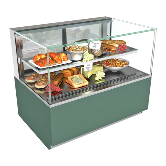
Model NR3655RSV Free Standing Unit
Shown After Front/Side Cladding and
Toe-Kick Have Been Attached
Structural Concepts Corporation · 888 E. Porter Road · Muskegon, MI 49441 Phone: 231.798.8888 Fax: 231.798.4960 · www.structuralconcepts.com
Rev A Date: 6.13.2017
I:\Manuals\Reveal_Free Standing_Refrig Service Cases 20-80692.pub
Advertisement
Table of Contents
Troubleshooting

Related Manuals for Structural Concepts REVEAL Series


Summary of Contents for Structural Concepts REVEAL Series
- Page 1 Model NR3655RSV Free Standing Unit Shown After Front/Side Cladding and Toe-Kick Have Been Attached Structural Concepts Corporation · 888 E. Porter Road · Muskegon, MI 49441 Phone: 231.798.8888 Fax: 231.798.4960 · www.structuralconcepts.com Rev A Date: 6.13.2017 I:\Manuals\Reveal_Free Standing_Refrig Service Cases 20-80692.pub...
-
Page 2: Table Of Contents
TABLE OF CONTENTS TABLE OF CONTENTS …………………………………………………………………………………...…... REVEAL™ FREE STANDING REFRIGERATED SERVICE MODEL APPLICABILITY & DIMENSIONS ……………………………………………………………………………………….….. OVERVIEW / DISPLAY TYPE I vs. II / COMPLIANCE / WARNINGS / PRECAUTIONS ……………... INSTALLATION: TOE-KICK & AIR INTAKE GRILLE REMOVAL / DISCONNECTING CASE FROM PALLET ...…...………………………………………………………………………………….………. -
Page 3: Reveal™ Free Standing Refrigerated Service Model Applicability
REVEAL™ FREE STANDING REFRIGERATED SERVICE MODEL APPLICABILITY & DIMS. Upper Display Model Overall Case Height Case Depth x Width Case Height NR3633RSV 13 5/8” 32 7/8” 33”D* x 35 3/4”W NR3640RSV 20 3/8” 39 5/8” 33”D* x 35 3/4”W NR3647RSV 27 7/8”... -
Page 4: Overview / Display Type I Vs. Ii / Compliance / Warnings / Precautions - Page 1 Of 2
80 °F (27 °C) and 55% maximum humidity. These Structural Concepts Reveal™ cases are If unsure if your unit is Type I or II, see tag next to serial designed to merchandise packaged products at 40°F label. - Page 5 OVERVIEW / DISPLAY TYPE I vs. II / COMPLIANCE / WARNINGS / PRECAUTIONS - PAGE 2 of 2 PRECAUTIONS WIRING DIAGRAM Following are important precautions to prevent Each case has its own wiring diagram folded and in its own damage to unit or merchandise.
-
Page 6: Installation: Toe-Kick & Air Intake Grille Removal / Disconnecting Case From
INSTALLATION: TOE-KICK & AIR INTAKE GRILLE REMOVAL / DISCONNECTING CASE FROM PALLET 1. Remove Front Toe-Kick From Case To prevent damage to case, remove front toe-kick from case before removing from pallet. Toe-kick is held in place by magnets only. No screw removal is required. -
Page 7: Installation, Cont'd.: Caster Adjustment / Lock / Unlock / Case Removal From Pallet
INSTALLATION, CONT’D.: CASTER ADJUSTMENT / LOCK / UNLOCK / CASE REMOVAL FROM PALLET 4. Caster Height: Raising and Lowering Vertical Raise or lower casters (to adjust case height) by Adjustment rotating casters’ vertical adjustment rings. Ring Rotate vertical adjustment ring clockwise to lower caster (and increase height of case). -
Page 8: Components (Cladding, Front Toe-Kick, Front Panel, Grille, Etc.)
INSTALLATION, CONT’D: REMOVE SHIPPING BRACE AND HANDLES / ATTACH COMPONENTS 8. Remove Handles On Sides of Case Then, slide panel into case until magnets attach to case in flange’s cutout openings (as shown). When case has been moved into position, remove ... -
Page 9: Installation, Cont'd: Bracket Retainers / Shelving Assembly Components
INSTALLATION, CONT’D: BRACKET RETAINERS / SHELVING ASSEMBLY COMPONENTS 11. Nylon Shipping Bracket Retainers There are eight (8) components comprising each shelf assembly: Retainers keep shelving secure during shipping. 1. Right bracket (with hooks to attach to slots in ... -
Page 10: Installation, Cont'd: Plug In Unit / Main Power Switch
INSTALLATION, CONT’D: PLUG IN UNIT / MAIN POWER SWITCH 13. Plug Case In / Turn Main Power Switch On Factory-Supplied Power Cord With Plug Power cord with plug is factory-supplied. Plug case into customer-supplied electrical outlet. Note 1: Partially-disassembled view at right is shown with casters removed for illustrative purposes only. -
Page 11: Case Design: Front View Of Free Standing, Service Merchandisers
CASE DESIGN: FRONT VIEW OF FREE STANDING, SERVICE MERCHANDISERS 1. Case Design: Front View Of Free Standing, Service Merchandisers Model NE3635RSV is illustrated below. Air intake grille, side cladding, front base kick & front panel have been removed for illustrative purposes only. -
Page 12: Case Design: Rear View Of Free Standing, Service Merchandisers
CASE DESIGN: REAR VIEW OF FREE STANDING, SERVICE MERCHANDISERS 2. Case Design: Rear View Of Free Standing, Service Merchandisers Model NR4855RSV free standing unit is illustrated below. Air intake grille, rear panel, side cladding & shipping brace have been removed for illustrative purposes only. -
Page 13: Case Design, Cont'd: Controller / Dc Drivers / Main Power Switch
CASE DESIGN, CONT’D: CONTROLLER / DC DRIVERS / MAIN POWER SWITCH / COIL FILTER Remove 4 screws from the controller/DC 3. Case Design: Controller / DC Driver Access / driver box cover to access electrical Components components. Remove front panel by lifting up and off; no screw ... -
Page 14: Case Design, Cont'd: Tub Area (After Deck Pan Removal)
CASE DESIGN, CONT’D: TUB AREA (AFTER DECK PAN REMOVAL) 4. Case Design, Cont’d: Tub Area (After Deck Pan Removal) Note: Refrigeration service to be accomplished by refrigeration / electrical contractors only. Caution! Turn main power off before accessing tub area. ... -
Page 15: Case Design, Cont'd: Led Lights / Led Light Switch / Thermometer
CASE DESIGN, CONT’D: LED LIGHTS / LED LIGHT SWITCH / THERMOMETER 7. Thermometer Function & Placement 5. Case Design, Cont’d: LED Lights / LED Light Switch Thermometer provides temperature of refrigerated section of case. LED lights are located at both header and ... -
Page 16: Case Design, Cont'd: Rear Sliding Door Removal / Replacement
CASE DESIGN, CONT’D: REAR SLIDING DOOR REMOVAL / REPLACEMENT 8. Rear Sliding Door Removal / Replacement To remove rear sliding doors, move rear doors toward center of the case. Individually lift each door up toward the top of the case; pivot the bottom of the door out. ... -
Page 17: Case Design, Cont'd: Condenser Package (Self-Contained Units Only)
CASE DESIGN, CONT’D: CONDENSER PACKAGE (SELF-CONTAINED UNITS ONLY) 9. Condenser Package (Self-Contained Units Condensate Package Configuration Only) Illustration shown is from model NR3635RSV. Your unit’s component layout may slightly vary. Assembly/disassembly and servicing to be performed by licensed refrigeration contractor. Condenser Coil Optional Clean Fans &... -
Page 18: Product Placement / Airflow Consideration / Load Lines
START-UP AND OPERATION, CONTINUED: LOAD LIMITS PRODUCT PLACEMENT / AIRFLOW CONSIDERATION / LOAD LINES Caution! For airflow to reach return air grille, you 1. Product Placement must not block front or rear grilles with product. Product can be placed on decking or steps ... -
Page 19: Cleaning Schedule (To Be Performed By Store Personnel)
CLEANING SCHEDULE (TO BE PERFORMED BY STORE PERSONNEL) FREQ. INSTRUCTIONS Daily Glass Surfaces: Clean side glass and shelves with household or commercial glass cleaner. Daily Rear Sliding Door Exterior Glass: Clean with household or commercial glass cleaner. Clean out rear door track with moist cloth. Daily End Panels, Front Panel, Toe-Kick, etc.: Wipe off all surfaces with warm water and mild soap solution and non-abrasive cloth. -
Page 20: Preventive Maintenance (To Be Performed By Trained Service Provider) - Page 1 Of 2
PREVENTIVE MAINTENANCE (TO BE PERFORMED BY TRAINED SERVICE PROVIDER) - PAGE 1 OF 2 WARNING! TURN OFF CASE BEFORE PERFORMING PREVENTIVE MAINTENANCE! FREQ. INSTRUCTIONS Quarterly Condensing Coil: Remove air intake grille to access area. Simply lift up and off. ... - Page 21 PREVENTIVE MAINTENANCE (TO BE PERFORMED BY TRAINED SERVICE PROVIDER) - PAGE 2 OF 2 FREQUENCY INSTRUCTIONS Quarterly Optional Clean Sweep™ Condensing Coil Cleaner: Disconnect power from case before servicing the Clean Sweep™ Condenser Coil Cleaner! Remove air intake grille (by lifting up and off); no screw removal is required. ...
-
Page 22: Troubleshooting (To Be Performed By Store Personnel Only)
TROUBLESHOOTING (TO BE PERFORMED BY STORE PERSONNEL) - PAGE 1 OF 2 CONDITION TROUBLESHOOTING Water Is On The Floor Call service provider. Fan Emits Excessive Noise Call service provider. Case Lights Are Not Working Check that light switch is in the on position. Check that ALL of the light cords and plugs are properly connected. - Page 23 TROUBLESHOOTING (TO BE PERFORMED BY STORE PERSONNEL) - PAGE 2 OF 2 LED Light Fixture Replacement Note: LED light and plug must be connected in a specific manner or they will not work. Light fixtures are located in header as well as in ...
-
Page 24: Troubleshooting (To Be Performed By Trained Service Providers Only) - Page 1 Of 3
TROUBLESHOOTING (TO BE PERFORMED BY TRAINED SERVICE PROVIDERS ONLY) - PAGE 1 OF 3 CONDITION TROUBLESHOOTING Water Is On The Caution! Disruption of power or malfunctioning condensate pan (or electric coil overflow condensate pan) may cause water to overflow pan and seep onto flooring Floor causing damage! Until condensate pan(s) are functioning (or are replaced), follow these procedures:... -
Page 25: Troubleshooting (To Be Performed By Trained Service Providers Only), Page 2 Of 3
TROUBLESHOOTING (TO BE PERFORMED BY TRAINED SERVICE PROVIDERS ONLY), PAGE 2 OF 3 CONDITION TROUBLESHOOTING Fans Emit Check that the case is aligned, level and plumb. Excessive Noise Check evaporator fans for cleanliness. Unplug/power off fan motors. Check motor shaft for bearing wear. Check that fan motors are securely mounted in brackets. - Page 26 TROUBLESHOOTING (TO BE PERFORMED BY TRAINED SERVICE PROVIDERS ONLY), PAGE 3 OF 3 CONDITION TROUBLESHOOTING Case Lights Are Check that light switch is in the on position. Not Working Check that ALL of the light cords and plugs are properly connected. See TROUBLESHOOTING (TO BE PERFORMED BY STORE PERSONNEL) - PAGE 2 OF 2 in operating manual for illustrations.
-
Page 27: Condensing System
TROUBLESHOOTING (BY TRAINED SERVICE PROVIDERS ONLY) - CONDENSING SYSTEM CONDITION TROUBLESHOOTING Head Pressure Check that the condensing coil is not dirty or covered. Too High Check that condensing fans are working. Check that refrigerant is not overcharged. Perform sub-cooling check and verify that no contaminates are in system. Check that liquid line filter dryer is not plugged. -
Page 28: Evaporator System
TROUBLESHOOTING (BY TRAINED SERVICE PROVIDERS ONLY) - EVAPORATOR SYSTEM CONDITION TROUBLESHOOTING Check if sight glass is flashing or showing low charge. Low Suction Pressure Check that expansion valve (TXV) isn’t restricted. Check element charge. Check that liquid line or filter isn’t restricted. Check that refrigeration lines and/or hoses are not kinked on either high or low sides. -
Page 29: Serial Label Information & Location
For additional technical information and service, see the TECHNICAL SERVICE page in this For additional technical information and service, see the TECHNICAL SERVICE page in this manual for instructions on contacting Structural Concepts’ Technical Service Department. manual for instructions on contacting Structural Concepts’ Technical Service Department. -
Page 30: Temperature Controller - Carel
▲ Press and hold the “aux” key for 1 second. Structural Concepts Corp., 888 E. Porter Rd · Muskegon, MI 49441 I:\Oper Manuals - PUB\Templates\Carel Controller\Carel Controller IR33.pub This data derived from Carel Material: ir33 +030220441 - rel. 2.0 - 01.05.2006... - Page 31 Summary Table of Alarm and Signals: Display, Buzzer and Relay reset alarms w/manual reset / reset HACCP alarms / reset temp. monitoring Structural Concepts Corp., 888 E. Porter Rd · Muskegon, MI 49441 I:\Oper Manuals - PUB\Templates\Carel Controller\Carel Controller IR33.pub Ph: 231.798.8888 / Fax: 231-798-0393 / www.structuralconcepts.com...
- Page 32 Display of defrost probe 1 °C/°F * Unit Of Measure Structural Concepts Corp., 888 E. Porter Rd · Muskegon, MI 49441 I:\Oper Manuals - PUB\Templates\Carel Controller\Carel Controller IR33.pub Ph: 231.798.8888 / Fax: 231-798-0393 / www.structuralconcepts.com This data derived from Carel Material: ir33 +030220441 - rel. 2.0 - 01.05.2006...
-
Page 33: Technical Service Contact Information & Warranty Information
LIMITED WARRANTY All sales by Structural Concepts Corporation (SCC) are subject to the following limited warranty. “Goods” refers to the product or products being sold by SCC. Warranty Scope: Warranty is for equipment sold in the United States, Canada, Mexico and Puerto Rico. Equipment sold elsewhere may carry modified warranty.
Need help?
Do you have a question about the REVEAL Series and is the answer not in the manual?
Questions and answers