Table of Contents
Advertisement
Quick Links
- 1 Table of Contents
- 2 Start-Up and Operation
- 3 Troubleshooting: General Overview
- 4 Troubleshooting: Condensing System (by Trained Service Providers Only)
- 5 Troubleshooting: Evaporator System (by Trained Service Providers Only)
- 6 Troubleshooting: Compressor Not on / no Display on Controller
- 7 Carel® Controller - Programming the Instrument
- Download this manual
READ AND SAVE THESE INSTRUCTIONS
INSTALLATION AND
PN 54190
OPERATING MANUAL
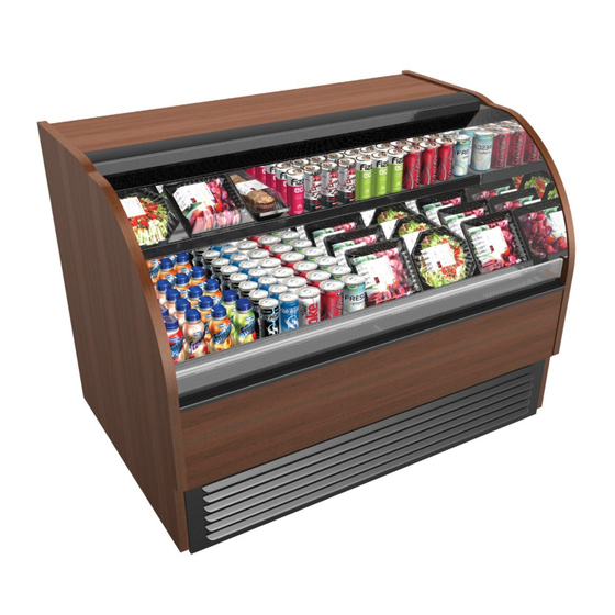
SELF-SERVICE REFRIGERATED BAKERY MERCHANDISER
HMO7536R
HMO7536R (Shown With
Optional Security Grid)
HMO3936R
HMO4836R.5936 (With Ambient
Upper Glass Enclosure) /
Product Shown For Illustrative
Purposes Only
HMO5136R.7121 (Similar To
HMO3936R.7121) With Ambient
Upper Glass Enclosure & Acrylic Bins
Models To Which This Manual Is Applicable*
HMO5136R.4716 (With Steps)
HMO3936R, HMO3936R.7121, HMO4836R.5936 / HMO5136R.4716,
HMO5136R.7121, HMO7236R.4716A and HMO7536R
* Note: This Manual May Also Be Applicable To Models Not Listed Herein.
888 E. Porter Road · Muskegon, MI 49441 Phone: 231.798.8888 Fax: 231.798.4960 www.structuralconcepts.com
I:\Oper Manuals - PUB\Harmony\HMO(L)36R_4716_4716A_5936_54190.pub
Rev O Date: 10.27.2016
Advertisement
Table of Contents
Troubleshooting

Related Manuals for Structural Concepts Harmony HMO7536R


Summary of Contents for Structural Concepts Harmony HMO7536R
- Page 1 READ AND SAVE THESE INSTRUCTIONS INSTALLATION AND PN 54190 OPERATING MANUAL SELF-SERVICE REFRIGERATED BAKERY MERCHANDISER HMO7536R HMO7536R (Shown With Optional Security Grid) HMO3936R HMO4836R.5936 (With Ambient Upper Glass Enclosure) / Product Shown For Illustrative Purposes Only HMO5136R.7121 (Similar To HMO3936R.7121) With Ambient Upper Glass Enclosure &...
-
Page 2: Table Of Contents
TABLE OF CONTENTS OVERVIEW AND WARNINGS ……..………………..…….………………………..…………………..….. CASE REMOVAL FROM SKID (LEVELERS OR CASTERS) ……………………………………………... INSTALLATION …………………………………………………………………..……...………………..……. 6-10 POSITIONING, ALIGNING, LEVELING UNIT, REMOVING FRONT GRILLE …..………………………. START-UP AND OPERATION ……...….…………...…...…..………………………...………….……..…… MAINTENANCE FUNDAMENTALS - SHELF ASSEMBLY / LIGHT FIXTURES ..…………………..…... MAINTENANCE FUNDAMENTALS - STEP ASS’Y / LED LIGHT FIXTURE & POWER SUPPLY ACCESS …………..……………………………………………………………………………...……. -
Page 3: Overview And Warnings
OVERVIEW maintained within a specific range. These Structural Concepts merchandisers are For Type 1 Conditions (these cases) ambient designed to merchandise packaged products at 41 °F conditions are to be at 55% maximum humidity and (5 °C) or less product temperatures. - Page 4 OVERVIEW / TYPE / COMPLIANCE / WARNINGS / PRECAUTIONS / WIRING / PLUGS - PAGE 2 of 2 PRECAUTIONS WIRING DIAGRAM This sheet contains important precautions to prevent Each case has its own wiring diagram folded and in its damage to unit or merchandise.
-
Page 5: Case Removal From Skid (Levelers Or Casters)
CASE REMOVAL FROM SKID (LEVELERS OR CASTERS) 1. Removing Case Shipping Brackets That Are Attached To Skid Remove screws holding Case Shipping Brackets to skid. Remove Case Shipping Brackets from Skid. See illustrations below. Note: Shipping Brackets will vary in size, shape, material and location depending upon case type and model. -
Page 6: Installation
INSTALLATION Installation Note: Units shown may not depict an exact representation of your particular unit being installed. 1. Position and Level Units Position Units. Align multiple units carefully in areas A, B, and C. 2. Bolting Units Together Bolt units together at holes indicated at right. Note: View at right has shelving removed for illustrative purposes only. - Page 7 INSTALLATION, CONTINUED 3. Electrical Connections (Remote Cases) Field wiring connection / electrical access location is at customer-left side of case. Single phase leads are provided. Connection 4. Connections/Controller/Main Power Switch (Self-Contained Units) Controller/Ballast box is at customer rear. ...
- Page 8 INSTALLATION, CONTINUED 5. Electrical Connections (Certain Remote Cases) Field wiring connection / electrical access location is at Case Rear customer-left side of case. Single phase leads are provided. 6. Evaporator Fan Area Illustration below shows front of case with decking removed.
- Page 9 INSTALLATION, CONTINUED 7. Honeycomb Air Diffuser Remove the two most forward screws; panel must hang down supported by the rear screws. Honeycomb is located in discharge air duct. Do not force panel lower. From inside lower refrigerated area, locate the ...
- Page 10 INSTALLATION, CONTINUED 8. Risers (aka “Step Assemblies”) Risers allow product to be more prominently displayed. Risers are to rest on decks and be placed as far back as possible in case (as shown below). See CLEANING SCHEDULE (TO BE PERFORMED BY STORE PERSONNEL) in manual for cleaning instructions.
-
Page 11: Positioning, Aligning, Leveling Unit, Removing Front Grille
POSITIONING, ALIGNING, LEVELING UNIT, REMOVING FRONT GRILLE 1. Position & Align Case Alongside Other Cases Before adjusting levelers, make certain that the Adjustable case is in proper position and, if required, Wrench aligned with adjoining case. This may require the repositioning of the case you are installing or the already positioned case. -
Page 12: Start-Up And Operation
START-UP AND OPERATION Merchandiser Start-Up Remote Units: Case is hard-wired. When power is supplied, case will power-up. Self-Contained: Main power switch and temperature controller is located at case rear, lower right. See illustrations below-left and right. Self-Contained: Depending upon model, switch cover may be provided to protect controller and switch. -
Page 13: Maintenance Fundamentals - Shelf Assembly / Light Fixtures
MAINTENANCE FUNDAMENTALS - SHELF ASSEMBLY / LIGHT FIXTURES 1. Shelf Assembly Removal Light Fixture Remove glass shelves Glass For lighted shelving, unplug the light cord. Shelving Lift light shelf straight up to separate from brackets. Remove rear shelf support ... -
Page 14: Maintenance Fundamentals - Step Ass'y / Led Light Fixture & Power Supply
This case is provided with LED lights which will rarely require change-out. Contact Structural Concepts’ Technical Service Department for replacement parts (see Technical Note: Model HMO5136R.4716 Shown Below Service section of this operating manual). Your Model May Differ... -
Page 15: Coil Filter
MAINTENANCE FUNDAMENTALS, CONTINUED - REAR SLIDING GLASS DOORS / MAGNETIC FILTER 6. Rear Sliding Doors (Ambient Upper) Return rear sliding doors to upper glass enclosure in reverse order they were removed. Note: Illustration shown reflects model See next page for upper glass enclosure with HMO4836R.5936 only. -
Page 16: Maintenance Fundamentals - Upper Section With Acrylic Bins
MAINTENANCE FUNDAMENTALS, CONTINUED - UPPER SECTION WITH ACRYLIC BINS 8. Upper Section With Acrylic Bins 9. Removable Acrylic Bin Door Assembly Acrylic bin door assembly is entirely removable Note: Illustration shown reflects model from upper section of case. HMO5136R.7121 (and possibly other models). -
Page 17: Maintenance Fundamentals - Honeycomb Air Diffuser
MAINTENANCE FUNDAMENTALS, CONTINUED - HONEYCOMB AIR DIFFUSER 10. Honeycomb Air Diffuser Removable Preventive maintenance should be performed Honeycomb every 30 days unless conditions warrant a more frequent replacement cycle. Honeycomb Air Diffuser Removal A. Wedge non-metallic device of suitable strength (such as a ballpoint pen) between honeycomb and end panel. -
Page 18: Optional Night Air Curtain Operating Instructions
OPTIONAL NIGHT AIR CURTAIN INSTALLATION & OPERATING INSTRUCTIONS Night Air Curtain Installation & Operating Instructions NOTE: THE 1. Use caution when handling Night Air Curtain. BELOW 2. Display case may come with Night Curtain already attached. If not, a retrofit kit will be ILLUSTRATIO provided. -
Page 19: Standard Night Air Curtain Location For Model Hmo5136R.4716
STANDARD NIGHT AIR CURTAIN LOCATION FOR MODEL HMO5136R.4716 NOTE: BELOW ILLUSTRATION APPLIES TO MODEL HMO5136R.4716 ONLY. View of Night Air Curtain (Topside / Attached) Night Air Curtain Retraction Handle Night Air Curtain Retraction Magnets Attachment Points (Along Plate Outside Acrylic Air Deflector) Acrylic Air Deflector... -
Page 20: Security Grid Operating Instructions (Optional)
SECURITY GRID OPERATING INSTRUCTIONS (OPTIONAL) - PAGE #1 of 2 Initial Positioning and Installation of Security Grid NOTE: 1. After hoisting the Security Grid directly over Air Return Cover, drop Security Grid ILLUSTRATIONS MAY NOT Positioning Rods into the Air Return Cover Holes (see enlarged view below). EXACTLY 2. - Page 21 SECURITY GRID OPERATING INSTRUCTIONS (OPTIONAL) - PAGE #2 of 2 Securing Security Grid Into Place and Locking NOTE: 1. After leaning the Security Grid back against the two Security Brackets, slide the Padlocks ILLUSTRATIONS MAY NOT through the Security Grid and the Security Brackets. EXACTLY 2.
-
Page 22: Serial Label Information & Location
For additional technical information and service, see the TECHNICAL SERVICE page in this manual for instructions on contacting Structural Concepts’ Technical Service Department. See images below for samples of both refrigerated and non-refrigerated serial labels. -
Page 23: Cleaning Schedule (To Be Performed By Store Personnel)
CLEANING SCHEDULE (PERFORMED BY STORE PERSONNEL) D = Daily / W = Weekly / M = Monthly Area Task Exterior Side glass, front curved glass and sliding rear doors: Clean with household or commercial glass cleaner and soft cloth. Wood, laminate and painted surfaces: ... - Page 24 PREVENTIVE MAINTENANCE (TO BE PERFORMED BY TRAINED SERVICE PROVIDER) - Page 1 of 2 PREVENTIVE FREQUENCY INSTRUCTIONS MAINTENANCE Case Exterior Monthly Condensing Coil: Remove rear grille (by removing 4 screws). Use air pressure or industrial strength vacuum; clean dust and dirt that may collect on the Condenser Coil.
-
Page 25: Preventive Maintenance (To Be Performed By Trained Service Provider) - Page 2 Of 2
PREVENTIVE MAINTENANCE (TO BE PERFORMED BY TRAINED SERVICE PROVIDER) - Page 2 of 2 WARNING! TURN OFF CASE BEFORE PERFORMING PREVENTIVE MAINTENANCE! PREVENTIVE FREQUENCY INSTRUCTIONS MAINTENANCE Case Exterior Quarterly Compressor Area: Disconnect power from case before cleaning Condenser Coil! Slide/Roll out from under case. -
Page 26: Troubleshooting: General Overview
TROUBLESHOOTING: GENERAL OVERVIEW Product is Drying Out TSP*: Check the relative humidity in the store. Doors/Glass Won’t Shut TSP*: Confirm that the case is aligned, level and plumb. Properly Case Not Properly Lining TSP*: See Installation section of Manual for instructions on properly aligning case and adjusting levelers (alongside other cases). -
Page 27: Troubleshooting: Condensing System (By Trained Service Providers Only)
TROUBLESHOOTING: CONDENSING SYSTEM (BY TRAINED SERVICE PROVIDERS ONLY) CONDITION TROUBLESHOOTING Head Pressure Too High Check that the condensing coil is not dirty or covered. Check that condensing fans are working. Check that refrigerant is not overcharged. Perform sub-cooling check and verify that no contaminates are in system. Check that liquid line filter dryer is not plugged. -
Page 28: Troubleshooting: Evaporator System (By Trained Service Providers Only)
TROUBLESHOOTING: EVAPORATOR SYSTEM (BY TRAINED SERVICE PROVIDERS ONLY) CONDITION TROUBLESHOOTING Low Suction Pressure Check if sight glass is flashing or showing low charge. Check that expansion valve (TXV) isn’t restricted. Check element charge. Check that liquid line or filter isn’t restricted. Check that refrigeration lines and/or hoses are not kinked on either high or low sides. -
Page 29: Troubleshooting: Condenser Package Overview
TROUBLESHOOTING: CONDENSER PACKAGE OVERVIEW Condenser Package / Compressor Component Locations NOTE: THE BELOW Illustration below shows refrigeration package, compressor, ILLUSTRATION MAY condenser pan, fans, blades, etc. NOT EXACTLY REFLECT See pages that follow for troubleshooting instructions. YOUR PARTICULAR Refrigeration unit pulls out from back of unit for service. -
Page 30: Troubleshooting: Compressor Not On / No Display On Controller
TROUBLESHOOTING: COMPRESSOR NOT ON / NO DISPLAY ON CONTROLLER Troubleshooting Temperature Controller Troubleshooting Issue: Compressor will not turn on 1. Confirm that main power switch is ON (at case rear). See photo at right. 2. Check for proper voltage. Make certain wall outlet is energized and providing proper voltage (as specified on serial label). -
Page 31: Troubleshooting: Lights Not Operating
TROUBLESHOOTING: LIGHTS NOT OPERATING Troubleshooting 6. Verify that the plug connects to LED light socket properly. Troubleshooting Issue: Lights do not operate. A. Important! The plug’s oval form MUST 5. See illustration of LED socket (behind be inserted into the LED’s oval form. honeycomb). -
Page 32: Carel® Controller - Programming The Instrument
Read And Save These Instructions - Page 1 of 3 Integrated Electronic Microprocessor Controller Programming The Instrument ▲ mute To Modify The Setpoint ▼ Press and hold the “SET” key for at least 1 second. 2. Use arrow keys ▲ ▼ on temperature ▲... -
Page 33: Carel® Controller - User Interface, Summary Tables Of Alarms & Signals
Read And Save These Instructions - Page 1 of 3 Integrated Electronic Microprocessor Controller Programming The Instrument ▲ mute To Modify The Setpoint ▼ Press and hold the “SET” key for at least 1 second. 2. Use arrow keys ▲ ▼ on temperature ▲... -
Page 34: Carel® Controller - Summary Table Of Operating Parameters (After Programming Key)
Read And Save These Instructions - Page 2 of 3 Integrated Electronic Microprocessor Controller User Interface - Display Summary Table of Alarm and Signals: Display, Buzzer and Relay reset alarms w/manual reset / reset HACCP alarms / reset temp. monitoring... -
Page 35: Technical Service Contact Information & Warranty Information
LIMITED WARRANTY All sales by Structural Concepts Corporation (SCC) are subject to the following limited warranty. “Goods” refers to the product or products being sold by SCC. Warranty Scope: Warranty is for equipment sold in the United States, Canada, Mexico and Puerto Rico. Equipment sold elsewhere may carry modified warranty.
Need help?
Do you have a question about the Harmony HMO7536R and is the answer not in the manual?
Questions and answers