Structural Concepts Oasis Mobile Series Installation & Operating Manual
Mobile refrigerated self-service merchandiser
Hide thumbs
Also See for Oasis Mobile Series:
- Installation & operating manual (31 pages) ,
- Installation and operating manual (25 pages) ,
- Installation & operating manual (13 pages)
Table of Contents
Advertisement
Quick Links
- 1 Wiring
- 2 Installation: Merchandiser Set-Up, Electrical Set-Up, Opt. Remote System
- 3 Main Power Switch - Start-Up / Temperature Controller / Light Switch
- 4 Condenser Package Layout: Models Co45R, Co47R, Co55R & Co57R Only
- 5 Troubleshooting (to be Performed by Store Personnel)
- 6 Troubleshooting (to be Performed by Trained Service Providers Only) - Page 1 of 3
- 7 Carel® Temperature Controller Information
- Download this manual
M O B I L E
S E R I E S
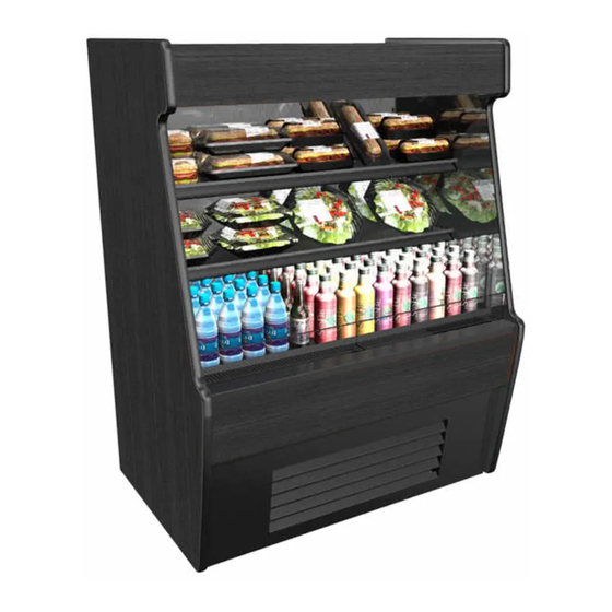
MOBILE REFRIGERATED SELF-SERVICE MERCHANDISER
> ROLL-DOWN SECURITY DOORS ARE OPTIONAL ON ALL UNITS
> BREEZE-E WITH ENERGYWISE IS STANDARD ON ALL UNITS
> REAR PLENUM DOORS ARE OPTIONAL ON ALL UNITS
Model CO37R Shown With Optional Roll-Down
Security Door (Similar Design to Models
CO35R, CO45R and CO47R)
MODEL CO35R.........36 1/4"L* x 33 1/4"D x 61 1/4"H^
MODEL CO45R.........47 1/4"L* x 33 1/4"D x 61 1/4"H^
MODEL CO55R.........59 1/4"L* x 33 1/4"D x 61 1/4"H^
MODEL CO65R.........71 1/4"L* x 33 1/4"D x 61 1/4"H^
*Includes End Panels.
I:\Oper Manuals\Oasis\CO35R_CO37R_CO45R_CO47R_CO55R_CO57R_CO65R_CO67R_20-13644.pub
READ AND SAVE THESE INSTRUCTIONS
INSTALLATION & OPERATING
MANUAL - SCC P/N 20-13644
^With Levelers Extended 1 1/4" From Base Frame
888 E. Porter Road · Muskegon, MI 49441 Phone: 231.798.8888 Fax: 231.798.4960 www.structuralconcepts.com
Model CO57R Shown With Optional Roll-Down
Security Door (Similar Design to Models
CO55R, CO65R and CO67R)
MODEL CO37R.........36 1/4"L* x 33 1/4"D x 81"H^
|||||||||
MODEL CO47R.........47 1/4"L* x 33 1/4"D x 81"H^
|||||||||
MODEL CO57R.........59 1/4"L* x 33 1/4"D x 81"H^
|||||||||
MODEL CO67R.........71 1/4"L* x 33 1/4"D x 81"H^
Important!
If Adjoining Cases,
See Synchronous
Defrost Connection
Instructions On Page
7 AND Adjoinment
Instructions on Page
8 In This Manual.
Revision J: 11/13/2017
Advertisement
Table of Contents
Troubleshooting

Related Manuals for Structural Concepts Oasis Mobile Series


Summary of Contents for Structural Concepts Oasis Mobile Series
- Page 1 READ AND SAVE THESE INSTRUCTIONS Important! INSTALLATION & OPERATING If Adjoining Cases, MANUAL - SCC P/N 20-13644 See Synchronous M O B I L E S E R I E S Defrost Connection Instructions On Page 7 AND Adjoinment MOBILE REFRIGERATED SELF-SERVICE MERCHANDISER Instructions on Page >...
-
Page 2: Table Of Contents
TABLE OF CONTENTS OVERVIEW / TYPE 1 VS. TYPE 2 CONDITIONS / COMPLIANCE / WARNINGS / PRECAUTIONS / WIRING .……….………………………………………………………………………………….…….. CASE REMOVAL FROM SKID (LEVELERS OR CASTERS) …….……………...………………..……… INSTALLATION: MERCHANDISER SET-UP, ELECTRICAL SET-UP, OPT. REMOTE SYSTEM ...… INSTALLATION, CONTINUED: SYNCHRONOUS DEFROST CONNECTION (OPTIONAL) …………. INSTALLATION, CONTINUED: CAULKING &... -
Page 3: Wiring
If unsure if your unit is Type I or II, see tag next to serial label. See SERIAL LABEL LOCATION & These Structural Concepts merchandisers are INFORMATION LISTED / TECH INFO & SERVICE designed to merchandise packaged products at section in this manual for sample serial labels. -
Page 4: Wiring
OVERVIEW / CONDITIONS / COMPLIANCE / WARNINGS / PRECAUTIONS / WIRING - PAGE 2 of 2 PRECAUTIONS WIRING DIAGRAM This sheet contains important precautions to prevent Each case has its own wiring diagram folded and in its damage to unit or merchandise. own packet. -
Page 5: Case Removal From Skid (Levelers Or Casters)
CASE REMOVAL FROM SKID (LEVELERS OR CASTERS) 1. Removing Case Shipping Brackets That Are Attached To Skid Remove screws holding Case Shipping Brackets to skid. Remove Case Shipping Brackets from Skid. See illustrations below. Note: Shipping Brackets will vary in size, shape, material and location depending upon case type and model. -
Page 6: Installation: Merchandiser Set-Up, Electrical Set-Up, Opt. Remote System
INSTALLATION: MERCHANDISER SET-UP, ELECTRICAL SET-UP, OPTIONAL REMOTE SYSTEM 1. Merchandiser Set-Up Hot Gas Electrical Leads Condensate Pan (If No Power Cord) Remove the rear lower grille. Ensure that the manufacturer provided hot gas evaporator pan is installed under the condensate drain. -
Page 7: Installation, Continued: Synchronous Defrost Connection (Optional)
INSTALLATION, CONTINUED: SYNCHRONOUS DEFROST CONNECTION (OPTIONAL) 4. Synchronous Defrost Connection (Optional) Adjoined cases MUST HAVE its synchronous defrost plugs connected. See wiring diagram accompanying case. Attention! Sample Adjoined cases have Synchronous Defrost Plug (Typ.) synchronous defrosts. Synchronous Defrost ... -
Page 8: Installation, Continued: Caulking & Bolting Adjoined Units
INSTALLATION, CONTINUED: SILICONE & BUTYL APPLICATION / BOLTING ADJOINED UNITS #2 hole is accessible near rear plenum. 5. Overview / Silicone and Butyl Application #3, 4 & 9 holes are accessible after removing decking. Sealant Overview: #5-6 holes are accessible after removing front panel. ... -
Page 9: Installation, Continued: Acrylic Divider Installation (Optional)
INSTALLATION, CONTINUED: ACRYLIC DIVIDER INSTALLATION (OPTIONAL) 7. Optional: Acrylic Divider Installation (Self-Contained Cases Only) The Acrylic Divider Kit contains the Acrylic piece, 1/4-20 screws and washers. The Acrylic Divider is to be installed on the Left Case (when facing cases). When properly installed, it will be flush with inside edge of left Case tab, to allow for seamless adjoining of Cases. -
Page 10: Main Power Switch - Start-Up / Temperature Controller / Light Switch
MAIN POWER SWITCH - START-UP / TEMPERATURE CONTROLLER / LIGHT SWITCH 1. Main Power Switch - Start-Up 3. Light Switch At Header, Upper-Left Remove the front grille simply by lifting up and Whether fluorescent or LED lights are used on off (no screw removal required). -
Page 11: Optional Roll Down Security Door (See Next Page For Extended Door)
OPTIONAL ROLL DOWN SECURITY DOOR (SEE NEXT PAGE FOR EXTENDED DOOR) Roll Down Security Door (Optional): Shown Retracted Optional roll down security door has two handles for grasping, lowering and raising. After door is lowered, key may be turned clockwise to lock latch into strike bracket. ... -
Page 12: Optional Roll Down Security Door (See Previous Page For Retracted Door)
OPTIONAL ROLL DOWN SECURITY DOOR (SEE PREVIOUS PAGE FOR RETRACTED DOOR) Roll Down Security Door (Optional): Shown Extended Optional roll down security door has two handles for grasping, lowering and raising. After door is lowered, key may be turned clockwise to lock latch into strike bracket. -
Page 13: Stiffener (For Optional Roll Down Security Door) & Stiffener Brackets
STIFFENER (FOR OPTIONAL ROLL DOWN SECURITY DOOR) & STIFFENER BRACKETS 1. Stiffener (For Optional Roll Down Security Stiffener prong is to be held in place by bracket Door) slots (at lower section of case). See illustration #2, below-left, for view of stiffener ... -
Page 14: Maintenance Fundamentals: Light Fixtures / Caster Locks
Removal of lamp: If case is provided with LED lights, they will rarely require change-out. Contact Structural Concepts’ Technical Service Light Fixture Light Socket Department for replacement parts (see the Technical Service section of operating manual). Replacement of lamp: ... -
Page 15: Maintenance Fundamentals: Honeycomb Air Diffusers
MAINTENANCE FUNDAMENTALS: HONEYCOMB AIR DIFFUSERS Preventive maintenance should be performed Honeycomb every 30 days unless conditions warrant a more frequent replacement cycle. 1. Honeycomb Air Diffuser Removal Honeycomb is located in discharge air duct. A. Wedge a non-metallic device of suitable strength (such as a ballpoint pen) between the honeycomb and the end panel. -
Page 16: Maintenance Fundamentals: Shelf Assembly / Shelves / Light Fixture
MAINTENANCE FUNDAMENTALS: SHELF ASSEMBLY / SHELVES / LIGHT FIXTURE 1. Shelf Assembly Removal Shelves can be removed for maintenance, cleaning or adjustments Slide shelf back about 1/8 inch and rotate front Plug up while lifting shelf assembly. For lighted shelving, unplug the light cord. -
Page 17: Maintenance Fundamentals: Rear Doors (Rear Doors)
MAINTENANCE FUNDAMENTALS: REAR DOORS (OPTIONAL) Rear Doors (Optional) Rear doors are hinged with handles to allow access to case from rear. Handles and strike plates allow doors to securely latch. Illustration shown reflects model CO47R. Your rear door size may vary. Model CO47R is Shown Above. -
Page 18: Maintenance Fundamentals: Ballast Access
MAINTENANCE FUNDAMENTALS: BALLAST ACCESS Ballast Access Assembly or disassembly and servicing is to be accomplished by a licensed electrical contractor. Remove rear grille by lifting up and off. Ballast are mounted inside the electrical box. Illustrations shown reflect models CO37R and CO67R. Your model may slightly vary. Ballasts (In Electrical Box) Rear View of Model CO37R... -
Page 19: Evaporator Coil Fans Access
EVAPORATOR COIL FANS ACCESS Evaporator Coil Fans Access Remove all product. Remove display steps (if any). Remove deck pan for coil fans access. Caution! Turn off main power before accessing the evaporator coil / deck pan area. Rotating blades can cause severe injury! Air Return Grilles... -
Page 20: Condenser Package Layout: Models Co35R And Co37R Only
CONDENSER PACKAGE LAYOUT: MODELS CO35R AND CO37R ONLY Typical Configurations, Continued Note: Unit shown below is for models CO35R & CO37R only. Your condenser package layout may vary. Caution: Only certified refrigeration/electrical engineers or contractors are to access condenser unit. ... -
Page 21: Condenser Package Layout: Models Co45R, Co47R, Co55R & Co57R Only
CONDENSER PACKAGE LAYOUT: MODELS CO45R, CO47R, CO55R & CO57R ONLY Typical Configurations, Continued Note: Unit shown below is for Model CO45R, CO47R, CO55R & CO57R only. Your condenser package layout may vary. Caution: Only certified refrigeration/electrical engineers or contractors are to access condenser unit. ... -
Page 22: Condenser Package Layout: Model Co65R And Co67R Only
CONDENSER PACKAGE LAYOUT: MODELS CO65R AND CO67R ONLY Typical Configurations, Continued Note: Unit shown below is for Model CO65R and CO67R only. Your model’s condenser package layout may vary. Caution: Only certified refrigeration/electrical engineers or contractors are to access condenser unit. ... -
Page 23: Serial Label & Location / Technical Information / Additional Information
For additional technical information and service, see the TECHNICAL SERVICE page in this manual for instructions on contacting Structural Concepts’ Technical Service Department. See images below for samples of both refrigerated and non-refrigerated serial labels. -
Page 24: Cleaning Schedule (Performed By Store Personnel & Trained Service Providers)
CLEANING SCHEDULE (PERFORMED BY STORE PERSONNEL & TRAINED SERVICE PROVIDERS) Cleaning W* M* Task Clean Case Acrylic must be cleaned with a mild soap and water solution and a Exterior soft cloth (Never use a household cleaner on acrylic). Clean Case Shelves and decks can be cleaned with a warm soap and water so- Interior lution. -
Page 25: Preventive Maintenance (To Be Performed By Trained Service Providers)
PREVENTIVE MAINTENANCE (TO BE PERFORMED BY TRAINED SERVICE PROVIDER) - Page 1 of 2 Preventive Freq. Instructions Maintenance Case Monthly Condensing Coil: To remove rear grille, lift slots up and off hooks (no screw removal required. Exterior Use air pressure or industrial strength vacuum; clean dust and dirt that may collect on the Condenser Coil. -
Page 26: Preventive Maintenance (To Be Performed By Trained Service Providers)
PREVENTIVE MAINTENANCE (TO BE PERFORMED BY TRAINED SERVICE PROVIDER) - Page 2 of 2 WARNING! TURN OFF CASE BEFORE PERFORMING PREVENTIVE MAINTENANCE! Preventive Frequency Instructions Maintenance Case Exterior Quarterly Compressor Area: Disconnect power from case before cleaning condenser coil! Slide/Roll out from under case. -
Page 27: Troubleshooting (To Be Performed By Store Personnel)
TROUBLESHOOTING (TO BE PERFORMED BY STORE PERSONNEL) Condition Troubleshooting Product is Drying Out Check the relative humidity in the store. Water Is On The Floor Call service provider. Fan Emits Excessive Noise Call service provider. Case Lights Are Not Check that light switch is in the on position. Working Check that ALL of the light cords and plugs are properly connected. -
Page 28: Troubleshooting (To Be Performed By Trained Service Providers Only) - Page 1 Of 3
TROUBLESHOOTING (TO BE PERFORMED BY TRAINED SERVICE PROVIDERS ONLY) - PAGE 1 of 3 Condition Troubleshooting Case Not Lining See Installation Section for instructions on properly aligning case (alongside other cases) and adjusting levelers. Water Is On Floor Caution! Water on flooring can cause much damage! Until cause is determined (and repaired), follow these procedures: ... - Page 29 TROUBLESHOOTING (TO BE PERFORMED BY TRAINED SERVICE PROVIDERS ONLY) - PAGE 2 of 3 Condition Troubleshooting Fan Emits Excessive Check that the case is aligned, level and plumb. Noise Check evaporator fan for cleanliness. Unplug/power off fan motors. Check motor shaft for bearing wear. Check that fan motors are securely mounted in brackets.
- Page 30 TROUBLESHOOTING (TO BE PERFORMED BY TRAINED SERVICE PROVIDERS ONLY) - PAGE 3 of 3 Condition Troubleshooting Case Lights Are Not Check that light switch is in the on position. Light switch is at case front. Remove Working front panel (no screw removal required) to access. Check that ALL of the light cords and plugs are properly connected.
-
Page 31: Carel® Temperature Controller Information
Read And Save These Instructions - Page 1 of 3 Integrated Electronic Microprocessor Controller Programming The Instrument ▲ mute To Modify The Setpoint ▼ Press and hold the “SET” key for at least 1 second. 2. Use arrow keys ▲ ▼ on temperature ▲... - Page 32 Read And Save These Instructions - Page 2 of 3 Integrated Electronic Microprocessor Controller User Interface - Display Summary Table of Alarm and Signals: Display, Buzzer and Relay reset alarms w/manual reset / reset HACCP alarms / reset temp. monitoring...
- Page 33 Read And Save These Instructions - Page 3 of 3 Integrated Electronic Microprocessor Controller Summary Table of Operating Parameters CODE PARAMETER UOM* TYPE MINIMUM MAXIMUM DEFAULT Select Celsius (°C) or Fahrenheit (°F) flag Calibration of probe 1 °C/°F Calibration of probe 2 °C/°F For Case Specific...
-
Page 34: Technical Service Contact Information & Warranty Information
LIMITED WARRANTY All sales by Structural Concepts Corporation (SCC) are subject to the following limited warranty. “Goods” refers to the product or products being sold by SCC. Warranty Scope: Warranty is for equipment sold in the United States, Canada, Mexico and Puerto Rico. Equipment sold elsewhere may carry modified warranty.
Need help?
Do you have a question about the Oasis Mobile Series and is the answer not in the manual?
Questions and answers