
Subscribe to Our Youtube Channel
Related Manuals for Ametek mocon AQUATRAN 3/38


Summary of Contents for Ametek mocon AQUATRAN 3/38
- Page 1 AQUATRAN ® 3/38 Operator’s Manual Revision G Lauper Instruments AG Gas-Detection Irisweg 16B CH-3280 Murten Tel. +41 26 672 30 50 info@lauper-instruments.ch www.lauper-instruments.ch Part Number 143-216...
- Page 2 Trademarks & Patents MOCON and AQUATRAN are registered trademarks of MOCON, Inc. For information on applicable patents see: https://www.ametekmocon.com/aboutus/legal/intellectualproperty Copyright© 2021 MOCON, Inc. All rights reserved.
- Page 3 AQUATRAN 3/38 Operator’s Manual About This Manual About This Manual This manual explains how to set up and use the AQUATRAN 3/38 Water Vapor Transmission Rate System. This manual is designed for viewing electronically. Most references to other sections or chapters in this document are hyperlinks which can be used to navigate to the referenced section.
-
Page 4: Safety Information
Safety Information AQUATRAN 3/38 Operator’s Manual Safety Information Be sure to read and understand this section and all other applicable chapters of the Operator's Manual and all on-product safety signs before setting up, operating, and maintaining this analyzer. Safety signs appear in this manual and on the analyzer. All safety signs are identified by the words WARNING and CAUTION. -
Page 5: Table Of Contents
AQUATRAN 3/38 Operator’s Manual Table of Contents Table of Contents About This Manual ............................iii Safety Information ............................iv Chapter 1: Introduction..........................1-1 Features ............................... 1-2 Permeation Test Overview ........................1-3 Individual Zero Phase ........................1-3 Conditioning the Sample ........................ 1-3 ReZero State .......................... - Page 6 Table of Contents AQUATRAN 3/38 Operator’s Manual Chapter 6: Testing Film Samples ......................6-1 Testing Suggestions ..........................6-1 Preparing for a Film Test ........................6-2 Sample Size ............................6-2 Special Cartridge for Thick Samples ....................6-2 Using Masks ............................6-2 Orienting the Sample ...........................
- Page 7 AQUATRAN 3/38 Operator’s Manual Table of Contents How the Water Vapor Sensor Works ....................D-1 Water Vapor Sensor Calibration Theory ....................D-1 Barrier Temperature ........................D-2 Test Gas Driving Force ........................D-3 Barometric Pressure ........................D-3 Relative Humidity .......................... D-3 How a Humidified Test Gas is Generated....................
- Page 8 Table of Contents AQUATRAN 3/38 Operator’s Manual Figures Figure 1-1: AQUATRAN 3/38 System ....................... 1-1 Figure 1-2: The AQUATRAN 3/38 - 100% RH Test Cell ................1-5 Figure 2-1: Front Panel Parts and Controls ....................2-2 Figure 2-2: Front Panel Parts and Controls ....................2-4 Figure 2-3: Back Panel Parts and Controls ....................
-
Page 9: Chapter 1: Introduction
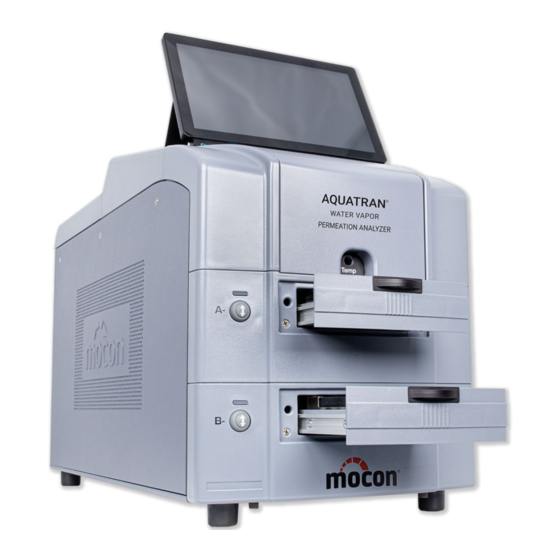
AQUATRAN 3/38 Operator’s Manual Introduction Chapter 1: Introduction This chapter provides a brief overview of the AQUATRAN 3/38 Water Vapor Transmission Rate System. Read this chapter to get an overview of: The features of the AQUATRAN 3/38 system • • A summary of basic steps in a permeation test •... -
Page 10: Features
Introduction AQUATRAN 3/38 Operator’s Manual Features The following features of the AQUATRAN 3/38 Water Vapor Transmission Rate System make it very versatile and easy to use: Fully automatic (Hands Off) testing. • Pneumatically clamped Test Cartridges. • Removable Dual-Film Test Cartridges for faster film mounting. •... -
Page 11: Permeation Test Overview
AQUATRAN 3/38 Operator’s Manual Introduction Permeation Test Overview A “Permeation Test” consists of up to two phases that are performed using a Test Cell. The “Cell” contains the film sample. The Test Phase (always present) is used to measure the transmission rate of the test sample. -
Page 12: Report Generation
Introduction AQUATRAN 3/38 Operator’s Manual At some point sufficient measurements will have been made to accurately determine the transmission rate of the samples. A Permeation Test can be terminated manually by the user, after a fixed number of test cycles or using an automatic convergence process. When testing is complete, the cell is removed from the test sequence and no further transmission rate examination of that sample is performed. -
Page 13: Measuring Water Vapor Transmission Rate
AQUATRAN 3/38 Operator’s Manual Introduction Measuring Water Vapor Transmission Rate To make an accurate transmission rate measurement a known concentration Test Gas (usually 100% Water vapor) is applied to one side of the barrier material to be tested and the other side is swept with a water vapor free Carrier Gas (nitrogen). -
Page 14: Testing Samples
Introduction AQUATRAN 3/38 Operator’s Manual Testing Samples The AQUATRAN 3/38 is designed measure the Water Vapor Transmission Rate of film samples. The AQUATRAN 3/38 provides no capability for testing packages. To test a film sample, it is prepared and mounted in a Test Cartridge. Both positions in the Test Cartridge (referred to as the top and bottom) must contain a film or foil. -
Page 15: Chapter 2: Setting Up
AQUATRAN 3/38 Operator’s Manual Setting Up Chapter 2: Setting Up This chapter provides information on how to set up an AQUATRAN 3/38 and prepare it for use. Read this chapter to learn about: Unpacking the System • • Preparing for System Installation •... -
Page 16: Front Panel Parts And Controls
Setting Up AQUATRAN 3/38 Operator’s Manual Front Panel Parts and Controls The names and locations of the parts and controls located on the front of the instrument are shown in Figure 2-1, Figure 2-2 and Table 2.1. Figure 2-1: Front Panel Parts and Controls Revision G MOCON, Inc. - Page 17 AQUATRAN 3/38 Operator’s Manual Setting Up MOCON, Inc. Revision G...
-
Page 18: Figure 2-2: Front Panel Parts And Controls
Setting Up AQUATRAN 3/38 Operator’s Manual Figure 2-2: Front Panel Parts and Controls Item Name Description Cartridge B Load/Unload button This button is used to Load and Unload the Test Cartridge Cartridge B Status Indicator This indicator is used to show the Status of Cartridge B Cartridge A Load/Unload button This button is used to Load and Unload the Test Cartridge Cartridge A Status Indicator... -
Page 19: Back Panel Parts And Controls
AQUATRAN 3/38 Operator’s Manual Setting Up Back Panel Parts and Controls The names and locations of the parts and controls located on the back of the instrument are shown in Figure 2-3 and Table 2.2. Figure 2-3: Back Panel Parts and Controls MOCON, Inc. -
Page 20: Table 2-2: Back Panel Parts And Controls
Setting Up AQUATRAN 3/38 Operator’s Manual Item Name Description Power In The connector the power cord attaches to. Fuse Holder The fuse holder contains the fuses used to protect the instrument. The switch that is used to turn the instrument on and off. l is ON Power Switch О... -
Page 21: Carrier Gas (Nitrogen)
AQUATRAN 3/38 Operator’s Manual Setting Up Carrier Gas (Nitrogen) The AQUATRAN 3/38 requires a Carrier Gas that is 99.7% nitrogen. A standard T size cylinder will typically provide sufficient gas to operate a single instrument for several weeks. Gas Distribution System Each instrument ships with a local regulator/isolation device (called a Regulator Tee) that can be used to connect the instrument to a common Carrier Gas distribution system. -
Page 22: Connecting The Gas Lines
Setting Up AQUATRAN 3/38 Operator’s Manual Connecting the Gas Lines The AQUATRAN 3/38 has a gas inlet for connection of the Carrier Gas (nitrogen) supply. This compression fitting is intended for use with 1/8” copper tubing. Refer to Figure 2-3 and Figure 2-4 for the location of the fitting and an example of plumbing system diagram. -
Page 23: Setting The Gas Supply Pressure
AQUATRAN 3/38 Operator’s Manual Setting Up Connect the inlet fitting on the regulator tee to the output fitting on the Desiccant Tower using the tubing a nut and a ferrule. Make sure the tube is inserted all the way into the fitting on the Desiccant Tower before tightening the knurled nut. - Page 24 Setting Up AQUATRAN 3/38 Operator’s Manual Before the system can be used any air trapped in the gas lines and instrument must be purged out. After purging the carrier gas supply system, the instrument must be outgassed. After the initial purge residual water vapor may still be present in the seals and void spaces within in the instrument.
-
Page 25: Chapter 3: Preparing For A Test
AQUATRAN 3/38 Operator’s Manual Preparing for a Test Chapter 3: Preparing for a Test This chapter provides information on how to prepare for a permeation test. Read this chapter to learn about: Testing Basics • • How Barrier Properties Affect Testing •... -
Page 26: Testing Moisture Sensitive Barriers
Preparing for a Test AQUATRAN 3/38 Operator’s Manual Testing Moisture Sensitive Barriers With some materials such as nylon, cellophane and ethyl vinyl alcohol, variations in the amount of water vapor absorbed from the test gas will significantly affect the Water Vapor Transmission Rate. Some hydroscopic materials expand or swell when water is absorbed into the polymer or fiber structure. -
Page 27: The Sample Conditioning Time
AQUATRAN 3/38 Operator’s Manual Preparing for a Test The Sample Conditioning Time When you condition a sample in the test cell, carrier gas and test gases are routed to the test cell as they are during testing. However, the carrier gas is not routed to the water vapor sensor. This conditioning period allows a sample barrier to acclimate to the conditions within the test cell. -
Page 28: Determining When To Stop A Test
Preparing for a Test AQUATRAN 3/38 Operator’s Manual Determining When to Stop a Test The setting used for the “Test Mode” parameter determines how and when a transmission rate test is stopped (Test Completion). Four different methods of stopping a transmission rate test are provided. The four methods are: “Continuous”, “Standard”, “Convergence By Cycles”... -
Page 29: Chapter 4: Using The Instrument Software
AQUATRAN 3/38 Operator’s Manual Using the Instrument Software Chapter 4: Using the Instrument Software This chapter provides an overview of the software system used to operate the AQUATRAN 3/38. Detailed information on how to use the instrument software can be found in the Instrument Help System. Read this chapter to learn about: •... -
Page 30: Instrument Software Structure And Organization
Using the Instrument Software AQUATRAN 3/38 Operator’s Manual Instrument Software Structure and Organization All the User Interface and Instrument Control functions of your permeation system are accessed through the Instrument Software. The User Interface consists of a Title bar, an Icon bar, and the Workspace The “Title”... -
Page 31: Chapter 5: Permeant Sensor Calibration
AQUATRAN 3/38 Operator’s Manual Calibrating the Permeant Sensor Chapter 5: Permeant Sensor Calibration You will need to calibrate the system to ensure accuracy in determining water vapor transmission rates. Calibration also ensures proper automatic compensation in the transmission rates when environmental and other factors cause the system to drift. - Page 32 Calibrating the Permeant Sensor AQUATRAN 3/38 Operator’s Manual Calibration of the permeant (water vapor) sensor is a two-step process. First, a film sample with a known transmission rate must be tested. Refer to the “Permeant Sensor Calibration Test Setup” in this chapter for information on setting up a film test.
-
Page 33: Permeant Sensor Calibration Test Setup
AQUATRAN 3/38 Operator’s Manual Calibrating the Permeant Sensor Permeant Sensor Calibration Test Setup To calibrate an instrument to a standard reference film or a certified film use the following procedure: MOCON has available Certified NIST Films that cover the usual testing range. Call MOCON NOTE: in the USA for more information at (763) 493-6370. - Page 34 Calibrating the Permeant Sensor AQUATRAN 3/38 Operator’s Manual Verify the following Cell Level parameters have been correctly assigned: Area/Cell: Verify the area is set correctly if not using a Certified film. Package/Film selection: Verify that Package is selected if using a Certified film. If using another film, set the Package/Film buttons to the appropriate selection for the method used to establish the reference transmission rate.
-
Page 35: Chapter 6: Testing Film Samples
AQUATRAN 3/38 Operator’s Manual Testing Film Samples Chapter 6: Testing Film Samples This chapter contains information on how to test flat film samples. Suggestions on how to maximize the accuracy of your results and procedures describing how to perform the test are discussed. Read this chapter to learn about: •... -
Page 36: Preparing For A Film Test
Testing Film Samples AQUATRAN 3/38 Operator’s Manual Preparing for a Film Test Before a test can be conducted there are a number of tasks that must be performed: The samples to be tested must be prepared. The samples must be mounted in a Test Cartridge and Loaded into the instrument. - Page 37 AQUATRAN 3/38 Operator’s Manual Testing Film Samples If your sample is thin (less than 5 mils), you need only mask one side. Mount the sample in the test cell with the film side facing up. If your sample is thicker than 5 mils, mask both sides. Be sure the mask apertures are accurately aligned and the edges around the foil aperture are tight against the film.
-
Page 38: Orienting The Sample
Testing Film Samples AQUATRAN 3/38 Operator’s Manual Orienting the Sample When mounting test samples, orientation can be important. Edge leakage or oxidation on some materials can affect the test result. It is important to place the “barrier side towards the carrier”. Follow the guidelines below to minimize edge leakage and oxidation effects. -
Page 39: Using A Generated Rh Test Gas
AQUATRAN 3/38 Operator’s Manual Testing Film Samples Using a Generated RH Test Gas The AQUATRAN 3/38 has the capability of generating a controlled RH from 5 to 90% for the Test Gas. A Generated RH Test Gas is created by moving pressurized gas through a humidifier filled with HPLC-grade water and mixing the wet gas with a dry gas in the appropriate ratios. -
Page 40: Humidifier Ports And Controls
Testing Film Samples AQUATRAN 3/38 Operator’s Manual Close the Fill Valve and remove the syringe. Start a ReZero examination using the GoTo control. Humidifier Ports and Controls The ports and controls used to fill the Water Reservoir used for Generated RH testing are illustrated in the figure and table below. -
Page 41: Mounting Samples In The Test Cartridge
AQUATRAN 3/38 Operator’s Manual Testing Film Samples Mounting Samples in the Test Cartridge Follow the instructions below to mount film samples in the Test Cartridge: Note: Both positions (Top & Bottom) must contain a film or foil. If both positions are not required, a Foil may be mounted in the unused position. -
Page 42: Figure 6-2: Mounting A Film Sample (Bottom Position)
Testing Film Samples AQUATRAN 3/38 Operator’s Manual Figure 6-2: Mounting a Film Sample (Bottom Position) Revision G MOCON, Inc. -
Page 43: Mounting A Sample In The Top Test Cartridge Position
AQUATRAN 3/38 Operator’s Manual Testing Film Samples Mounting a Sample in the top Test Cartridge position Place the partially assembled Test Cartridge on a flat surface with the top mounting surface Place the film on the greased sealing surface, remove any wrinkles as necessary. Verify the inner and outer O-Rings are properly seated in the top Test Gas Plate. -
Page 44: Figure 6-4: Loading The Test Cartridge
Testing Film Samples AQUATRAN 3/38 Operator’s Manual Open the Cartridge Tray completely by gently pulling straight back from the front panel. Grasp the Test Cartridge by the front and back edges and lift straight up. To Load the Test Cartridge into the instrument, follow the instructions below (refer to Figure 6-4 and 6-5): Grasp the Test Cartridge by the front and back edges and lower it straight down. -
Page 45: Setting Up And Starting A Film Test
AQUATRAN 3/38 Operator’s Manual Testing Film Samples Figure 6-5: Press Load/Unload Button While Holding the Tray Setting Up and Starting a Film Test After the samples are loaded and the instrument is ready there are a number of test parameters that must be set. -
Page 46: Monitoring And Controlling A Film Test
Testing Film Samples AQUATRAN 3/38 Operator’s Manual A permeation test can be setup using a “Saved Test Method” by selecting the “Methods” control displayed at the bottom of the Advanced Test Method screens. For more information on setting up and starting a test see the Instrument Help system. Monitoring and Controlling a Film Test The status of an active test can be monitored and controlled using the “Home”, “Cell Status”... -
Page 47: Chapter 7: Maintenance
AQUATRAN 3/38 Operator’s Manual Maintenance Chapter 7: Maintenance This contains information on how to clean and maintain the AQUATRAN 3/38. Read this chapter to learn about: Cleaning the Instrument • • Cleaning the Test Cell • Cleaning the Air Filters •... -
Page 48: Cleaning The Air Filters
Maintenance AQUATRAN 3/38 Operator’s Manual Cleaning the Air Filters Periodically the air filter on the back of the instrument should be removed and cleaned. The recommended interval is twice a year (or whenever there is a significant buildup of dust). If the filter is not cleaned on a regular basis air will not circulate properly through the cooling system. -
Page 49: Cleaning The Test Cells
AQUATRAN 3/38 Operator’s Manual Maintenance To remove the cooling system air filter, remove the two nuts shown in Figure 7-1 above. Cleaning the Test Cells Periodically the test cells should be cleaned to remove any excess buildup of grease. Alcohol can be used to remove any residue from the High Vacuum grease. -
Page 50: Test Cartridge Components And Part Numbers
Maintenance AQUATRAN 3/38 Operator’s Manual Test Cartridge Components and Part Numbers The parts of the test cartridge are shown in Figure 7-2 below. Refer to Table 7.1 for the associated part numbers and the quantity used. To order replacement parts contact MOCON in the USA at (763) 493-6370. Figure 7-2: Test Cartridge Components Revision G MOCON, Inc. -
Page 51: Table 7-1: Test Cartridge Part Numbers
AQUATRAN 3/38 Operator’s Manual Maintenance Item Quantity Part Number Description 031-070 Barb, Hose, 10-32, Nickel-Plated Brass 033-613 O-Ring, 0.087 ID X 0.040 CS, Buna N, 70 Durometer 050-112 O-Ring, 0.145 ID X 0.070 CS, Viton 052-185 O-Ring, 3.661 ID X 0.050 CS, Buna-N 054-070 Cell, Test, Bottom, HT 054-071... -
Page 52: Changing The Desiccant
Maintenance AQUATRAN 3/38 Operator’s Manual Changing the Desiccant The desiccant chamber is located in-line between the regulator tee assembly and the nitrogen tank. Change the desiccant whenever the blue indicator starts to turn pink. Refer to Figure 7-3 and follow the directions below to change the desiccant: Warning! The desiccant chamber contains high pressure and will cause personal injury if... -
Page 53: Figure 7-3: The Desiccant Chamber
AQUATRAN 3/38 Operator’s Manual Maintenance Caution: To eliminate the possibility of gross leaks, you should make sure the copper tubing is fully inserted into the desiccant chamber fittings and that the o-ring and ferrule are installed and positioned correctly (see Figure 7-3). Figure 7-3: The Desiccant Chamber MOCON, Inc. -
Page 54: System Standby
Maintenance AQUATRAN 3/38 Operator’s Manual System Standby When a test series is complete, the instrument sets the sensor to the Bypass state. In this position the sensor is isolated and protected from inadvertent exposure to large amounts of water vapor. If no testing will be performed for an extended period of time (overnight or weekend) leave a film mounted and clamped in the test cells. -
Page 55: Chapter 8: Troubleshooting
AQUATRAN 3/38 Operator’s Manual Trouble Shooting Chapter 8: Troubleshooting This chapter contains information to assist you in solving problems that may occur during the operation of the instrument. Read this chapter to learn about: • Error Messages and Warnings • Solving Operational Problems Sensor Over-Range Recovery •... -
Page 56: Recovering From A Sensor Over-Range Condition
Troubleshooting AQUATRAN 3/38 Operator’s Manual Recovering from a Sensor Over-Range Condition A severe over range condition will terminate the test sequence on both cells. If you see a red Cartridge Status indicator (on the front of the instrument), the test has failed due to a permeant sensor over-range condition. -
Page 57: Chapter 9 Specifications
AQUATRAN 3/38 Operator’s Manual Specifications Chapter 9 Specifications This chapter contains the specifications of the AQUATRAN 3/38. Read this chapter for details about: Physical specifications • • Environmental requirements Electrical requirements • • Gas Supply requirements Operational capabilities • Physical Specifications Height Width Depth... -
Page 58: Table 9-3: Electrical Specifications
Specifications AQUATRAN 3/38 Operator’s Manual Electrical Requirements Voltage 100 - 240 VAC 50/60 Hz Maximum Power Draw 700 VA Current Draw at 100 VAC 50 Hz 1.80 A nominal Current Draw at 120 VAC 60 Hz 1.50 A nominal Current Draw at 220 VAC 50 Hz 0.82 A nominal Current Draw at 240 VAC 50 Hz 0.75 A nominal... -
Page 59: Table 9-4: Gas Supply Specifications
AQUATRAN 3/38 Operator’s Manual Specifications Gas Supply Requirements Gas Composition Nitrogen (99.7% N or better) Supply Pressure, Nominal 29 PSI, (2.0 Bar), (200 kPa) Supply Pressure, Maximum 32 PSI, (2.2 Bar), (220 kPa) Carrier Gas Supply Pressure, Minimum 26 PSI, (1.8 Bar), (179 kPa) Flow Rate, Maximum 555 cc/minute (Test Active 100cc/min) Flow Rate, Minimum... -
Page 60: Transmission Rate Range And Repeatability Capabilities
Specifications AQUATRAN 3/38 Operator’s Manual Transmission Rate Range and Repeatability Capabilities Minimum Carrier Exam Calibration Testing Range Repeatability Flow Time Standard Required 2.5 to 100 gm/(m -day) Certified Film 0.161 to 6.45 gm/(100 -day) P/N 054-162 +/- 2.0% of Reading sccm minutes 0.0125 to 0.50 gm/(pkg-day) -
Page 61: Appendix A: Site Preparation Instructions
AQUATRAN 3/38 Operator’s Manual Site Preparation Instructions Appendix A: Site Preparation Instructions P/N 140-223 (See next page) MOCON, Inc. Revision G... - Page 62 Site Preparation Instructions AQUATRAN 3/38 Operator’s Manual P/N 140-223 Revision A 7500 Mendelssohn Avenue North Minneapolis, MN 55428 U.S.A. Telephone 763-493-6370 Web Site: www.ametekmocon.com SITE PREPARATION INSTRUCTIONS IMPORTANT! REQUIREMENTS FOR THE START-UP OF THE AQUATRAN 3/38 SYSTEM ® The following must be furnished by the customer before a new AQUATRAN 3/38 can be set up. If a MOCON technical representative will be setting up your system these items must be on site before we can arrange to visit your plant.
- Page 63 AQUATRAN 3/38 Operator’s Manual Site Preparation Instructions DISTILLED WATER - You should use HPLC grade water for relative humidity generation. Obtain this water through a local supplier. REGULATOR ASSEMBLY - If the customer chooses to purchase the optional regulator, then the gas cylinder is the only item that must be supplied by the customer.
- Page 64 The MOCON AQUATRAN 3/38 system will provide years of useful life provided these requirements are observed. Please contact MOCON in the USA at (763) 493-6370 with any questions regarding these Site Preparation Instructions.
-
Page 65: Appendix B: Spare Parts
AQUATRAN 3/38 Operator’s Manual Spare Parts Appendix B: Spare Parts The following is a list of the spare parts that are available for the AQUATRAN 3/38. To order, contact MOCON in the USA at (763) 493-6370. Part Unit of Description Quantity Number Measure... - Page 66 Spare Parts AQUATRAN 3/38 Operator’s Manual Part Unit of Description Quantity Number Measure 130-015 Mask, Alum Foil, 5 CM , 4 X 4, 0.994 Hole, No Mounting Holes 143-216 Manuscript, AQUATRAN, 3/38, On Flash Drive 210-017 Cord, Power, 125V, 18/3, SVT, IEC, Unshielded, 7 1/2 FT 310-027 Nut, 1/8 Tube, Brass 310-051...
-
Page 67: Appendix C: Warranty And Service Policies
AQUATRAN 3/38 Operator’s Manual Warranty and Service Policies Appendix C: Warranty and Service Policies Part Number: 032-846, Warranty Policy Part Number: 032-847, International Service Policy Part Number: 032-848, Domestic Service Policy (See next pages) MOCON, Inc. Revision G... - Page 68 Warranty and Service Policies AQUATRAN 3/38 Operator’s Manual Part Number 032-846 Revision G 7500 Mendelssohn Avenue North Minneapolis, MN 55428 USA Telephone 763-493-6370 Web Site: www.ametekmocon.com WARRANTY POLICY STATEMENT OF LIMITED WARRANTY MOCON, Inc. warrants that any part of any MOCON instrument or accessory ( “ I n s t r u m e n t ” ) which proves to be defective in material or workmanship during the warranty period will be repaired by MOCON "certified"...
- Page 69 AQUATRAN 3/38 Operator’s Manual Warranty and Service Policies Spare parts, repairs and accessories when purchased separately and not a part of a new instrument order. Ninety days from date of shipment from MOCON's factory. • This warranty covers normal use only. It does not cover damage that results from alteration, accident, misuse, abuse, neglect, or failure to follow assembly, installation, operational, or other MOCON instruction.
- Page 70 Warranty and Service Policies AQUATRAN 3/38 Operator’s Manual Part Number 032-847 Revision D 7500 Mendelssohn Avenue North Minneapolis, MN 55428 USA Telephone 763-493-6370 Web Site: www.ametekmocon.com INTERNATIONAL SERVICE POLICY MOCON offers a complete range of service options to purchasers of MOCON instrumentation and systems. ♦♦♦SERVICE PERFORMED WITHIN THE WARRANTY PERIOD♦♦♦...
- Page 71 AQUATRAN 3/38 Operator’s Manual Warranty and Service Policies Part Number 032-848 Revision G 7500 Mendelssohn Avenue North Minneapolis, MN 55428 USA Telephone 763-493-6370 Web Site: www.ametekmocon.com DOMESTIC SERVICE POLICY MOCON offers a complete range of service options to purchasers of MOCON instrumentation and systems. ♦♦♦SERVICE PERFORMED WITHIN THE WARRANTY PERIOD♦♦♦...
- Page 72 Warranty and Service Policies AQUATRAN 3/38 Operator’s Manual Invoices are due NET 30 days (with approved credit) and are billed and payable in U.S. dollars. • • All parts are shipped EXW MOCON factory Minneapolis, Minnesota; freight and Insurance will be billed separately. MOCON insures all shipments unless advised otherwise.
-
Page 73: Appendix D: Theory Of Operation
AQUATRAN 3/38 Operator’s Manual Theory of Operation Appendix D: Theory of Operation How the Water Vapor Transmission Rate is measured When a film is installed in a Test Cartridge, it is exposed to a continuous flow of dry nitrogen gas across the one side (the Carrier Gas side) and an RH on the other (the Test Gas side). -
Page 74: Barrier Temperature
Theory of Operation AQUATRAN 3/38 Operator’s Manual Room temperature and humidity are just two of many factors that can marginally affect test results. Consequently, a piece of film with a known WVTR will test higher or lower. Any reference film, whose WVTR has been established, may be used for calibration. A reference film at any arbitrarily constant test flow will produce an arbitrary constant amount of water vapor in the carrier gas. -
Page 75: Test Gas Driving Force
AQUATRAN 3/38 Operator’s Manual Theory of Operation Test Gas Driving Force The driving force of the test gas has a direct effect on the water vapor transmission rate. The driving force of the test gas is affected by the water vapor concentration (RH) of the test gas and the ambient Barometric pressure. -
Page 76: How A Humidified Test Gas Is Generated
Theory of Operation AQUATRAN 3/38 Operator’s Manual How a Humidified Test Gas is Generated A Humidified Test Gas is created by moving pressurized gas through a humidifier filled with HPLC-grade water and mixing the wet gas with a dry gas in the appropriate ratios. A mixing valve is used to “mix”... -
Page 77: Appendix E: Electrical And Plumbing Diagrams
AQUATRAN 3/38 Operator’s Manual Electrical and Plumbing Diagrams Appendix E: Electrical and Plumbing Diagrams Title Part Number Plumbing Diagram, AQUATRAN 3/38 051-953 Electrical Diagram, AQUATRAN 3/38 051-954 MOCON, Inc. Revision G... - Page 78 Electrical and Plumbing Diagrams AQUATRAN 3/38 Operator’s Manual Figure 9-1: Plumbing Diagram Page 1 Revision G MOCON, Inc.
- Page 79 AQUATRAN 3/38 Operator’s Manual Electrical and Plumbing Diagrams Figure 9-2: Plumbing Diagram Page 2 MOCON, Inc. Revision G...
- Page 80 Electrical and Plumbing Diagrams AQUATRAN 3/38 Operator’s Manual Figure 9-3: Electrical Diagram Page 1 Revision G MOCON, Inc.
- Page 81 AQUATRAN 3/38 Operator’s Manual Electrical and Plumbing Diagrams Figure 9-4: Electrical Diagram Page 2 MOCON, Inc. Revision G...
- Page 82 Electrical and Plumbing Diagrams AQUATRAN 3/38 Operator’s Manual Figure 9-5: Electrical Diagram Page 3 Revision G MOCON, Inc.
-
Page 83: Appendix F: Preparing Rh Calibration Standards
AQUATRAN 3/38 Operator’s Manual Preparing RH Calibration Standards Appendix F: Preparing RH Calibration Standards To calibrate or check the RH probes used in the AQUATRAN 3/38, requires RH reference values (or standards). A RH Calibration Standard consists of a saturated salt solution or molecular sieve in a “Calibration Flask”. -
Page 84: Preparing A High-Level Calibration Standard
Preparing RH Calibration Standards AQUATRAN 3/38 Operator’s Manual Preparing a High-Level Calibration Standard A High-Level RH Calibration standard can be prepared using a salt solution as follows: Chose the appropriate salt for the calibration standard. See “Choosing a Salt for a Calibration Standard”... -
Page 85: Appendix G: Compliance
AQUATRAN 3/38 Operator’s Manual Compliance Appendix G: Compliance MOCON, Inc. Revision G...
Need help?
Do you have a question about the mocon AQUATRAN 3/38 and is the answer not in the manual?
Questions and answers