Table of Contents
Advertisement
Quick Links
Advertisement
Table of Contents

Subscribe to Our Youtube Channel
Related Manuals for Ametek PMC-200


Summary of Contents for Ametek PMC-200
- Page 1 PMC-200 Hardware Manual P/N XXXXXXX...
-
Page 2: Table Of Contents
PMC-200 Hardware Manual P/N XXXXXX Safety Instructions and Symbols ......................4 Cleaning Instructions ..........................4 INTRODUCTION ..........................5 1.1. General ............................6 1.2. Hardware Circuitry ........................6 1.2.1. Potentiostatic mode ......................7 1.2.2. Galvanostatic mode ......................7 1.3. Software ............................7 1.4. - Page 3 4.6. Replacing the Backplane Module ..................48 4.7. Airflow considerations ......................56 SPECIFICATIONS AND PINOUTS ....................58 5.1. Electronic Specifications of the PMC-200 ................58 5.1.1. System Performance ....................... 58 5.1.2. Power Amplifier ........................ 58 5.1.3. Voltage Control ........................ 58 5.1.4.
-
Page 4: Safety Instructions And Symbols
PMC-200 Hardware Manual P/N XXXXXX Safety Instructions and Symbols This manual contains up to three levels of safety instructions that must be observed in order to avoid personal injury and/or damage to equipment or other property. These are: Safety Keywords:... -
Page 5: Introduction
FRA/PMC-500 FRA option for PMC-500, PMC-500/HI, or PMC-500/LO This manual covers models PMC-200; the term PMC-200 in the manual text represents a single module with two channels unless explicitly identified. It is controlled from any suitably equipped PC by a Universal Serial Bus (USB) interface using the VersaStudio electrochemistry software package. -
Page 6: General
An onboard microprocessor per channel to perform the experiment defined by the operating software. Onboard memory to store the programmed parameters and data point values. Each PMC-200 operates with VersaStudio in either the potentiostatic or galvanostatic mode, described below. PMC-200 Hardware Manual... -
Page 7: Potentiostatic Mode
PMC-200 Hardware Manual P/N XXXXXX 1.2.1. Potentiostatic mode In this mode, the PMC-200 controls the potential at the working-sense electrode with respect to the reference electrode (see Figure 2). The counter electrode is driven to the potential required (consistent with the + 10 V compliance of the control amplifier) to establish the desired working potential. -
Page 8: Polarity Convention
Windows 10 or 7 be used. 1.4. Polarity Convention The PMC-200 hardware follows the American polarity convention. (Positive current is cathodic; that is, a current is defined as positive if reduction is taking place at the working electrode. Negative current is anodic;... - Page 9 PMC-200 Hardware Manual P/N XXXXXX Chapter 5 gives the physical and electrical specifications of the PMC-200. As noted above, the PARSTAT MC is completely computer controlled; operation and experimental procedures are covered in the software section of this manual. PMC-200 Hardware Manual...
-
Page 10: Safety And Component Placement
Replacement fuses can be source from Ametek or locally. There are 2 fuses per PWR01 module. Contact Ametek for a power cord if changing service to a different country line voltage, so that the correct power cord is used per Table 1. -
Page 11: Component Placement
PMC-200 Hardware Manual P/N XXXXXX • has been subjected to severe transport stresses. The instrument should not be used until its safety has been verified by qualified service personnel. The PMC CHS08A chassis contains three different user-replaceable parts – Fan (PMC FAN01), Power Supply (PMC PWR01) and Backplane (PMC BPLN01). -
Page 12: Transient Sensitivity
PMC-200 Hardware Manual P/N XXXXXX 2.2.1. Transient Sensitivity Princeton Applied Research instruments are designed and constructed to ensure normal operation in the presence of moderate transient levels. Although these provisions are sufficient for operation in most places where the equipment is used, it is certainly possible for transient levels in particular environments to be so severe that they make reliable operation uncertain. -
Page 13: Parstat Mc (Pmc) Installation
There is a 4 million data point buffer per PMC-200 channel. Data collection is not affected by latency in display. The experiment continues to run and data files and display are populated as data transfer happens. -
Page 14: Front Panel
PMC-200 Hardware Manual P/N XXXXXX Figure 3. Rear panel of PARSTAT MC (PMC CHS08A Chassis) 3.2.1.1. INPUT POWER 100-240-Vac. See section 2.1.1 for details. 3.2.1.2. USB Attach the supplied USB cable to this connector and to the USB connector on the PC. You can connect to and disconnect from the PC without shutting down or restarting Windows or VersaStudio. -
Page 15: Equipment Installation
The cell cable is described in more detail below. 3.2.2.4. INDICATORS POWER: This indicator lights when the PMC-200 module is powered on. STATUS: Provides the status of each channel COMM: Indications communication between the channel and the computer OVERLOAD: This red LED indicates overloads that one of the measurement channels are overloaded 3.3. -
Page 16: Protective Earthing
CD into the CD-ROM drive, and select “Automatic” to install the driver. This driver should be located in the C:\Program Files\Princeton Applied Research\VersaStudio\ folder. 3.4.2. Connecting the Cell To connect the cell cable (part no. 1108584) to the PMC-200: PMC-200 Hardware Manual... - Page 17 Though not required, best practice recommends that you first power off the Chassis. Match and attach the D connector side of the Cell cable to the front of the PMC-200, and secure the screws on either side. After cell cable is connected to front panel, power the unit on and let it boot fully (approximately 1 min to boot up) before connecting a cell to the leads of the cell cable.
- Page 18 PMC-200 Hardware Manual P/N XXXXXX The following descriptions and figures explain how to connect a two-, three-, or four-terminal electrochemical cell to the terminals of the PMC-200 cell cable. a) Batteries, capacitors, resistors, fuel cells, and some sensors are generally connected using a two- terminal connection (Figure 7).
-
Page 19: Cell Cables And Compatibility
After all other connections to the PMC-200 are made an experiment can be set up and performed. 3.4.3. Cell Cables and Compatibility The cell cable for the PMC-200 uses a different connector than is used on the PMC-1000, PMC-2000A series. -
Page 20: Floating Operation
In floating mode, the internal ground of the PMC-200 (as well as the cell leads and external connections at the rear panel) is allowed to float with respect to earth ground which allows it to operate with these grounded cells. -
Page 21: Setting Operation Modes Of Float And Normal
PMC-200 Hardware Manual P/N XXXXXX 3.5.1. Setting Operation Modes of Float and Normal The PARSTAT MC control software, VersaStudio, provides an Options menu (Tools → Options…) where the mode can be changed to either “normal” or “floating” as shown below: Figure 10. -
Page 22: Replacing Modules Of The Parstat Mc Chassis
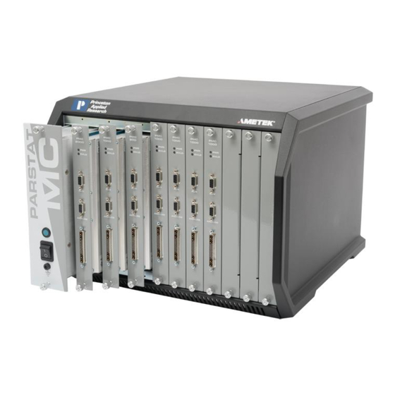
PMC-200 Hardware Manual P/N XXXXXX REPLACING MODULES OF THE PARSTAT MC CHASSIS Figure 11. PARSTAT MC. 1 x PMC CHS08A and 8 x PMC-2000 channels 4.1. Introduction The PARSTAT MC (PMC) is a multi-channel potentiostat system with a unique modular design. -
Page 23: Safety Information
PMC-200 Hardware Manual P/N XXXXXX 4.1.1. Safety Information This manual contains up to three levels of safety instructions that must be observed to avoid personal injury and/or damage to equipment or other property. These are: Safety Keywords: DANGER Indicates a hazard that could result in death or serious bodily harm if the safety instruction is not observed. - Page 24 PMC-200 Hardware Manual P/N XXXXXX Figure 12. Power Supply module (PMC PWR01). On the front panel of the power supply module is the main power switch for the PMC. When the switch is toggled up (I), power is ON. When the switch is toggled down (O), power is OFF. The power indicator LED lamp is lit when power is ON and unlit when power is OFF.
-
Page 25: The Potentiostat Module
PMC-200 Hardware Manual P/N XXXXXX Figure 13. Back of the PWR01 after the removal from the CHS08A. The rear of the power supply module has the power entry for AC mains power, the locators and connector to the backplane module, and two fuse holders. - Page 26 PMC-200 Hardware Manual P/N XXXXXX Figure 14. The PMC-2000 Potentiostat Channel The front panel of the PMC channel has the cell cable connector, an analog connector, an auxiliary connector, and two LED indicators. When the PWR LED is lit, the channel is receiving power. When the OVLD LED is lit, an overload condition exists on that channel.
-
Page 27: The Blank Module
PMC-200 Hardware Manual P/N XXXXXX Figure 15. Back of the uninstalled PMC Channel The back of the potentiostat channel has the locators and connections to the backplane, a signal connector and a power connector. CAUTION Do not remove any covers or panels from the potentiostat module. - Page 28 PMC-200 Hardware Manual P/N XXXXXX Figure 16. Front view of the Blank Module (Ametek P/N 224262). Figure 17. Angled view of the Blank Module. PMC-200 Hardware Manual...
-
Page 29: The Fan Module (Pmc Fan01)
PMC-200 Hardware Manual P/N XXXXXX The blank module has top and bottom thumbscrews that fasten the module to the front of the chassis. This module has top and bottom edges that help locate the module in the chassis, aligning and retaining it properly. - Page 30 PMC-200 Hardware Manual P/N XXXXXX Figure 18. Front View of the PARSTAT MC. Turn the top and bottom thumbscrews on the front of the power supply module anti-clockwise (toward the left) until the thumbscrews are disconnected from the chassis. Then pull firmly on the thumbscrews until the power supply module slides out of the chassis.
- Page 31 PMC-200 Hardware Manual P/N XXXXXX When the power supply module is removed from the chassis it may be packaged for shipment. To install a new power supply module into the chassis, first locate the card guides for the power supply module in the chassis.
-
Page 32: Replacing A Fuse On The Power Supply Module
PMC-200 Hardware Manual P/N XXXXXX Figure 21. PMC PWR01 power supply with card guides identified. Slide the power supply module into the chassis until the front panel of the module meets the front of the chassis. Fasten the thumbscrews to the chassis by inserting them into the threaded holes in the chassis and turning them clockwise (toward the right) until they are finger tight. -
Page 33: Installing A New Potentiostat Channel
PMC-200 Hardware Manual P/N XXXXXX To remove the fuse, grasp the knob at the end of the fuse holder and turn anti-clockwise (toward the left) until the end of the holder comes loose and the fuse cartridge pulls out of the holder. See Table 1 for replacement fuse values. - Page 34 PMC-200 Hardware Manual P/N XXXXXX Remove the blank module by turning the top and bottom thumbscrews anti-clockwise (toward the left) until the thumbscrews are disconnected from the chassis. Then pull firmly on the thumbscrews until the blank module slides out of the chassis.
- Page 35 PMC-200 Hardware Manual P/N XXXXXX Figure 25. Card guides of PMC CHS08A identified for a PMC channel installation Align the top and bottom PCB edges of the potentiostat module with the top and bottom card guides in the chassis. Slide the potentiostat module into the chassis until the front panel of the module meets the front of the chassis.
-
Page 36: Replacing An Existing Potentiostat
PMC-200 Hardware Manual P/N XXXXXX Insert the thumbscrews into the threaded holes in the chassis and turn the thumbscrews clockwise (toward the right) until they are finger tight. 4.4. Replacing an existing potentiostat It is not necessary to turn off power to the instrument to replace a potentiostat channel. The other channel(s) in the instrument may continue to operate normally during this procedure. - Page 37 PMC-200 Hardware Manual P/N XXXXXX Figure 27. PARSTAT MC with PMC Channel being removed. Remove the potentiostat module by turning the top and bottom thumbscrews anti-clockwise (toward the left) until the thumbscrews are disconnected from the chassis. Then pull firmly on the thumbscrews until the module slides out of the chassis.
- Page 38 PMC-200 Hardware Manual P/N XXXXXX CAUTION Do NOT operate the PMC with an empty slot any longer than necessary to insert another module into that slot. Insert the new blank module into the now empty slot by locating the card guides for this slot.
- Page 39 PMC-200 Hardware Manual P/N XXXXXX Figure 29. PMC CHS08A with a temporary Blank Module being installed. Insert the thumbscrews into the threaded holes in the chassis and turn the thumbscrews clockwise (toward the right) until they are finger tight. PMC-200 Hardware Manual...
-
Page 40: Replacing The Fan Module
PMC-200 Hardware Manual P/N XXXXXX Figure 30. PMC CHS08A with a 7 x PMC Channels and 1 x Blank Module in place. When the replacement potentiostat module arrives, unpackage the new module and remove the blank module from the chassis. - Page 41 PMC-200 Hardware Manual P/N XXXXXX Figure 31. Rear view of a PARSTAT MC. Remove the rear cover from the chassis and set it aside. PMC-200 Hardware Manual...
- Page 42 PMC-200 Hardware Manual P/N XXXXXX Figure 32. PMC CHS08A with back cover removed to access PMC FAN01 for replacement. Disconnect the three wire harnesses that connect the fans to the fan control board. PMC-200 Hardware Manual...
- Page 43 PMC-200 Hardware Manual P/N XXXXXX Figure 33. The PMC CHS08A with the 3 x wire harnesses shown as part of replacing the PMC FAN01 Then, unfasten the three screws across the bottom of the fan plate and remove the fan module from the chassis.
- Page 44 PMC-200 Hardware Manual P/N XXXXXX Figure 34. PMC CHS08A showing the removal of the PMC FAN01 Fan Module. Remove the eight screws that hold the fan control card to the backplane. PMC-200 Hardware Manual...
- Page 45 PMC-200 Hardware Manual P/N XXXXXX Figure 35. PMC CHS08A shown with the PMC FAN01 removed. Pull the fan control card straight back from the backplane. When the fan control card is disconnected from the backplane, the fan control card and the fan module may be packaged for shipment to the factory.
- Page 46 PMC-200 Hardware Manual P/N XXXXXX Figure 36. PMC CHS08A with Fan Assembly and Wire Harness Uninstalled. Place the fan module up to the back of the chassis with the fan plate up against the chassis. Insert three screws across the bottom of the fan plate and fasten them to the chassis.
- Page 47 PMC-200 Hardware Manual P/N XXXXXX Figure 37. PMC CHS08A with wire fan harness (x3) identified. Connect a fan wire harness from the left fan to the left-most connector on the fan card, a second fan wire harness from the center fan to the center connector on the fan card, and a third fan wire harness from the right fan to the right-most connector on the fan card.
-
Page 48: Replacing The Backplane Module
PMC-200 Hardware Manual P/N XXXXXX Figure 38. PMC CHS08A Rear Panel with USB and AC Power Identified. Now the AC mains cable and USB cable may be connected and the instrument may be powered ON. 4.6. Replacing the Backplane Module To replace the backplane module, first toggle the main power switch down (O) to the OFF position. - Page 49 PMC-200 Hardware Manual P/N XXXXXX Figure 39. Empty PMC CHS08A in preparation to remove PMC BPLN Disconnect the USB cable from the back of the instrument. Using a suitable Phillips or cross-point screwdriver, remove the screws holding the back cover.
- Page 50 PMC-200 Hardware Manual P/N XXXXXX Figure 40. PMC CHS 08A identifying USB and AC cables disconnected. Disconnect the three wire harnesses that connect the fans to the fan control board, and remove the eight screws that hold the fan control card to the backplane.
- Page 51 PMC-200 Hardware Manual P/N XXXXXX Figure 41. PMC CHS08A showing wire harness (x3) and screws (x8) for removal. Pull the fan control card straight back from the backplane. Once the fan card is disconnected from the backplane, set it aside.
- Page 52 PMC-200 Hardware Manual P/N XXXXXX Figure 42. PMC CHS08A with screws and standoffs for PMC BPLN removal Remove the ten screws holding the backplane to the chassis. Using a ¼” nut driver, remove the three standoffs holding the backplane to the chassis and pull the backplane out.
- Page 53 PMC-200 Hardware Manual P/N XXXXXX Figure 43. The PMC CHS08A with the BackPlane (PMC BPLN) being removed. The backplane module may now be packaged for shipment to the factory. Be sure to keep the fan control card for use with the new backplane.
- Page 54 PMC-200 Hardware Manual P/N XXXXXX Figure 44. PMC CHS08A with the new PMC BPLN insalled. Install three standoffs provided in the locations shown. Install the fan control card. For instructions on installing the fan control card, refer to the section Replacing the fan module.
- Page 55 PMC-200 Hardware Manual P/N XXXXXX Figure 45. PMC CHS08A showing screw installation for the rear panel. The power supply module may now be installed into the chassis. For instructions, refer to the section Replacing the power supply module. The potentiostat and blank modules may be installed. For instructions, refer to the section Replacing a potentiostat module.
-
Page 56: Airflow Considerations
PMC-200 Hardware Manual P/N XXXXXX 4.7. Airflow considerations To ensure reliable performance and long life of the PMC, optimum airflow must be maintained during operation. The following precautions will assist in this regard: Do not operate the PMC with missing modules or empty slots. - Page 57 PMC-200 Hardware Manual P/N XXXXXX CAUTION Do NOT block air inlets or exhaust. PMC-200 Hardware Manual...
-
Page 58: Specifications And Pinouts
PMC-200 Hardware Manual P/N XXXXXX SPECIFICATIONS AND PINOUTS 5.1. Electronic Specifications of the PMC-200 5.1.1. System Performance Minimum Time Base: 4 µs Minimum Current Range: 2 µA Minimum Current Resolution: 240 fA 5.1.2. Power Amplifier Compliance Voltage: +10 V Maximum Current: +1 A 5.1.3. -
Page 59: Bandwidth Limits
The PMC-200 defaults to the "Full" setting as the instrument is designed to be stable in most user cases. If the "Full" setting does not work with the cell and the user suspects the cell is oscillating, it is recommended to start with 100 kHz and work towards slower settings until the system is stable. -
Page 60: Cell Cable Pinouts
PMC-200 Hardware Manual P/N XXXXXX 5.5. Cell Cable Pinouts Table 2. PMC-200 Cell Cable Pin Outs Signal Function COUNTER See section 3.4.2. REFERENCE See section 3.4.2. GROUND See section 3.4.2. SENSE See section 3.4.2. WORKING See section 3.4.2 COUNTER Twisted with Pin 1... -
Page 61: Available Options
Figure 16. The PMC-2000 Potentiostat Channel ................26 Figure 17. Back of the uninstalled PMC Channel ................27 Figure 18. Front view of the Blank Module (Ametek P/N 224262)..........28 Figure 19. Angled view of the Blank Module..................28 Figure 20. - Page 62 PMC-200 Hardware Manual P/N XXXXXX Figure 34. PMC CHS08A with back cover removed to access PMC FAN01 for replacement. . 42 Figure 35. The PMC CHS08A with the 3 x wire harnesses shown as part of replacing the PMC FAN01 ................................. 43 Figure 36.
Need help?
Do you have a question about the PMC-200 and is the answer not in the manual?
Questions and answers