
Related Manuals for Ametek TAYLOR HOBSON FORM TALYSURF PGI NOVUS


Summary of Contents for Ametek TAYLOR HOBSON FORM TALYSURF PGI NOVUS
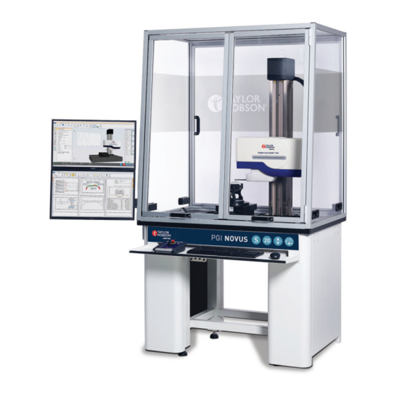
- Page 1 OPER ATOR GUIDE FORM TALYSURF ® FORM TALYSURF ® PGI NOVUS www.taylor-hobson.com © Taylor Hobson Ltd. 2023.
- Page 2 PGI NOVUS FORM TALYSURF ® Introductory operator guide This is Taylor Hobson’s safety & installation information guide for the Form Talysurf PGI NOVUS. ® All the specifications in this document are correct at time of production and are subject to change. Please contact Taylor Hobson for further information.
-
Page 3: Table Of Contents
Contents Introduction ................. 4 Start up procedure ..............5 Metrology 4.0 software ............. 6 User interface .......................7 Selecting the stylus ..................16 Calibration ..................18 Single bias calibration ..................18 Dual bias calibration ..................20 Calibration procedure - good and bad results ......23 Calibration artefacts ..................24 Measurement ................26 2D measurement ....................26 3D measurement ....................28... -
Page 4: Introduction
Introduction Form Talysurf PGI NOVUS instruments are modular, high precision ® instruments for the measurement of surface texture, form and diameter. They offer the right balance of capability, automation and capacity for virtually every application and budget with specific options for the bearings and optics industries. -
Page 5: Start Up Procedure
Start up procedure Note Please follow the optimised start up procedure to ensure quick and easy start up of PGI NOVUS and Metrology 4.0: 1. Switch on PGI NOVUS mains supply via switches located on the rear and side of the instrument. 2. -
Page 6: Metrology 4.0 Software
Metrology 4.0 software Metrology 4.0 incorporates all features that are crucial in measurement and analysis. The software has the added ability of having its own fully automated 3D instrument view which allows a true visualisation of the measurement platform on a computer screen. The software platform is split up into 3 distinct sections: Instrument, Analysis and Production Interface. -
Page 7: User Interface
User interface Instrument ribbon Change/select bias of Contact - move stylus the PGI Gauge into contact with part Part co-ordinate system Clear all PCS (PCS) Control - all instrument Gauge calibration axes and stages Lift /lower force Stylus force calibration calibration Gauge settings - set Show TV view (real time... - Page 8 Change stylus bias The PGI NOVUS has the option to be fitted with a dual bias gauge. If this option has been configured, then measurements can be taken in ‘Normal’ or ‘Reverse’ bias. To select between each bias, click on the ‘Change bias’ icon and use the drop-down box to select the desired direction.
- Page 9 Move to position in Move by distance in X-axis X-axis Continuous negative Continuous positive move in Z-axis move in Z-axis Move to position in Move by distance in Z-axis Z-axis Continuous negative Continuous positive move in Y-axis move in Y-axis Move to position in Move by distance in Y-axis...
- Page 10 The icons for secondary stages will be displayed in grey. An example of ‘Move to position’ is shown below. X-stage (X Second Y-stage (Y Second rotary stage (θ Instrument control - inputs • Speed - The speeds for each axes can be set independently. Look through the drop-down list for available speeds or type in a value (as long as it is within the minimum and maximum limits of the system).
- Page 11 TV view and measurement chart Both the TV view and measurement chart show the measurement in real time through the on-screen profile. This is most beneficial if any dirt, marks or obscurities are seen, as the measurement can be stopped at any point, without any loss of data.
- Page 12 Save as Verify program Program properties Run program Run program Pause program continuously Run program ‘n’ times Step through program Run program from step Stop program Record program 1. New - To start a new program, click the ‘New’ icon. A blank program tab will appear each time the ‘New’...
- Page 13 6. Save/Save as - Save the program by clicking the ‘Save as’ icon. A Windows explorer menu will appear where a location to save the file can be defined. Once the program has been saved once, the ‘Save’ icon can then be clicked save the program.
- Page 14 Measurement toolbar The measurement toolbar is used for all types of measurement. The available measurements will vary depending on the configured instrument. 2D X-axis measurement 3D Measurement Discontinuous Internal diameter measurement measurement Crest analysis - LS Arc, Crest measurement highest, lowest and turning point.
- Page 15 Instrument configuration menu Instrument/system Configure the system’s configurator device performances Add, edit or remove Add or remove stylus calibration artefacts Configure the upper and Gauge alignment routine lower system end stops Configure axis park Set and calibrate axis settings reference positions Safe reset Center of rotation Change lift/lower...
-
Page 16: Selecting The Stylus
Save profile Load profile Import part Preferences Export settings Import settings Reference guide (Help) View Licence About Metrology 4.0 Selecting the stylus To select a stylus, acces the configuration dialog box. 1. Navigate to the ‘Gauge’ section of the instrument ribbon and click on the ‘Settings’... - Page 17 Note If the selected stylus has previously been calibrated then it is possible to restore that last calibration. Please note it is best-practise metrology to re-calibrate after replacing the stylus to ensure the more accurate results. Adding a new stylus To add a new stylus to Metrology 4.0, acces the ‘Gauge’...
-
Page 18: Calibration
Calibration Single bias calibration A calibration is required on the gauge to ensure the acurate motion of the stylus has been corrected. This ensures that the measurement is accurate and reliable. Automated calibration procedure steps are below: 1. Navigate to the ‘Gauge’ section of the instrument ribbon and click on the ‘Calibration’... - Page 19 4. When the calibration routine is complete, the results will appear in the analysis section of Metrology 4.0. 1. Calibration artefact - The artefact in use can be selected using the drop- down list, with information displayed to the right of the list. 2.
-
Page 20: Dual Bias Calibration
Dual bias calibration A calibration is required on the gauge to ensure the acurate motion of the stylus has been corrected and tip to tip size is calculated. This ensures that the measurement is accurate and reliable. Automated calibration procedure steps are below: 1. - Page 21 3. Follow the on-screen instructions. Click ‘Next’ to continue through the calbiration procedure. Note: Messages/instructions will appear differently depending on procedure selected and If auto Y-stage fitted. 4. When the calibration routine is complete, the results will appear in the analysis section of Metrology 4.0.
- Page 22 1. Calibration artefact - The artefact in use can be selected using the drop- down list, with information displayed to the right of the list. 2. Stylus - The stylus being used for the calibration can be selected from the drop down list. Part number and basic information about the stylus dimensions are displayed within this list.
-
Page 23: Calibration Procedure - Good And Bad Results
Calibration procedure - good and bad results Illustrations below show the differences between good, bad and acceptqable calibration profiles. Bad calibrations can be caused by dirt on calibration artefacts, damaged styli and/or damaged gauge. 1. Good calibration 2. Bad calibration - curves up at edge 3. -
Page 24: Calibration Artefacts
Calibration artefacts Maintenance of calibration artefacts can be conducted by navigating to the ‘Gauge’ section of the ‘Instrument calibration’ menu. There is the option to add, edit or remove a range of different calibration artefacts including: Calibration ball Step height Ra patch Dual bias calibration hemisphere with... - Page 25 Adding a new calibration artefact To add a new calibration artfact to Metrology 4.0, acces the ‘Gauge’ tab in the ‘Instrument Configuration’ section. 1. Select the ‘Calibration artefact’ icon. 2. Click ‘New’, and select the type of calibration artefact required from the list. 3.
-
Page 26: Measurement
Measurement Making a 2D measurement 2D measurements are used to measure single profiles in the X direction. Measurements can be made in normal or reverse bias directions.The measurement procedure steps are below: 1. Navigate to the ‘Measurement toolbar’ and click on the ‘2D X Measurement’... - Page 27 1. Measurement name - This is used to distinguish between measurements. The idea is to give the measurement a clear name which can be easily identified later. There is an option to auto-increment from a certain value which can improve the ability to distinguish between measurements and prevent overwrites.
-
Page 28: Measurement
Making a 3D measurement 3D measurements use multiple profiles to generate surfaces. 3D measurements are a result of multiple scans, over a surface using both the X and Y-stages. 1. Navigate to the ‘Measurement toolbar’ and click on the ‘3D Measurement’ icon. 2. - Page 29 1. Measurement name - This is used to distinguish between measurements. The idea is to give the measurement a clear name which can be easily identified later. There is an option to auto-increment from a certain value which can improve the ability to distinguish between measurements and prevent overwrites.
- Page 30 T HE ME T R O L O GY E X P E R T S Taylor Hobson UK Taylor Hobson China Tel: +44 (0)116 276 3771 taylor-hobson-china.sales@ametek.com taylor-hobson.sales@ametek.com Shanghai Office Tel: +86 21 5868 5111-110 Taylor Hobson France Beijing Office...
Need help?
Do you have a question about the TAYLOR HOBSON FORM TALYSURF PGI NOVUS and is the answer not in the manual?
Questions and answers