Table of Contents
Advertisement
Quick Links
Advertisement
Table of Contents

Subscribe to Our Youtube Channel
Related Manuals for Ametek VersaSTAT MC


Summary of Contents for Ametek VersaSTAT MC
- Page 1 VersaSTAT MC Hardware Manual P/N 224185...
-
Page 2: Table Of Contents
VersaSTAT MC Hardware Manual Contents Safety Instructions and Symbols ........................4 Cleaning Instructions ............................. 4 1. INTRODUCTION ............................5 1.1. General .............................. 5 1.2. Hardware Circuitry ..........................5 1.2.1. Potentiostatic mode ........................6 1.2.2. Galvanostatic mode ........................7 1.3. Software ............................. 7 1.4. - Page 3 4.5. Cell Cable Pinouts ................Error! Bookmark not defined. 5. AVAILABLE OPTIONS ..........................26 5.1 2A High Current Option ........................26 5.2 Advanced Auxiliary Interface Option ....................26 5.3 Power Booster ..........................26 Appendix 1..............................28 VersaSTAT MC External Power Booster Connections................29...
-
Page 4: Safety Instructions And Symbols
VersaSTAT MC Hardware Manual Safety Instructions and Symbols This manual contains up to three levels of safety instructions that must be observed in order to avoid personal injury and/or damage to equipment or other property. These are: DANGER Indicates a hazard that could result in death or serious bodily harm if the safety instruction is not observed. -
Page 5: Introduction
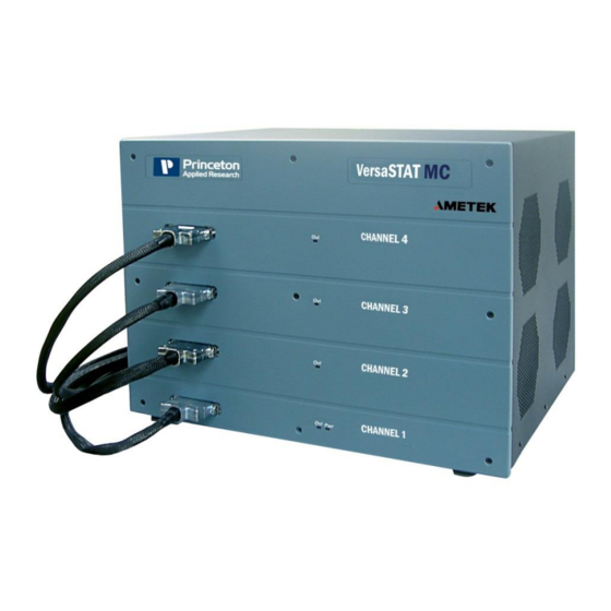
VersaSTAT MC Hardware Manual 1. INTRODUCTION The VersaSTAT MC (Figure 1), teamed with the VersaStudio software package, comprises a simple, flexible, and extremely powerful system for performing a wide range of electrochemical techniques. The VersaSTAT MC is a potentiostat/galvanostat with up to four (4) channels in a single chassis. -
Page 6: Potentiostatic Mode
1.2.1. Potentiostatic mode In this mode, the VersaSTAT MC controls the potential at the working-sense electrode with respect to the reference electrode (see Figure 2). The counter electrode is driven to the potential required (consistent with the + 12 V compliance of the control amplifier) to establish the desired working potential. -
Page 7: Galvanostatic Mode
Figure 3. Galvanostat-Mode Block Diagram 1.3. Software The VersaSTAT MC is fully compatible with the VersaStudio software only. VersaSTAT MC will not operate with any other software other than that specified in this manual most recent... -
Page 8: Inspecting Your New Instrument
1.5. Inspecting Your New Instrument As soon as you receive your new VersaSTAT MC, inspect it for shipping damage. If any damage is noted, immediately notify Princeton Applied Research and file a claim with the carrier. - Page 9 VersaSTAT MC Hardware Manual Chapter 3 shows how to set up the hardware. It describes the functions of the connections and indicator lights, and shows how to connect the VersaSTAT MC to the host computer and test cell. Chapter 4 gives the physical and electrical specifications of the VersaSTAT MC including the AUXILIARY INTERFACE connector pinouts.
-
Page 10: Safety And Component Placement
RF interference and transient sensitivity. 2.1. Safety Considerations 2.1.1. Line Voltage Settings and Fuses The VersaSTAT MC has a Corcom™ Power Entry Module on the left side of the rear panel. The Corcom module (pictured below) contains the power connector and two line fuses. -
Page 11: Defects And Abnormal Stresses
Do not operate damaged equipment! Tag it to indicate to a potential user that it is unsafe to operate. The VersaSTAT MC’s ground protection is likely to be impaired if, for example, the instrument shows visible damage ... -
Page 12: Ventilation
2.2.2. Radio Frequency Interference In a typical application, it is unlikely that the VersaSTAT MC will act as a source of noticeable RF interference. However, when operated near particularly sensitive equipment, interference from the VersaSTAT MC could be a problem. -
Page 13: Transient Sensitivity
VersaSTAT MC Hardware Manual In the case of a signal lead, it is essential that the capacitor’s value be such as to attenuate the interference frequencies without unduly attenuating critical frequency components of the signal itself. NOTE: Keep the filter capacitor leads short! Long leads establish sizable ground loops and could additionally act as radiating antennae. - Page 14 VersaSTAT MC Hardware Manual Static discharge problems can sometimes be avoided by judiciously selecting the floor covering in the work area. The simplest approach to the problem is to discharge your body by touching a grounded metal object just before touching the instrument, particularly when making connections to the cell.
-
Page 15: Installation
3.1. Enabling the USB port on your PC Some PC manufacturers ship their PCs with the USB port disabled. Check for this before trying to use the VersaSTAT MC. If the port is disabled, follow the manufacturer’s instructions for enabling it. - Page 16 Attach the supplied USB cable to this connector and to the USB connector on the PC. You can connect to and disconnect from the PC without shutting down or restarting Windows or VersaStudio. FIGURE 5. VersaSTAT MC Rear Panel 3.2.1.3. SYNC ADC INPUT This BNC (one per channel) allows you to monitor an auxiliary signal in the + 10 V range with 16-bit resolution.
-
Page 17: Front Panel
VersaStudio software. See Section 4.4. for the pin assignments. 3.2.2. Front Panel The VersaSTAT MC front panel is shown in Figure 7. The front panel below has all four channels installed. Those systems with less than four channels do not have the connectors and indicators listed below. -
Page 18: Connecting To The Pc And Cell
3.3. Connecting to the PC and Cell This section gives instructions on connecting the VersaSTAT MC to the host PC and to electrochemical cell and other equipment. WARNING: For operator and equipment safety, power to all instruments should be off when connecting or disconnecting cables. - Page 19 VersaSTAT MC and causing damage to the instrument. 4. The opposite end of cell cable for the VersaSTAT MC is color-coded at the tip as follows: Green – Working (WE) electrode lead. This lead connects to the electrode of interest at which the desired reactions will occur.
- Page 20 VersaSTAT MC Hardware Manual Figure 8. Two-Electrode Connection b) General aqueous electrochemistry, corrosion experiments, and most EIS experiments are connected using a three-terminal connection (Figure 9). The voltage at the working-sense is controlled relative to a stable reference electrode positioned in close proximity to the working electrode.
- Page 21 This is necessary to establish the correct polarity relationship at the working electrode versus the reference electrode. 7. After all other connections to the VersaSTAT MC are complete, experiments can be set up and performed. VersaSTAT 3F Hardware Manual...
-
Page 22: Specifications And Pinouts
VersaSTAT MC Hardware Manual 4. SPECIFICATIONS AND PINOUTS 4.1. Electronic Specifications 4.1.1 System Performance Minimum Time Base: 10 μs Minimum Potential Step: 1 uV Noise and Ripple < 50 μV rms typical Minimum Current Range 200 nA (hardware) ... -
Page 23: Voltage Measurement
VersaSTAT MC Hardware Manual 4.1.6. Voltage Measurement Voltage Range + 10 V maximum Minimum Voltage Resolution + 6 uV Voltage Accuracy + 0.2% reading, + 2 mV 4.1.7. Current Measurement Ranges 8 decades, 2A (650mA max.) to 200 nA Accuracy (dc) ... -
Page 24: Physical And Power Specifications
VersaSTAT MC Hardware Manual 4.2. Physical and Power Specifications Computer Interface Universal Serial Bus (USB) Weight 4.5 kg (10 lbs) Dimensions 42.1 cm W x 38.7 cm D x 8.9 cm H (16.25 in x 15.25 in x 3.5 in ) Power Requirements ... -
Page 25: Auxiliary Interface Pinouts
VersaSTAT MC Hardware Manual 4.4. AUXILIARY INTERFACE Pinouts Signal Function Ground TRIG IN Using the VersaStudio software, an experiment can be held, waiting on this TTL trigger input signal to be read. DISPENSE When using the PARSTAT 4000 with a Model 303 or 303A... -
Page 26: Available Options
4. VersaSTAT Low Current Interface 5.1 2A High Current Option The 2A High Current Option for the VersaSTAT MC expands the upper applied and measured current from the base 650mA up to 2A. This option is built into the base unit,... -
Page 27: Appendix 1
Each power booster includes an external power supply interfaced to additional internal circuitry of the VersaSTAT MC system via the rear panel. Once connected, the VMC can be operated in either boosted mode or normal mode depending on a switch setting at the rear panel, as well as some cell cable changes. - Page 28 VersaSTAT MC Hardware Manual Advanced Measurement Technology, Inc. a/k/a Princeton Applied Research, a subsidiary of AMETEK®, Inc. WARRANTY Princeton Applied Research* warrants each instrument of its own manufacture to be free of defects in material and workmanship. Obligations under this Warranty shall be limited to replacing, repairing or giving credit for the purchase price, at our...
-
Page 29: Versastat Mc External Power Booster Connections
Appendix 1. VersaSTAT MC External Power Booster Connections General The External Power Booster option for the VersaSTAT MC is (all power ratings are nominal as determined by bipolar power supply): The 20A/VMC provides ± 20 amps This add-on option consists of a specially configured bipolar power supply from KEPCO®, Inc., an internal (inside VersaSTAT MC chassis) Princeton Applied Research... - Page 30 The VersaSTAT MC and KEPCO connect to the cell (electrochemical cell, battery, etc.) by two marked cables, 223873 for the KEPCO and 223859 for the VersaSTAT MC (replacing the normal cell cable used for “Normal” mode). All the interconnections for the VersaSTAT MC and KEPCO are shown below.
- Page 31 VersaSTAT MC Hardware Manual KEPCO Front-Panel Setup The MODE switch on the front panel of the KEPCO should be set to Voltage mode (left position). The Voltage CONTROL switch (red toggle on left side) should be in the OFF (down) position.
- Page 32 5 watts. Dummy Cell Connections 1. Ensure the power is off on both the VersaSTAT MC and KEPCO. 2. Connect dummy cell (resistor) as shown above with Counter/Reference connected to one side of the resistor, and Working/Sense connected to the opposite side.
- Page 33 VersaSTAT MC Hardware Manual the “Advanced” button and set the “Electrometer Mode” to the setting of “Differential.” 9. Select the “Run” button at the top of the window to start the experiment and acquire data. 10. After the experiment finishes, verify that the applied potential was 1V, and that the resulting current was 1A (for a 1 ohm resistor) for the data (10 points) collected..
Need help?
Do you have a question about the VersaSTAT MC and is the answer not in the manual?
Questions and answers