
Subscribe to Our Youtube Channel
Related Manuals for Ametek mocon OX-TRAN 2/48


Summary of Contents for Ametek mocon OX-TRAN 2/48
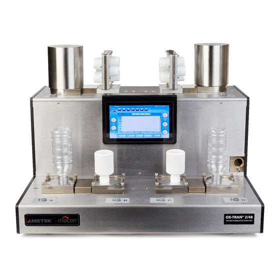
- Page 1 OX-TRAN ® Model 2/48 Operator’s Manual Revision E Lauper Instruments AG Gas-Detection Irisweg 16B CH-3280 Murten Tel. +41 26 672 30 50 info@lauper-instruments.ch www.lauper-instruments.ch Part Number 143-218...
- Page 2 Trademarks & Patents MOCON, COULOX, and OX-TRAN are registered trademarks of Mocon, Inc. For information on applicable patents see: https://www.ametekmocon.com/aboutus/legal/intellectualproperty Copyright© 2021 MOCON, Inc. All rights reserved.
- Page 3 OX-TRAN Model 2/48 H Operator’s Manual About This Manual About This Manual This manual explains how to set up and use the OX-TRAN Model 2/48 Oxygen Transmission Rate System. This manual is designed for viewing electronically. Most references to other sections or chapters in this document are hyperlinks which can be used to navigate to the referenced section.
-
Page 4: Safety Information
Safety Information OX-TRAN Model 2/48 H Operator’s Manual Safety Information Be sure to read and understand this section and all other applicable chapters of the Operator's Manual and all on-product safety signs before setting up, operating, and maintaining this analyzer. Safety signs appear in this manual and on the analyzer. -
Page 5: Table Of Contents
OX-TRAN Model 2/48 H Operator’s Manual Table of Contents Table of Contents About This Manual ............................iii Safety Information ............................iv Chapter 1: Introduction..........................1-1 Features ............................... 1-2 Measuring an Oxygen Transmission Rate .................... 1-3 Testing Packages and Films ........................ 1-4 Permeation Test Overview ........................ - Page 6 Table of Contents OX-TRAN Model 2/48 Operator’s Manual Humidified Environment Testing ......................3-8 Filling the Carrier Gas Water Reservoir ..................3-8 Loading and Unloading a Test Cartridge ....................3-9 Chapter 4: Using the Instrument Software....................4-1 Software Features ..........................4-1 Instrument Software Structure and Organization ..................
- Page 7 OX-TRAN Model 2/48 H Operator’s Manual Table of Contents Transmission Rate Measurement Capabilities ..................9-3 Appendix A: Site Preparation Instructions ....................A-1 Appendix B: Spare Parts .......................... B-1 Appendix C: Warranty and Service Policies ..................... C-1 Appendix D: Theory of Operation ......................D-1 How the Oxygen Sensor Works ......................
- Page 8 Table of Contents OX-TRAN Model 2/48 Operator’s Manual Figures Figure 1-1: OX-TRAN Model 2/48 System ....................1-1 Figure 1-2: An OX-TRAN Model 2/48 Permeation Cell ................1-3 Figure 1-3: Large Tray Cartridge ....................... 1-4 Figure 1-4: Package Adapter Cartridge ..................... 1-4 Figure 1-5: Bottle &...
-
Page 9: Chapter 1: Introduction
OX-TRAN Model 2/48 Operator’s Manual Introduction Chapter 1: Introduction This chapter provides a brief overview of the OX-TRAN Model 2/48 Oxygen Transmission Rate System. Read this chapter to get an overview of: The features of the OX-TRAN Model 2/48 system •... -
Page 10: Features
Introduction OX-TRAN Model 2/48 Operator’s Manual Features The following features of the OX-TRAN Model 2/48 Oxygen Transmission Rate System make it very versatile and easy to use: Fully automatic (Hands Off) testing. • Four Test Cells to provide increased test capacity. •... -
Page 11: Measuring An Oxygen Transmission Rate
OX-TRAN Model 2/48 Operator’s Manual Introduction Measuring an Oxygen Transmission Rate To make an accurate transmission rate measurement a Test Gas (20.9% oxygen) is applied to one side of the barrier material to be tested and the other side is swept with an oxygen free Carrier Gas (usually a nitrogen/hydrogen mix). -
Page 12: Testing Packages And Films
Introduction OX-TRAN Model 2/48 Operator’s Manual Testing Packages and Films To test packages (or films) the sample must be mounted in a Diffusion Cell. A Diffusion Cell exposes one side of the sample barrier to a Test Gas (ambient air in OX-TRAN Model 2/48) and the other side to a Carrier Gas. -
Page 13: Figure 1-5: Bottle & Cup Cartridge
OX-TRAN Model 2/48 Operator’s Manual Introduction Figure 1-5: Bottle & Cup Cartridge Figure 1-6: Film Cartridge MOCON, Inc. REVISION E... -
Page 14: Permeation Test Overview
Introduction OX-TRAN Model 2/48 Operator’s Manual Permeation Test Overview A “Permeation Test” consists of up to two phases that are performed using a Test Cell. The “Cell” may contain a package cartridge or a film cartridge. The Test Phase (always present) is used to measure the transmission rate of the test sample. -
Page 15: Chapter 2: Setting Up
OX-TRAN Model 2/48 Operator’s Manual Setting Up Chapter 2: Setting Up This chapter provides information on how to set up an OX-TRAN Model 2/48 and prepare it for use. Read this chapter to learn about: Unpacking the System • • Preparing for System Installation •... -
Page 16: Front Panel Parts And Controls
Setting Up OX-TRAN Model 2/48 Operator’s Manual Front Panel Parts and Controls The names and locations of the parts and controls located on the front of the instrument are shown in Figure 2-1, and Error! Reference source not found.. Figure 2-1: Front Panel Parts and Controls Item Name Description Instrument Display... -
Page 17: Back Panel Parts And Controls
OX-TRAN Model 2/48 Operator’s Manual Setting Up Back Panel Parts and Controls The names and locations of the parts and controls located on the back of the instrument are shown in Figure 2-2 and Table 2.2. Figure 2-2: Back Panel Parts and Controls Item Name Description Power Inlet... -
Page 18: Top View Onboard Parts And Controls
Setting Up OX-TRAN Model 2/48 Operator’s Manual Top View Onboard Parts and Controls The names and locations of the parts and controls located on the back of the instrument are shown in Figure 2-3 and Table 2.3. Figure 2-3: Top View Onboard Parts and Controls Item Name Description Upper Deck... -
Page 19: Details Of Other Onboard Parts And Controls
OX-TRAN Model 2/48 Operator’s Manual Setting Up Details of Other Onboard Parts and Controls Figure 2-4: Carrier Gas Humidifier Figure 2-5: Test Cell Details MOCON, Inc. REVISION E... -
Page 20: Carrier Gas
Setting Up OX-TRAN Model 2/48 Operator’s Manual Item Name Description Water Reservoir - Carrier Gas Window showing the Carrier Gas Reservoir water level. Reservoir Fill Line The Carrier Gas Reservoir maximum level line. Reservoir Fill Port The fitting used to add water to the Carrier Gas reservoir. Test Cell Gas Ports The Test Cell Inlet, Outlet and TruSeal gas ports. -
Page 21: Connecting A Carrier Gas Supply
OX-TRAN Model 2/48 Operator’s Manual Setting Up Figure 2-6: System Plumbing Connection Diagram Connecting a Carrier Gas Supply Follow these steps to connect the Carrier Gas supply lines: Remove the brass plug from the Carrier Gas fitting on the instrument back panel. Save the plug it will be needed later. -
Page 22: Setting The Carrier Gas Supply Pressure
Setting Up OX-TRAN Model 2/48 Operator’s Manual Apply a thin coating of Apiezon grease to two compression ferrules. Cut a piece of tubing to connect the regulator tee on the previous instrument to the regulator tee on the next instrument. Connect the previous Carrier Gas regulator tee to the next Carrier Gas regulator tee using two nuts and ferrules. -
Page 23: Chapter 3: Preparing For A Test
OX-TRAN Model 2/48 H Operator’s Manual Preparing for a Test Chapter 3: Preparing for a Test This chapter provides information on how to prepare for a permeation test. Read this chapter to learn about: Testing Basics • • How Barrier Properties Affect Testing •... -
Page 24: Testing Mixed Barriers
Preparing for a Test OX-TRAN Model 2/48 H Operator’s Manual Testing Mixed Barriers Simultaneously testing barriers with widely divergent transmission rates is not recommended. The data for some or all of the individual samples may not be accurate when there is a large difference in the transmission rates between samples. -
Page 25: Individual Zero Processing
OX-TRAN Model 2/48 H Operator’s Manual Preparing for a Test Individual Zero Processing Adjusting the ReZero frequency will compensate for small shifts in the baseline zero. It may also be necessary to compensate for individual variations such as seal permeation and leakage in the Test Cartridge. -
Page 26: Purging The Sample
Preparing for a Test OX-TRAN Model 2/48 H Operator’s Manual Purging the Sample Most mounted package samples contain a significant volume of air on the Carrier side of the barrier material. Before the package cassette is loaded and clamped into a Test Cell this volume contains oxygen from the ambient environment. -
Page 27: Conditioning The Sample
OX-TRAN Model 2/48 H Operator’s Manual Preparing for a Test Conditioning the Sample OX-TRAN Model 2/48 comes with 4 stations on the conditioning deck. Four samples can be conditioned while other four samples on being tested on the testing deck. Sample Conditioning is a test state that allows the sample barrier to acclimate to the specified test conditions. -
Page 28: Using The Automatic Check Function
Preparing for a Test OX-TRAN Model 2/48 H Operator’s Manual Using the Automatic Check Function Mounting packages in a manner that ensures the Carrier Gas side of the cell is free of leaks can be very difficult. Any imperfections in the seals used to mount the sample package to the Package Cassette can result in excessive levels of oxygen entering the Carrier Gas side of the cell. -
Page 29: Determining When To Stop A Test
OX-TRAN Model 2/48 H Operator’s Manual Preparing for a Test Determining When to Stop a Test The setting used for the “Test Mode” parameter determines how and when a transmission rate test is stopped (Test Completion). Four different methods of stopping a transmission rate test are provided. The four methods are: “Continuous”, “Standard”, “Convergence By Cycles”... -
Page 30: Humidified Environment Testing
Preparing for a Test OX-TRAN Model 2/48 H Operator’s Manual Humidified Environment Testing The OX-TRAN Model 2/48 has the capability of generating a controlled RH for the Carrier Gas. The generated RH range for the Carrier Gas is 50% - 90% RH. For the minimum RH that can be generated refer to the section on “Sample Conditioning Capabilities”... -
Page 31: Loading And Unloading A Test Cartridge
OX-TRAN Model 2/48 H Operator’s Manual Preparing for a Test Figure 3-2: Humidifier Fill Port and Controls Item Name Description Water Reservoir Window Window showing the Carrier Gas Reservoir water level Reservoir Fill Line The maximum level to which the reservoir should be filled. Fill Valve - Carrier Gas The screw used to open &... -
Page 32: Figure 3-3: Installing A Test Cartridge
Preparing for a Test OX-TRAN Model 2/48 H Operator’s Manual Hold the Test Cartridge firmly and lower it straight down over the clamp bar. Press the Clamp/Unclamp button on the deck of the Test Cartridge being installed. Figure 3-3: Installing a Test Cartridge 3-10 REVISION E MOCON, Inc. -
Page 33: Chapter 4: Using The Instrument Software
OX-TRAN Model 2/48 H Operator’s Manual Using the Instrument Software Chapter 4: Using the Instrument Software This chapter provides an overview of the software system used to operate the OX-TRAN Model 2/48. Detailed information on how to use the instrument software can be found in the Instrument Help System. Read this chapter to learn about: The Features and Capabilities of the Instrument Software •... - Page 34 Using the Instrument Software OX-TRAN Model 2/48 H Operator’s Manual Help System and a “close” button. The “Icon” bar is the fixed region below the Title bar containing seven icons. The “Workspace” occupies the remaining space below the Icon bar. The various functions and screens that appear within the workspace are accessed using the icons in the Icon bar.
-
Page 35: Chapter 5: Testing Packages
OX-TRAN Model 2/48 H Operator’s Manual Testing Packages Chapter 5: Testing Packages This chapter contains information on how to test packages. Suggestions on how to maximize the accuracy of your results and procedures describing how prepare for and perform a package test are discussed. Read this chapter to learn about: •... -
Page 36: Package Mounting Methods
Testing Packages OX-TRAN Model 2/48 H Operator’s Manual Package Mounting Methods There are many different types of packages and most of them can be tested on the OX-TRAN Model 2/48. Figure 5-1. To test packages a Diffusion Cell must be created to provide the required difference in permeant concentration across the barrier material. -
Page 37: Mounting Rigid And Semi-Rigid Packages
OX-TRAN Model 2/48 H Operator’s Manual Testing Packages Mounting Rigid and Semi-Rigid Packages A common characteristic of a rigid or semi-rigid package is an open area that must be sealed to create the Carrier Gas side of the Diffusion Cell. The perimeter of this open area usually contains a feature used to seal the filled package. -
Page 38: Mounting Packages Using A Package Adapter Cartridge
Testing Packages OX-TRAN Model 2/48 H Operator’s Manual A flexible package such as a bag or pouch does not contain a rigid planar surface that can easily be sealed to a mounting foil. The Flexible Package Test Cartridge is designed for testing fully sealed flexible bags and pouches. -
Page 39: Tube Mounting Packages
OX-TRAN Model 2/48 H Operator’s Manual Testing Packages Tube Mounting Packages A “tube mount” package fixture is created by sealing all unnecessary openings and then sealing two tubes into the package envelope to allow the Carrier Gas to “sweep” the interior. When “tube mounting” packages the carrier gas tubes can enter the top or bottom of the package. -
Page 40: Setting Up And Starting A Package Test
Testing Packages OX-TRAN Model 2/48 H Operator’s Manual Setting Up and Starting a Package Test After the samples are loaded and the instrument is ready there are several test parameters that must be set. There are two types of test parameters, cell parameters and instrument parameters. Cell Parameters are specific to each cell (Sample ID, Sample Thickness). -
Page 41: Chapter 6: Testing Flat Film Samples
OX-TRAN Model 2/48 H Operator’s Manual Testing Flat Film Samples Chapter 6: Testing Flat Film Samples This chapter contains information on how to test flat film samples. Suggestions on how to maximize the accuracy of your results and procedures describing how to perform the test are discussed. Read this chapter to learn about: •... -
Page 42: Preparing For A Film Test
Testing Flat Film Samples OX-TRAN Model 2/48 H Operator’s Manual If no testing will be performed for a significant period of time (overnight or weekend) no • special precautions are needed. The Gas Saver function will automatically be activated (when enabled) whenever both test cells are in the “Idle” state. Turning off the power and gas supplies to instrument is not recommended. -
Page 43: Orienting The Sample
OX-TRAN Model 2/48 H Operator’s Manual Testing Flat Film Samples Using a 5 cm mask will reduce the amount of oxygen sent to the sensor by a factor of 10 allowing a sample with an un-masked (50 cm area) transmission rate of 2000 cc / (m2 • day) to be tested safely. -
Page 44: Mounting A Sample In A Film Cartridge
Testing Flat Film Samples OX-TRAN Model 2/48 H Operator’s Manual Mounting a Sample in a Film Cartridge Follow the instructions below to mount a film sample in the Test Cell: Note: For information on cutting and preparing the film samples refer to the sections on “Sample Size”, “Using Masks”... -
Page 45: Sample Purging
OX-TRAN Model 2/48 H Operator’s Manual Testing Flat Film Samples Figure 6-1: Mounting a Film Sample Sample Purging The Film Test Cartridge does not normally need to be purged after mounting a sample. A permeation test always starts with a ReZero state. The time required to complete the ReZero is normally sufficient to properly purge the Film Test Cartridge. -
Page 46: Setting Up And Starting A Film Test
Testing Flat Film Samples OX-TRAN Model 2/48 H Operator’s Manual Setting Up and Starting a Film Test After the samples are loaded and the instrument is ready there are several test parameters that must be set. There are two types of test parameters, cell parameters and instrument parameters. Cell Parameters are specific to each cell (Sample ID, Sample Thickness). -
Page 47: Chapter 7: Maintenance
OX-TRAN Model 2/48 Operator’s Manual Maintenance Chapter 7: Maintenance This contains information on how to clean and maintain the OX-TRAN Model 2/48. Read this chapter to learn about: Cleaning the Instrument • • Maintaining the Test Cells • Maintaining the Oxygen (Coulox) Sensor •... -
Page 48: Maintaining The Test Cells
Maintenance OX-TRAN Model 2/48 Operator’s Manual Maintaining the Test Cells Periodically the test cell gas ports should be examined and any excess buildup of grease should be removed. Alcohol can be used to remove any residue from the Apiezon grease. Inspect the gas ports and TruSeal flush port and remove any grease that could obstruct the flow of gas. -
Page 49: Maintaining The Oxygen (Coulox) Sensor
OX-TRAN Model 2/48 Operator’s Manual Maintenance Maintaining the Oxygen (Coulox) Sensor Under normal use, the Coulox sensor supplied with your OX-TRAN Model 2/48 should last a year or more. The sensor could be damaged by accidents or by misuse such as continual exposure to high concentrations of oxygen. -
Page 50: System Standby
Maintenance OX-TRAN Model 2/48 Operator’s Manual Emptying the Carrier Gas Water Reservoir Before shutting down the instrument for long term storage or repair the Carrier Gas Water Reservoir must be drained and the chamber dried out to prevent any corrosion from occurring during storage or transport. To prepare the Carrier Gas Water Reservoir for storage or transport follow the procedure below: Advance all active tests to the Idle state. -
Page 51: Chapter 8: Troubleshooting
OX-TRAN Model 2/48 Operator’s Manual Trouble Shooting Chapter 8: Troubleshooting This chapter contains information to assist you in solving problems that may occur during the operation of the instrument. Read this chapter to learn about: • Error Messages and Warnings •... -
Page 52: Recovering From A Sensor Over-Range Condition
Troubleshooting OX-TRAN Model 2/48 Operator’s Manual Symptom: Abrupt changes in display readings or long-term cyclic oscillations. Comment: Unwanted data fluctuations observed during a test cycle may be caused by abrupt changes in the carrier gas flow rate. Such a transient symptom can be produced by a temporary restriction in any gas line, or gas usage by another system. -
Page 53: Chapter 9 Specifications
OX-TRAN Model 2/48 Operator’s Manual Specifications Chapter 9 Specifications This chapter contains the specifications of the OX-TRAN Model 2/48. Read this chapter for details about: • Environmental requirements • Electrical requirements Physical specifications • • Gas Supply requirements Operational capabilities •... -
Page 54: Sample Conditioning Capabilities
Specifications OX-TRAN Model 2/48 Operator’s Manual Physical Specifications Height Width Depth Weight Uncrated 16.25 inches 32.35 inches 22.25 inches 110 pounds Crated 22 inches 36.5 inches 29.5 inches <140 pounds Table 9-3: Physical Specifications Gas Supply Requirements Gas Composition Nitrogen/Hydrogen Mix (98%/2%) Supply Pressure, Nominal 25 PSI, (1.72 Bar), (172 kPa) Supply Pressure, Maximum... -
Page 55: Transmission Rate Measurement Capabilities
OX-TRAN Model 2/48 Operator’s Manual Specifications Repeatability ± 0.6% RH per 1°C change in ambient temperature Humidity Control, Carrier Gas Accuracy ± 5% RH Table 9.5: Sample Conditioning Capabilities Transmission Rate Measurement Capabilities 0.0003 to 1.0 cc/(pkg • day) @ 20.9% Oxygen Test Range, Package 0.0013 to 5.0 cc/(pkg •... - Page 56 Specifications OX-TRAN Model 2/48 Operator’s Manual 0.00001 cc/(pkg • day) @ 20.9% Oxygen Resolution 0.002 cc/(m • day) @ 20.9% Oxygen (50 cm ± 0.00001 cc/(pkg • day) @ 20.9% Oxygen ± 0.00005 cc/(pkg • day) Compensated to 100% O ±...
-
Page 57: Appendix A: Site Preparation Instructions
OX-TRAN Model 2/48 Operator’s Manual Site Preparation Instructions Appendix A: Site Preparation Instructions Part Number 140-225 (See next page) MOCON, Inc. REVISION E... - Page 58 Site Preparation Instructions OX-TRAN Model 2/48 Operator’s Manual Part Number 140-225 Revision A 7500 Mendelssohn Avenue North Minneapolis, MN 55428 U.S.A. Telephone 763-493-6370 Web Site: www.ametekmocon.com SITE PREPARATION INSTRUCTIONS IMPORTANT! REQUIREMENTS FOR THE START-UP OF THE OX-TRAN Model 2/48 H SYSTEM ®...
- Page 59 OX-TRAN Model 2/48 Operator’s Manual Site Preparation Instructions clearance of 6 inches (15.2 cm) is required at the sides and top of the instrument. The surface upon which the instrument will be placed must safely support a minimum of 110 pounds (50 kilograms). ENVIRONMENTAL REQUIREMENTS - The OX-TRAN Model 2/48 H should be operated in an environment with a stable room RH between 10% and 60% non-condensing, and at an ambient temperature of...
- Page 60 Site Preparation Instructions OX-TRAN Model 2/48 Operator’s Manual RECOMMENDED ELECTRICAL INSTALLATION NOTES The impedance of the equipment ground path from receptacle being utilized back to main service entrance where equipment ground and neutral are connected together must be one ohm or less. Machinery and air conditioners can generate a large amount of electrical interference on the AC power lines.
-
Page 61: Appendix B: Spare Parts
OX-TRAN Model 2/48 Operator’s Manual Spare Parts Appendix B: Spare Parts The following is a list of the spare parts that are available for the OX-TRAN Model 2/48 H. To order, contact the MOCON in the USA at (763) 493-6370. Part Unit of Description... - Page 62 Spare Parts OX-TRAN Model 2/48 Operator’s Manual Part Unit of Description Quantity Number Measure 052-709 Thin foil plates, Large package test cartridge, w/hole, 10Pk 052-710 Thin foil plates, Large package test cartridge, No hole, 10Pk 054-036 Set of 4 package cartridges, 80 cm2 (4 x PN 052-721) 143-218 Manuscript, OX-TRAN 2/48, On Flash Drive REVISION E...
-
Page 63: Appendix C: Warranty And Service Policies
OX-TRAN Model 2/48 Operator’s Manual Warranty and Service Policies Appendix C: Warranty and Service Policies Part Number: 032-846, Warranty Policy Part Number: 032-847, International Service Policy Part Number: 032-848, Domestic Service Policy (See next pages) MOCON, Inc. REVISION E... - Page 64 Warranty and Service Policies OX-TRAN Model 2/48 Operator’s Manual Part Number 032-846 Revision G 7500 Mendelssohn Avenue North Minneapolis, MN 55428 USA Telephone 763-493-6370 Web Site: www.ametekmocon.com WARRANTY POLICY STATEMENT OF LIMITED WARRANTY MOCON, Inc. warrants that any part of any MOCON instrument or accessory ( “ I n s t r u m e n t ” ) which proves to be defective in material or workmanship during the warranty period will be repaired by MOCON "certified"...
- Page 65 OX-TRAN Model 2/48 Operator’s Manual Warranty and Service Policies Spare parts, repairs and accessories when purchased separately and not a part of a new instrument order. Ninety days from date of shipment from MOCON's factory. • This warranty covers normal use only. It does not cover damage that results from alteration, accident, misuse, abuse, neglect, or failure to follow assembly, installation, operational, or other MOCON instruction.
- Page 66 Warranty and Service Policies OX-TRAN Model 2/48 Operator’s Manual Part Number 032-847 Revision E 7500 Mendelssohn Avenue North Minneapolis, MN 55428 USA Telephone 763-493-6370 Web Site: www.ametekmocon.com INTERNATIONAL SERVICE POLICY MOCON offers a complete range of service options to purchasers of MOCON instrumentation and systems. ♦♦♦SERVICE PERFORMED WITHIN THE WARRANTY PERIOD♦♦♦...
- Page 67 OX-TRAN Model 2/48 Operator’s Manual Warranty and Service Policies Part Number 032-848 REVISION E 7500 Mendelssohn Avenue North Minneapolis, MN 55428 USA Telephone 763-493-6370 Web Site: www.ametekmocon.com DOMESTIC SERVICE POLICY MOCON offers a complete range of service options to purchasers of MOCON instrumentation and systems. ♦♦♦SERVICE PERFORMED WITHIN THE WARRANTY PERIOD♦♦♦...
- Page 68 Warranty and Service Policies OX-TRAN Model 2/48 Operator’s Manual Invoices are due NET 30 days (with approved credit) and are billed and payable in U.S. dollars. • • All parts are shipped EXW MOCON factory Minneapolis, Minnesota; freight and Insurance will be billed separately. MOCON insures all shipments unless advised otherwise.
-
Page 69: Appendix D: Theory Of Operation
OX-TRAN Model 2/48 Operator’s Manual Theory of Operation Appendix D: Theory of Operation How the Oxygen Sensor Works The Coulox oxygen sensor is a fuel cell that performs in accordance with Faraday’s Law. When exposed to oxygen, the sensor generates an electrical current that is proportional to the amount of oxygen entering the sensor. -
Page 70: Test Gas Driving Force
Theory of Operation OX-TRAN Model 2/48 Operator’s Manual Test Gas Driving Force The driving force of the test gas has a direct effect on the oxygen transmission rate. The driving force of the test gas is affected by the oxygen concentration of the test gas and the ambient Barometric pressure. Barometric Pressure Barometric pressure has a proportional effect on the oxygen transmission rate of a specimen due to the increase/decrease in the density of the test gas. -
Page 71: How A Humidified Carrier Gas Is Generated
OX-TRAN Model 2/48 Operator’s Manual Theory of Operation How a Humidified Carrier Gas is Generated Humidified Carrier Gas is created by moving pressurized gas through a humidifier filled with HPLC-grade water and mixing the wet gas with a dry gas in the appropriate ratios. A mixing valve is used to “mix”... -
Page 72: How The Automatic Purge Function Works
Theory of Operation OX-TRAN Model 2/48 Operator’s Manual How the Automatic Purge Function Works The Automatic Purge function determines an appropriate Purge Time by monitoring the amount of oxygen in the Carrier Gas exhaust of the Conditioning Cell. The oxygen in the exhaust of each Conditioning Cell is measured using dedicated Purge Down sensors. -
Page 73: How The Automatic Check Function Works
OX-TRAN Model 2/48 Operator’s Manual Theory of Operation How the Automatic Check Function Works The Automatic Check function is used to verify that the oxygen level at the output of the Test Cell is within the measurement range of the instrument. The Automatic Check function is implemented as the Automatic Check State. -
Page 74: How The Auto-Test Method Works
Theory of Operation OX-TRAN Model 2/48 Operator’s Manual How the Auto-Test Method Works The Auto-Test Method utilizes an internal ruleset to dynamically optimize how a permeation test is performed. The Auto-Test Method also utilizes an advanced dynamic convergence algorithm to determine when the sample has reached equilibrium. -
Page 75: Appendix E: Electrical And Plumbing Diagrams
OX-TRAN Model 2/48 Operator’s Manual Electrical and Plumbing Diagrams Appendix E: Electrical and Plumbing Diagrams Title Part Number Electrical Diagram, OX-TRAN Model 2/48 054-334 Plumbing Diagram, OX-TRAN Model 2/48 054-333 MOCON, Inc. REVISION E... - Page 76 Electrical and Plumbing Diagrams OX-TRAN Model 2/48 Operator’s Manual Figure 9-1: Electrical Diagram Page 1 REVISION E MOCON, Inc.
- Page 77 OX-TRAN Model 2/48 Operator’s Manual Electrical and Plumbing Diagrams Figure 9-2: Electrical Diagram Page 2 MOCON, Inc. REVISION E...
- Page 78 Electrical and Plumbing Diagrams OX-TRAN Model 2/48 Operator’s Manual Figure 9-3: Electrical Diagram Page 3 REVISION E MOCON, Inc.
- Page 79 OX-TRAN Model 2/48 Operator’s Manual Electrical and Plumbing Diagrams Figure 9-4: Electrical Diagram Page 4 MOCON, Inc. REVISION E...
- Page 80 Electrical and Plumbing Diagrams OX-TRAN Model 2/48 Operator’s Manual Figure 9-5: Plumbing Diagram Page 1 REVISION E MOCON, Inc.
- Page 81 OX-TRAN Model 2/48 Operator’s Manual Electrical and Plumbing Diagrams Figure 9-6: Plumbing Diagram Page 2 MOCON, Inc. REVISION E...
- Page 82 Electrical and Plumbing Diagrams OX-TRAN Model 2/48 Operator’s Manual (This page is intentionally left blank) REVISION E MOCON, Inc.
-
Page 83: Appendix F: Permeant Sensor Adjustment
OX-TRAN Model 2/48 Operator’s Manual Calibrating the Permeant Sensor Appendix F: Permeant Sensor Adjustment The Permeant Sensor in the OX-TRAN Model 2/48 H is a coulometric oxygen detector. The patented Coulox sensor has a high degree of intrinsic accuracy. It is not necessary to calibrate a Coulox Permeant Sensor. -
Page 84: Performing A Permeant Sensor Adjustment
Calibrating the Permeant Sensor OX-TRAN Model 2/48 Operator’s Manual Performing a Permeant Sensor Adjustment Adjustment of the permeant (Coulox) sensor is a two-step process. First, a film sample with a known transmission rate must be tested. Refer to the “Permeant Sensor Adjustment Test Setup” in this chapter for information on setting up a film test. - Page 85 OX-TRAN Model 2/48 Operator’s Manual Calibrating the Permeant Sensor If necessary, unclamp and remove the Film Test Cartridge from the instrument. Mount the Certified Film (or other reference material) in the Test Cartridge. For information on mounting films see “Mounting a Sample” on page 6-4. Replace the test cell and clamp it in place.
- Page 86 Calibrating the Permeant Sensor OX-TRAN Model 2/48 Operator’s Manual Verify the following Test Level parameters have been correctly assigned: Test Mode: Verify the Test Mode parameter is set to continuous mode. Exam Minutes: Set the examination time appropriately for the sample being tested.
-
Page 87: Appendix G: Compliance
OX-TRAN Model 2/48 Operator’s Manual Compliance Appendix G: Compliance MOCON, Inc. REVISION E...
Need help?
Do you have a question about the mocon OX-TRAN 2/48 and is the answer not in the manual?
Questions and answers