Table of Contents
Advertisement
Quick Links
Advertisement
Table of Contents

Related Manuals for AXIOMTEK CAPA13S


Summary of Contents for AXIOMTEK CAPA13S
- Page 1 CAPA13S ® RYZEN Embedded V1605B/V1807B 3.5” Board User’s Manual...
-
Page 2: Disclaimers
Axiomtek does not make any commitment to update the information in this manual. Axiomtek reserves the right to change or revise this document and/or product at any time without notice. No part of this document may be reproduced, stored in a retrieval system, or transmitted, in any form or by any means, electronic, mechanical, photocopying, recording, or otherwise, without the prior written permission of Axiomtek Co., Ltd. -
Page 3: Esd Precautions
It discharges static electricity from your body. ◼ Wear a wrist-grounding strap, available from most electronic component stores, when handling boards and components. Trademarks Acknowledgments Axiomtek is a trademark of Axiomtek Co., Ltd. ® ® Intel and Celeron are trademarks of Intel Corporation. -
Page 4: Table Of Contents
Table of Contents Disclaimers ..................... ii ESD Precautions ................... iii Section 1 Introduction ..........1 Features ....................2 Specifications ..................2 Utilities ....................3 Section 2 Board and Pin Assignments ....5 Board Dimensions and Fixing Holes ..........5 Board Layout ..................7 Installing Cooling Fan ................. - Page 5 Microprocessors ................25 BIOS ....................25 System Memory ................. 25 I/O Port Address Map ................ 26 Interrupt Controller (IRQ) Map ............27 Memory Map ..................33 Section 4 AMI BIOS Setup Utility ......35 Starting ....................35 Navigation Keys ................35 Main Menu ..................
- Page 6 This page is intentionally left blank.
-
Page 7: Introduction
It delivers outstanding system performance through high-bandwidth interfaces, multiple I/O functions for interactive applications and various embedded computing solutions. The CAPA13S has one 260-pin unbuffered SO-DIMM socket for single channel DDR4 2400/3200 MHz memory with maximum capacity up to 16GB. There are three Gigabit/Fast Ethernet ports, one SATA port with transfer rate up to 6Gb/s, two USB 3.2 Gen 2 super speed... -
Page 8: Features
CAPA13S Capa Board Features ® RYZEN quad core V1807B (3.35GHz) and V1605B (2.0GHz) ⚫ ⚫ 1 DDR4 SO-DIMM supports up to 16 GB memory capacity ⚫ 2 USB 3.2 Gen 2 ports ⚫ 2 USB 2.0 ports ⚫ 2 COM ports ⚫... -
Page 9: Utilities
CAPA13S Capa Board ⚫ Display ◼ Two HDMI with resolution max. up to 3840x2160 @30Hz. ◼ One DisplayPort supports DP++ with max. resolution 4096x2160 @60Hz. ◼ One Embedded DisplayPort (eDP) with resolution max. up to 3840x2160 @60Hz. ⚫ Watchdog Timer ◼... - Page 10 CAPA13S Capa Board This page is intentionally left blank. Introduction...
-
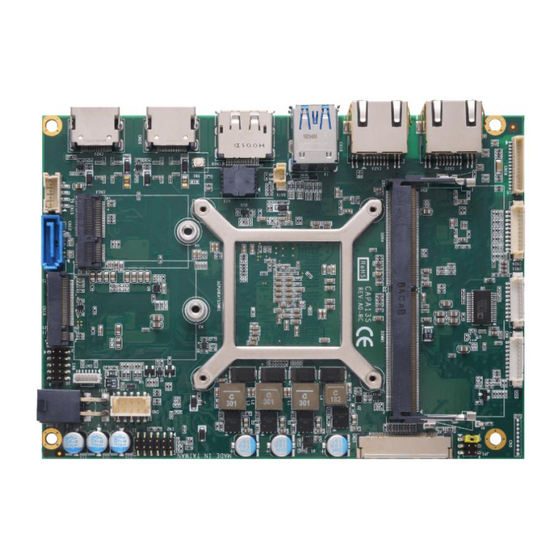
Page 11: Board And Pin Assignments
CAPA13S Capa Board Section 2 Board and Pin Assignments Board Dimensions and Fixing Holes Top View Board and Pin Assignments... - Page 12 CAPA13S Capa Board Bottom View Side View Board and Pin Assignments...
-
Page 13: Board Layout
CAPA13S Capa Board Board Layout Top View Rear I/O Board and Pin Assignments... - Page 14 CAPA13S Capa Board Bottom View Board and Pin Assignments...
-
Page 15: Installing Cooling Fan
CAPA13S Capa Board Installing Cooling Fan Image below illustrates how to install cooling fan on CAPA13S. Board and Pin Assignments... -
Page 16: Jumper And Switch Settings
And remove jumper clip from 2 jumper pins to open. Below illustration shows how to set up jumper. Properly configure jumper and switch settings on the CAPA13S to meet your application purpose. Below you can find a summary table of jumper, switch and onboard default settings. -
Page 17: Edp Voltage Selection (Jp1)
CAPA13S Capa Board 2.4.1 eDP Voltage Selection (JP1) This is a 2x3-pin (pitch=2.0mm) jumper. The board supports voltage selection for embedded DisplayPort (eDP). Use JP1 to set eDP connector (CN25) pin 1~4 LCD_VCC to +3.3V, +5V or +12V. To prevent hardware damage, before connecting please make sure that input voltage of display is correct. -
Page 18: Connectors
CAPA13S Capa Board Connectors Signals go to other parts of the system through connectors. Loose or improper connection might cause problems, please make sure all connectors are properly and firmly connected. Here is a summary table of connectors on the hardware. -
Page 19: Front Panel Connector (Cn2)
CAPA13S Capa Board 2.5.1 Front Panel Connector (CN2) This is a 2x6-pin header (pitch=2.0mm) for front panel interface. 8 10 12 Signal Signal BUZZER- BUZZER+ PWR_PSON 9 11 PWRLED- PWRLED+ PWRSW- PWRSW+ HW RST- HW RST+ HDDLED- HDDLED+ Internal Buzzer Pin 1(-) and 2(+) connect the internal buzzer cable. -
Page 20: Sim Card Wafer Connector (Cn7)
CAPA13S Capa Board 2.5.3 SIM Card Wafer Connector (CN7) The CN7 is a 6-pin (pitch=1.0mm) wafer connector, which is compliant with JST B6B-PH-K-S, for SIM Card interface. AX93A19 is suggested to use for CN7 to have SIM card slot. In order to work properly, the SIM card must be used together with 3G/4G LTE module in M.2 Key B connector/CN10. -
Page 21: Com1 And Com2 Wafer Connectors (Cn9 And Cn11)
CAPA13S Capa Board 2.5.5 COM1 and COM2 Wafer Connectors (CN9 and CN11) These are 9-pin (pitch=1.25mm) connectors which are compliant with Molex 53047-0910. The pin assignments of RS-232/RS-422/RS-485 are listed in table below. If you need COM1 port to support RS-422 or RS-485, please refer to BIOS setting in section 4.4. -
Page 22: 2242/3042 Key B Connector (Cn10)
CAPA13S Capa Board 2.5.6 M.2 2242/3042 Key B Connector (CN10) The CN10 is a M.2 Key B connector. It is suggested to install the M.2 storage module via SATA with 22mm width and 42mm length or the M.2 cellular module via USB 2.0 with 30mm width and 42mm length. -
Page 23: Sata Connector (Cn12)
CAPA13S Capa Board 2.5.7 SATA Connector (CN12) This Serial Advanced Technology Attachment (Serial ATA or SATA) connector is for high-speed SATA interface. It is a computer bus interface for connecting to devices such as hard disk drive. Signal SATA_TXP0 SATA_TXN0... -
Page 24: 2230 Key E Connector (Cn13)
CAPA13S Capa Board 2.5.8 M.2 2230 Key E Connector (CN13) The CN13 is a M.2 2230 Key E connector. It is suggested to install the M.2 wireless module via PCIe x1 and USB 2.0 with 22mm width and 30mm length. -
Page 25: Sata Power Connector (Cn15)
CAPA13S Capa Board 2.5.9 SATA Power Connector (CN15) This is a 4-pin (pitch=2mm) wafer connector, which is compliant with JST B4B-PH-K-S, for SATA power interface. Signal +12V 2.5.10 Ethernet Wafer Connector (CN16) This is a wafer connector which is compliant with JST BM15B-SRSS-TB 15-pin (pitch=1.0mm) for Ethernet port 3 interface. -
Page 26: Usb 3.2 Port (Cn18)
CAPA13S Capa Board 2.5.11 USB 3.2 Port (CN18) The board comes with two Universal Serial Bus (compliant with USB 3.2 Gen 2 (10Gb/s)) ports on the rear I/O for installing USB peripherals such as keyboard, mouse, scanner, etc. Signal Signal... -
Page 27: Hdmi Connector (Cn20 And Cn21)
CAPA13S Capa Board 2.5.13 HDMI Connector (CN20 and CN21) The HDMI (High-Definition Multimedia Interface) is a compact digital interface which is capable of transmitting high-definition video and high-resolution audio over a single cable. The board comes with two HDMI connectors on the rear I/O. -
Page 28: Audio Connector (Cn24)
CAPA13S Capa Board 2.5.15 Audio Connector (CN24) This is a 10-pin (pitch=1.25mm) wafer connector, which is compliant with Molex 53047-1010, for audio interface. Signal Signal MIC_IN LINE_IN_L LINE_IN_R AUDIO_OUT_L AUDIO_OUT_R 2.5.16 eDP Connector (CN25) The eDP interface is available through 40-pin connector (CN25), which is compliant with IPEX-20143. -
Page 29: Atx Power Connector (Atx1)
CAPA13S Capa Board 2.5.17 ATX Power Connector (ATX1) Steady and sufficient power can be supplied to all components on the board by connecting the power connector. Please make sure all components and devices are properly installed before connecting the power connector. - Page 30 CAPA13S Capa Board This page is intentionally left blank. Board and Pin Assignments...
-
Page 31: Hardware Description
Make sure all correct settings are arranged for the installed microprocessor to prevent the CPU from damages. BIOS The CAPA13S uses AMI Plug and Play BIOS with a single 64Mbit SPI Flash. System Memory The CAPA13S supports one 260-pin DDR4 SO-DIMM socket. The memory module comes in sizes of 4GB, 8GB and 16GB. -
Page 32: I/O Port Address Map
CAPA13S Capa Board I/O Port Address Map Hardware Description... -
Page 33: Interrupt Controller (Irq) Map
CAPA13S Capa Board Interrupt Controller (IRQ) Map The interrupt controller (IRQ) mapping list is shown as follows: Hardware Description... - Page 34 CAPA13S Capa Board Hardware Description...
- Page 35 CAPA13S Capa Board Hardware Description...
- Page 36 CAPA13S Capa Board Hardware Description...
- Page 37 CAPA13S Capa Board Hardware Description...
- Page 38 CAPA13S Capa Board Hardware Description...
-
Page 39: Memory Map
CAPA13S Capa Board Memory Map The memory mapping list is shown as follows: Hardware Description... - Page 40 CAPA13S Capa Board This page is intentionally left blank. Hardware Description...
-
Page 41: Ami Bios Setup Utility
CAPA13S Capa Board Section 4 AMI BIOS Setup Utility The AMI UEFI BIOS provides users with a built-in setup program to modify basic system configuration. All configured parameters are stored in a flash chip to save the setup information whenever the power is turned off. This section provides users with detailed description about how to set up basic system configuration through the AMI BIOS setup utility. - Page 42 CAPA13S Capa Board Hot Keys Description → Left/Right The Left and Right <Arrow> keys allow you to select a setup screen. The Up and Down <Arrow> keys allow you to select a setup screen or Up/Down sub-screen. The Plus and Minus <Arrow> keys allow you to change the field value of a +−...
-
Page 43: Main Menu
CAPA13S Capa Board Main Menu When you first enter the setup utility, you will enter the Main setup screen. You can always return to the Main setup screen by selecting the Main tab. System Time/Date can be set up as described below. -
Page 44: Advanced Menu
CAPA13S Capa Board Advanced Menu The Advanced menu also allows users to set configuration of the CPU and other system devices. You can select any of the items in the left frame of the screen to go to the sub menus: ►... - Page 45 CAPA13S Capa Board ⚫ F81803 Super IO Configuration You can use this screen to select options for serial port configuration, and change the value of the selected option. A description of the selected item appears on the right side of the screen.
- Page 46 CAPA13S Capa Board ⚫ Serial Port 1 Configuration Serial Port Enable or disable serial port 1. The optimal setting for base I/O address is 3F8h and for interrupt request address is IRQ4. COM Port Type Use this item to set RS-232/422/485 communication mode.
- Page 47 CAPA13S Capa Board ⚫ Serial Port 2 Configuration Serial Port Enable or disable serial port 2. The optimal setting for base I/O address is 2F8h and for interrupt request address is IRQ3. AMI BIOS Setup Utility...
- Page 48 CAPA13S Capa Board ⚫ Hardware Monitor This screen monitors hardware health status. This screen displays the temperature of system and CPU, fan speed in RPM and system voltages (VBAT and +5V). Smart Fan Function Enable or disable Smart Fan control function. Once enabled, you will be able to go further for Smart Fan Mode Configuration, see image below.
- Page 49 CAPA13S Capa Board ⚫ NVMe Configuration (Optional) If M.2 NVMe card is installed in M.2 2242/3042 Key B Connector (CN10) (see section 2.5.8) with BOM option change, you will also need customized BIOS to show and enable NVMe Configuration. The following screen displays NVMe (Non-Volatile Memory Express) controller and drive information.
- Page 50 CAPA13S Capa Board ⚫ Trusted Computing You can use this screen for TPM (Trusted Platform Module) configuration. It also shows current TPM status information. Security Device Support Enable or disable BIOS support for security device. AMI BIOS Setup Utility...
- Page 51 CAPA13S Capa Board ⚫ CPU Configuration This screen shows the CPU Configuration. SVM Mode Enable or disable SVM (Secure Virtual Machine) mode. Once enabled, you will be able to install a virtual machine on your system. Core Performance Boost If enabled, the CPU can be boosted up to its maximum clock speed when needed.
- Page 52 CAPA13S Capa Board ⚫ SATA Configuration During system boot up, BIOS automatically detects the presence of SATA devices. In the SATA Configuration menu, you can see the hardware currently installed in SATA ports. ⚫ USB Configuration USB Devices Display all detected USB devices.
- Page 53 CAPA13S Capa Board ⚫ Onboard Device Configuration. A description of the selected item appears on the right side of the screen. For items marked with “”, please press <Enter> for more options. Onboard Device Configuration Use this option to configure onboard device (e.g., Digital I/O setting).
- Page 54 CAPA13S Capa Board DIO Modification Enable or disable digital I/O modification. The default is Disabled. DIO port 0-7 Select this option to open DIO status sub-screen. If DIO Modification is disabled, you are not allowed to change inputs/outputs setting. The...
- Page 55 CAPA13S Capa Board If DIO Modification is enabled, you can load manufacture default and access to the DIO status sub-screen to change input/output setting, see image below. The DIO status sub-screen is as follows: AMI BIOS Setup Utility...
-
Page 56: Chipset Menu
CAPA13S Capa Board Chipset Menu The Chipset menu allows users to change the advanced chipset settings. You can select any of the items in the left frame of the screen to go to the sub menus: ► North Bridge For items marked with “”, please press <Enter> for more options. - Page 57 CAPA13S Capa Board ⚫ North Bridge This screen shows system memory information. AMI BIOS Setup Utility...
-
Page 58: Security Menu
CAPA13S Capa Board Security Menu The Security menu allows users to change the security settings for the system. ⚫ Administrator Password. Set administrator password. ⚫ User Password Set user password. AMI BIOS Setup Utility... -
Page 59: Boot Menu
CAPA13S Capa Board Boot Menu The Boot menu allows users to change boot options of the system. ⚫ Setup Prompt Timeout Number of seconds to wait for setup activation key. 65535(0xFFFF) means indefinite waiting. ⚫ Bootup NumLock State Use this item to select the power-on state for the keyboard NumLock. -
Page 60: Save & Exit Menu
CAPA13S Capa Board Save & Exit Menu The Save & Exit menu allows users to load your system configuration with optimal or fail-safe default values. ⚫ Save Changes and Exit When you have completed the system configuration changes, select this option to leave Setup and return to Main Menu. - Page 61 CAPA13S Capa Board ⚫ Discard Changes Select this option to quit Setup without making any permanent changes to the system configuration. Select Discard Changes from the Save & Exit menu and press <Enter>. Select Yes to discard changes. ⚫ Restore Defaults It automatically sets all Setup options to a complete set of default settings when you select this option.
- Page 62 CAPA13S Capa Board This page is intentionally left blank. AMI BIOS Setup Utility...
-
Page 63: Appendix A Watchdog Timer
CAPA13S Capa Board Appendix A Watchdog Timer A.1 About Watchdog Timer Software stability is major issue in most application. Some embedded systems are not watched by operator for 24 hours. It is usually too slow to wait for someone to reboot when computer hangs. -
Page 64: A.3 Sample Program
CAPA13S Capa Board A.3 Sample Program Assembly sample code : ;Enable WDT: dx,2Eh al,87 ;Un-lock super I/O dx,al dx,al ;Select Logic device: dx,2Eh al,07h dx,al dx,2Fh al,07h dx,al ;Enable WDT base address: dx,2Eh al,30h dx,al dx,2Fh al,01h dx,al ;Activate WDT:... - Page 65 CAPA13S Capa Board If N=79h, the time base is set to minute. M = time value 00: Time-out disable 01: Time-out occurs after 1 minute 02: Time-out occurs after 2 minutes 03: Time-out occurs after 3 minutes FFh: Time-out occurs after 255 minutes...
- Page 66 CAPA13S Capa Board This page is intentionally left blank. Watchdog Timer...
-
Page 67: Appendix B Digital I/O
CAPA13S Capa Board Appendix B Digital I/O B.1 About Digital I/O The onboard GPIO or digital I/O has 8 bits. Each bit can be set to function as input or output by software programming. In default, all pins are pulled high with +5V level (according to main power). - Page 68 CAPA13S Capa Board Register 0: Input port register. This register is a read-only port. It reflects the incoming logic levels of the pins, regardless of whether the pin is defined as an input or an output by Register 3. Writes to this register have no effect.
- Page 69 CAPA13S Capa Board Register 3: Configuration register. This register configures the directions of the I/O pins. If a bit in this register is set, the corresponding port pin is enabled as an input with high-impedance output driver. If a bit in this register is cleared, the corresponding port pin is enabled as an output.
Need help?
Do you have a question about the CAPA13S and is the answer not in the manual?
Questions and answers