AXIOMTEK CEM521 User Manual
8th generation intel core i7/i5/i3 and celeron processors com express type 6 compact module
Hide thumbs
Also See for CEM521:
- Quick installation manual (2 pages) ,
- Quick installation manual (2 pages)

Related Manuals for AXIOMTEK CEM521


Summary of Contents for AXIOMTEK CEM521
- Page 1 CEM521 ® Generation Intel Core i7/i5/i3 and Celeron processors COM Express Type 6 Compact Module User’s Manual...
- Page 2 Axiomtek does not make any commitment to update the information in this manual. Axiomtek reserves the right to change or revise this document and/or product at any time without notice. No part of this document may be reproduced, stored in a retrieval system, or transmitted, in any form or by any means, electronic, mechanical, photocopying, recording, or otherwise, without the prior written permission of Axiomtek Co., Ltd.
-
Page 3: Esd Precautions
Wear a wrist-grounding strap, available from most electronic component stores, when handling modules and components. Trademarks Acknowledgments Axiomtek is a trademark of Axiomtek Co., Ltd. ® Windows is a trademark of Microsoft Corporation. AMI is a trademark of American Megatrend Inc. -
Page 4: Table Of Contents
Table of Contents Disclaimers ..................... ii ESD Precautions ................... iii Chapter 1 Introduction ..........1 Features ....................1 Specifications ..................2 Utilities Supported ................3 Chapter 2 Module and Pin Assignments ....5 Module Dimensions and Fixing Holes ..........5 Module Layout .................. - Page 5 Save & Exit Menu ................52 Appendix A Watchdog Timer ........55 About Watchdog Timer ..............55 How to Use Watchdog Timer ............55 Appendix B Digital I/O ..........57 About Digital I/O ................57 How to Use Digital I/O ............... 57 Appendix C iAMT Settings ........
- Page 6 This page is intentionally left blank.
-
Page 7: Chapter 1 Introduction
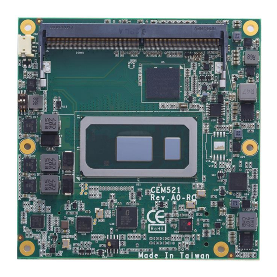
CEM521 COM Express Type 6 Module Chapter 1 Introduction ® Core™ The CEM521 is a new COM Express Type 6 Compact Module supporting Intel ® ® i7-8665UE/i5-8365UE/i3-8145UE processor and Intel Celeron processor 4305UE. It delivers outstanding system performance and support excellent multiple I/Os like LVDS, one Gigabit Ethernet, HD Audio interface, three SATA-600, four USB 3.0 and eight USB 2.0 ports. -
Page 8: Specifications
CEM521 COM Express Type 6 Module Specifications ® Core™ i7-8665UE. Intel ® Core™ i5-8365UE. Intel ® Core™ i3-8145UE. Intel ® ® Intel Celeron 4305UE. BIOS American Megatrends Inc. BIOS. UEFI Legacy Free. -
Page 9: Utilities Supported
CEM521 COM Express Type 6 Module Power Management ACPI (Advanced Configuration and Power Interface). Form Factor Compact module 95mm x 95mm. Utilities Supported Chipset driver Graphics driver Serial Patch_v3.0.6.7MS Rapid Storage Technology ... - Page 10 CEM521 COM Express Type 6 Module This page is intentionally left blank. Introduction...
-
Page 11: Module And Pin Assignments
CEM521 COM Express Type 6 Module Chapter 2 Module and Pin Assignments Module Dimensions and Fixing Holes Top View Module and Pin Assignments... -
Page 12: Module Layout
CEM521 COM Express Type 6 Module Module Layout Top View Module and Pin Assignments... - Page 13 CEM521 COM Express Type 6 Module Bottom View Module and Pin Assignments...
-
Page 14: Installing Thermal Solution
This CPU module has six assembly holes for installing heatsink plate. Use the six screws to secure the heatsink plate to the CEM521. Be careful not to over-tighten the screws. Module and Pin Assignments... - Page 15 CEM521 COM Express Type 6 Module When installing CEM521 on CEB94011, please add stand-off and secure with nut. Then, use the screws to secure the heatsink plate to the CEM521. Note Module and Pin Assignments...
-
Page 16: Switch Settings
Type 6 Module Switch Settings Properly configure switch settings on the CEM521 to meet your application purpose. Below you can find a summary table of switch and onboard default setting. Once the default switch setting needs to be changed, please do it under power-off condition. -
Page 17: Connector
CEM521 COM Express Type 6 Module Connector Signals go to the other parts of the system through connectors. Loose or improper connection might cause problems, please make sure all connectors are properly and firmly connected. Here is a summary table which shows connectors on the hardware. -
Page 18: Com Express Tm Connector (Ss1 And Ss2)
CEM521 COM Express Type 6 Module 2.5.3 COM Express Connector (SS1 and SS2) The following table shows pin assignments of the 220-pin COM Express connectors. Bottom View Module and Pin Assignments... - Page 19 CEM521 COM Express Type 6 Module Signal Signal Signal Signal GND (FIXED) GND (FIXED) GND (FIXED) GND (FIXED) LAN1_MDI3- LAN1_LED_ACT_N LAN1_MDI3+ LPC_FRAME_N USB3_RX0_N USB3_TX0_N LAN1_LED_100_N LPC_AD0 USB3_RX0_P USB3_TX0_P LAN1_LED_1000_N B5 LPC_AD1 LAN1_MDI2- LPC_AD2 USB3_RX1_N USB3_TX1_N LAN1_MDI2+ LPC_AD3 USB3_RX1_P USB3_TX1_P LAN1_LINK_LED_N B8 N.C.
- Page 20 CEM521 COM Express Type 6 Module Signal Signal Signal Pin Signal PCIE_TX_DN4 PCIE_RX_DN4 N.C. N.C. COM_GPO2 N.C. TYPE2_N PCIE_TX_DP3 PCIE_RX_DP3 N.C. N.C. PCIE_TX_DN3 PCIE_RX_DN3 N.C. N.C. GND (FIXED) GND (FIXED) GND (FIXED) GND (FIXED) PCIE_TX_DP2 PCIE_RX_DP2 N.C. N.C. PCIE_TX_DN2 PCIE_RX_DN2 N.C.
-
Page 21: Chapter 3 Hardware Description
You must install the heatsink or cooler carefully and properly to prevent damage. BIOS The CEM521 uses AMI Plug and Play BIOS with a single 256Mbit SPI Flash. System Memory The CEM521 supports two 260-pin DDR4 2400MHz SO-DIMM sockets for maximum memory capacity up to 64GB DDR4 SDRAMs. -
Page 22: I/O Port Address Map
CEM521 COM Express Type 6 Module I/O Port Address Map Hardware Description... -
Page 23: Interrupt Controller (Irq) Map
CEM521 COM Express Type 6 Module Interrupt Controller (IRQ) Map The interrupt controller (IRQ) mapping list is shown as follows: Hardware Description... - Page 24 CEM521 COM Express Type 6 Module Hardware Description...
- Page 25 CEM521 COM Express Type 6 Module Hardware Description...
- Page 26 CEM521 COM Express Type 6 Module Hardware Description...
- Page 27 CEM521 COM Express Type 6 Module Hardware Description...
-
Page 28: Memory Map
CEM521 COM Express Type 6 Module Memory Map The memory mapping list is shown as follows: Hardware Description... -
Page 29: Ami Bios Setup Utility
CEM521 COM Express Type 6 Module Chapter 4 AMI BIOS Setup Utility The AMI UEFI BIOS provides users with a built-in setup program to modify basic system configuration. All configured parameters are stored in a flash chip to save the setup information whenever the power is turned off. - Page 30 CEM521 COM Express Type 6 Module Hot Keys Description Left/Right The Left and Right <Arrow> keys allow you to select a setup screen. The Up and Down <Arrow> keys allow you to select a setup screen or sub Up/Down screen.
-
Page 31: Main Menu
CEM521 COM Express Type 6 Module Main Menu When you first enter the setup utility, you will enter the Main setup screen. You can always return to the Main setup screen by selecting the Main tab. System Time/Date can be set up as described below. -
Page 32: Advanced Menu
CEM521 COM Express Type 6 Module Advanced Menu The Advanced menu also allows users to set configuration of the CPU and other system devices. You can select any of the items in the left frame of the screen to go to the sub menus: ►... - Page 33 CEM521 COM Express Type 6 Module Ec DIO Configuration You can use this screen to select options for DIO configuration. A description of selected item appears on the right side of the screen. For more details, see Appendix B.
- Page 34 CEM521 COM Express Type 6 Module If DIO Modification is enabled, you can load manufacture default and access to the DIO status sub screen to change inputs/outputs setting, see images below. AMI BIOS Setup Utility...
- Page 35 CEM521 COM Express Type 6 Module Serial Port Configuration You can use this screen to select options for Serial Port Configuration, and change the value of the selected option. A description of the selected item appears on the right side of the screen.
- Page 36 CEM521 COM Express Type 6 Module Serial Port 1 (UART1) Serial Port Enable or disable serial port 1. The optimal setting for base I/O address is 248h and for interrupt request address is IRQ7. Serial Port 2 (UART2) Serial Port Enable or disable serial port 2.
- Page 37 CEM521 COM Express Type 6 Module Hardware Monitor This screen is for fan speed control and hardware health status monitoring. This screen displays the temperature of system and CPU, cooling fans speed in RPM and system voltages (+3.3V, +3.3V standby and +5V).
- Page 38 CEM521 COM Express Type 6 Module CEMSIO Serial IO Configuration You can use this screen to select options for CEMSIO Serial IO Configuration, and change the value of the selected option. A description of the selected item appears on the right side of the screen.
- Page 39 CEM521 COM Express Type 6 Module Serial Port 3 Configuration Serial Port Enable or disable serial port 3. The optimal setting for base I/O address is 3F8h and for interrupt request address is IRQ4. COM Port Type Use this item to set RS-232/422/485 communication mode.
- Page 40 CEM521 COM Express Type 6 Module Serial Port 4 Configuration Serial Port Enable or disable serial port 4. The optimal setting for base I/O address is 2F8h and for interrupt request address is IRQ3. COM Port Type Use this item to set RS-232/422/485 communication mode.
- Page 41 CEM521 COM Express Type 6 Module ACPI Settings You can use this screen to select options for the ACPI configuration, and change the value of the selected option. A description of the selected item appears on the right side of the screen.
- Page 42 CEM521 COM Express Type 6 Module Trusted Computing You can use this screen for TPM (Trusted Platform Module) configuration. It also shows current TPM status information. Security Device Support Enable or disable BIOS support for security device. AMI BIOS Setup Utility...
- Page 43 CEM521 COM Express Type 6 Module CPU Configuration This screen shows the CPU Configuration, and you can change the value of the selected option. Intel Virtualization Technology Enable or disable Intel Virtualization Technology. When enabled, a VMM (Virtual Machine Mode) can utilize the additional hardware capabilities.
- Page 44 CEM521 COM Express Type 6 Module SATA Configuration In the SATA Configuration menu, you can see the currently installed hardware in the SATA ports. During system boot up, the BIOS automatically detects the presence of SATA devices. SATA Controller(s) Enable or disable the SATA Controller feature.
- Page 45 CEM521 COM Express Type 6 Module PCH-FW Configuration This screen displays ME Firmware information. AMT Configuration Use this screen to configure AMT parameters. AMT BIOS Features When disabled, AMI BIOS Features are no longer supported and user is no longer able to access MEBx Setup.
- Page 46 CEM521 COM Express Type 6 Module USB Configuration USB Devices Display all detected USB devices. AMI BIOS Setup Utility...
- Page 47 CEM521 COM Express Type 6 Module Serial Port Console Redirection You can use this screen to select options for Serial Port Console Redirection, and change the value of the selected option. A description of the selected item appears on the right side of the screen.
- Page 48 CEM521 COM Express Type 6 Module Console Redirection Settings AMI BIOS Setup Utility...
-
Page 49: Chipset Menu
CEM521 COM Express Type 6 Module Chipset Menu The Chipset menu allows users to change the advanced chipset settings. You can select any of the items in the left frame of the screen to go to the sub menus: ►... - Page 50 CEM521 COM Express Type 6 Module System Agent (SA) Configuration This screen shows System Agent version information and provides function for specifying related parameters. Graphics Configuration Open sub menu for parameters related to graphics configuration. Memory Configuration Open sub menu for information related to system memory.
- Page 51 CEM521 COM Express Type 6 Module Graphics Configuration DDI1 Signal Select Select the DDI1 signal output to DisplayPort or HDMI. DDI2 Signal Select Select the DDI2 signal output to DisplayPort or HDMI. AMI BIOS Setup Utility...
- Page 52 CEM521 COM Express Type 6 Module LCD Control LVDS Panel Type After LVDS Panel Device is enabled, the LVDS Panel Type is showed for selection. Select the appropriate LVDS panel resolution by options in image above. Memory Configuration This screen shows the system memory information.
- Page 53 CEM521 COM Express Type 6 Module PCH-IO Configuration This screen shows PCH-IO information. PCH LAN Controller Enable or disable onboard PCH LAN controller. Wake on LAN Enable Enable or disable integrated LAN to wake the system. AMI BIOS Setup Utility...
- Page 54 CEM521 COM Express Type 6 Module eMMC 5.1 Controller Enable or disable SCS eMMC 5.0 Controller. MMC – DG4032(31.2GB) Mass storage device emulation type. Auto: Enumerates devices less than 530MB as floppies. Forced FDD: Can be used to force HDD formatted drive to boot as FDD.
-
Page 55: Security Menu
CEM521 COM Express Type 6 Module Security Menu The Security menu allows users to change the security settings for the system. Administrator Password. Set administrator password. User Password Set user password. AMI BIOS Setup Utility... -
Page 56: Boot Menu
CEM521 COM Express Type 6 Module Boot Menu The Boot menu allows users to change boot options of the system. Setup Prompt Timeout Number of seconds to wait for setup activation key. 65535(0xFFFF) means indefinite waiting. Bootup NumLock State Use this item to select the power-on state for the keyboard NumLock. - Page 57 CEM521 COM Express Type 6 Module Boot Mode Use this option for boot mode settings. UEFI Boot: Select support to boot any UEFI-capable OS. Legacy Boot: Select support to boot non UEFI-capable OS that expects a legacy BIOS interface.
-
Page 58: Save & Exit Menu
CEM521 COM Express Type 6 Module Save & Exit Menu The Save & Exit menu allows users to load your system configuration with optimal or fail-safe default values. Save Changes and Exit When you have completed the system configuration changes, select this option to leave Setup and return to Main Menu. - Page 59 CEM521 COM Express Type 6 Module Discard Changes Select this option to quit Setup without making any permanent changes to the system configuration. Select Discard Changes from the Save & Exit menu and press <Enter>. Select Yes to discard changes.
- Page 60 CEM521 COM Express Type 6 Module This page is intentionally left blank. AMI BIOS Setup Utility...
-
Page 61: Appendix A Watchdog Timer
CEM521 COM Express Type 6 Module Appendix A Watchdog Timer A.1 About Watchdog Timer After the system stops working for a while, it can be auto-reset by the watchdog timer. The integrated watchdog timer can be set up in the system reset mode by program. - Page 62 CEM521 COM Express Type 6 Module This page is intentionally left blank. Watchdog Timer...
-
Page 63: Appendix B Digital I/O
CEM521 COM Express Type 6 Module Appendix B Digital I/O B.1 About Digital I/O The onboard GPIO or digital I/O has 8 bits (DIO0~7). Each bit can be set to function as input or output by software programming. In default, all pins are pulled high with +3.3V level (according to main power). - Page 64 CEM521 COM Express Type 6 Module // Set DIO High/Low,1:High,0:Low,now is set to BIT0-BIT3 is Low,BIT4-BIT7 is // High outportb(AXIOM_DIO_HIGH_LOW_ADDR, DIO_DefaultHighLowSetting); printf("DIO High/Low set to 0x%X \n", DIO_DefaultHighLowSetting); printf("BIT0-BIT3 is set to input so do not care,BIT4-BIT7 is setting to High");...
-
Page 65: Appendix C Iamt Settings
CEM521 COM Express Type 6 Module Appendix C iAMT Settings ® ® The Intel Active Management Technology (Intel iAMT) has decreased a major barrier to IT efficiency that uses built-in platform capabilities and popular third-party management and security applications to allow IT a better discovering, healing, and protection their networked computing assets. - Page 66 CEM521 COM Express Type 6 Module You will be asked to change the password before setting ME. You must confirm your new password while revising. The new password must contain: (example: !!11qqQQ) (default value). Eight characters One upper case ...
- Page 67 CEM521 COM Express Type 6 Module From Main Menu, select ME General Settings to get into ME Platform Configuration screen. In this screen you can modify Local FW Update setting. Return to Main Menu. iAMT Settings...
-
Page 68: Iamt Settings
CEM521 COM Express Type 6 Module iAMT Settings ® Select Intel AMT configuration and press <Enter>. From AMT Configuration menu, select Manageability Feature Selection and set it to Enabled. ® This item allows you to enable or disable Intel AMT feature. - Page 69 CEM521 COM Express Type 6 Module Network Setup 1. Select Network Setup to configure iAMT. 2. Select ME Network Name Settings to set computer host and domain name. iAMT Settings...
- Page 70 CEM521 COM Express Type 6 Module 3. Select TCP/IP to get into Network interface and set it to Enabled. Get into DHCP Mode and set it to Disabled. iAMT Settings...
- Page 71 CEM521 COM Express Type 6 Module 4. If DHCP Mode is disabled, set the following settings: IP address Subnet mask iAMT Settings...
- Page 72 CEM521 COM Express Type 6 Module ® 5. Go back to Intel iAMT Configuration, then select Activate Network Access and press <Enter>. 6. Exit from MEBx after completing the iAMT settings. iAMT Settings...
-
Page 73: Iamt Web Console
CEM521 COM Express Type 6 Module iAMT Web Console From a web browser, please type http://(IP ADDRESS):16992, which connects to iAMT Web. Example: http://10.1.40.214:16992 To log on, you will be required to type in username and password for access to the Web. - Page 74 CEM521 COM Express Type 6 Module Enter the iAMT Web. iAMT Settings...
- Page 75 CEM521 COM Express Type 6 Module Click Remote Control, and select commands on the right side. When you have finished using the iAMT Web console, close the Web browser. iAMT Settings...
Need help?
Do you have a question about the CEM521 and is the answer not in the manual?
Questions and answers