Table of Contents
Advertisement
Quick Links
Advertisement
Table of Contents

Related Manuals for AXIOMTEK CEB94022


Summary of Contents for AXIOMTEK CEB94022
- Page 1 CEB94022 COM Express Type 6 with MXM Application Board User’s Manual...
- Page 2 Axiomtek does not make any commitment to update the information in this manual. Axiomtek reserves the right to change or revise this document and/or product at any time without notice. No part of this document may be reproduced, stored in a retrieval system, or transmitted, in any form or by any means, electronic, mechanical, photocopying, recording, or otherwise, without the prior written permission of Axiomtek Co., Ltd.
-
Page 3: Esd Precautions
It discharges static electricity from your body. Wear a wrist-grounding strap, available from most electronic component stores, when handling boards and components. Trademarks Acknowledgments Axiomtek is a trademark of Axiomtek Co., Ltd. ® ® Intel and Celeron are trademarks of Intel Corporation. -
Page 4: Table Of Contents
Table of Contents Disclaimers ..................... ii ESD Precautions ................... iii Chapter 1 Introduction ..........1 Features ....................2 Specifications ..................2 Utilities Supported ................3 Chapter 2 Board and Pin Assignments ....5 Board Dimensions and Fixing Holes ..........5 Board Layout .................. - Page 5 Buttons ....................30 LED Indicators ................... 30 Chapter 3 AMI BIOS ..........31 Starting ....................31 Main Menu ..................32 Advanced Menu ................. 33 Chipset Menu ..................42...
- Page 6 This page is intentionally left blank.
-
Page 7: Chapter 1 Introduction
Type 6 with MXM slot which fully compliant with the PCI Industrial Computer Manufactures PICMG COM Express standard. In addition to the standard output signals for converting, CEB94022 provides six display interfaces which include one HDMI port (from COM Express module), one DP port (from COM Express module) and four DP port (from MXM module). -
Page 8: Features
CEB94022 COM Express Type 6 with MXM Application Board Features 1 HDMI and 1 DP ports (default from COM Express module) 4 DP ports (from MXM module) MXM Type A support 2 Gigabit LAN ports ... -
Page 9: Utilities Supported
CEB94022 COM Express Type 6 with MXM Application Board Digital I/O Four inputs and four outputs in wafer connector. Display One 2x20-pin connector for 18/24-bit single/dual channel LVDS and one 8-pin inverter connector. LVDS resolution is up to 1920x1200 in 24-bit dual channels. - Page 10 CEB94022 COM Express Type 6 with MXM Application Board This page is intentionally left blank. Introduction...
-
Page 11: Board And Pin Assignments
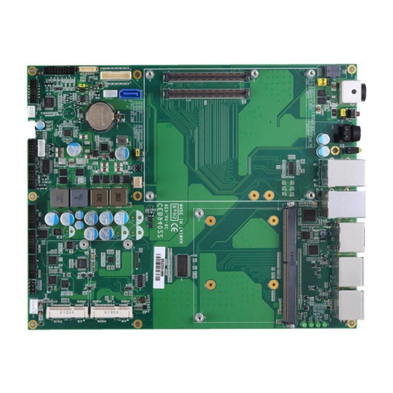
CEB94022 COM Express Type 6 with MXM Application Board Chapter 2 Board and Pin Assignments Board Dimensions and Fixing Holes Top View Board and Pin Assignments... - Page 12 CEB94022 COM Express Type 6 with MXM Application Board Bottom View Side View Board and Pin Assignments...
-
Page 13: Board Layout
CEB94022 COM Express Type 6 with MXM Application Board Board Layout Top View Board and Pin Assignments... -
Page 14: Assembly Drawing
CEB94022 COM Express Type 6 with MXM Application Board Assembly Drawing The CEB94022 has some assembly holes for installation. Align and firmly install the basic size CEM Express module on CEB94022 as indicated in image below. Board and Pin Assignments... -
Page 15: Jumper Settings
And remove jumper clip from 2 jumper pins to open. Below illustration shows how to set up jumper. Properly configure jumper settings on the CEB94022 to meet your application purpose. Below you can find a summary table of all jumpers and onboard default settings. -
Page 16: Lvds Voltage Selection (Jp1)
CEB94022 COM Express Type 6 with MXM Application Board 2.4.1 LVDS Voltage Selection (JP1) The board supports voltage selection for flat panel displays. Use this jumper to set LVDS connector (CN16) pin 1~6 VCCM to +3.3V, +5V or +12V. To prevent hardware damage, before connecting please make sure that the input voltage of flat panel is correct. -
Page 17: Connectors
CEB94022 COM Express Type 6 with MXM Application Board Connectors Signals go to other parts of the system through connectors. Loose or improper connection might cause problems, please make sure all connectors are properly and firmly connected. Here is a summary table which shows all connectors on the hardware. -
Page 18: C Connector (Cn1)
CEB94022 COM Express Type 6 with MXM Application Board 2.5.1 C Connector (CN1) This is a 3-pin (pitch=2.0mm) connector. The I C interface is a simple bus for the purpose of lightweight communication. Signal I2C_CLK I2C_DATA 2.5.2 USB 2.0 Wafer Connector (CN2) The CN2 (for USB port 4 and 5) is a 2x5-pin (pitch=2.0mm) connector commonly used... -
Page 19: Front Panel Connector (Cn3)
CEB94022 COM Express Type 6 with MXM Application Board 2.5.3 Front Panel Connector (CN3) This is a 2x4-pin (pitch=2.54mm) connector for front panel interface. Signal Signal PWRSW- PWRSW+- HW RST- HW RST+ PWRLED- PWRLED+ HDDLED- HDDLED+ Power On/Off Button Pin 1 and 2 connect the power button on front panel to CPU board, which allows users to turn on or off power supply. -
Page 20: Com Connectors (Cn5~Cn8)
CEB94022 COM Express Type 6 with MXM Application Board 2.5.5 COM Connectors (CN5~CN8) These are Molex 78046-102, 2x5-pin (pitch=2.0mm) box headers for serial port interfaces. The COM3~COM5 support RS-232/422/485 communication mode, while the COM6 supports RS-232 only. The related pin assignments are given in table below. You can change the communication mode in BIOS Setup utility. -
Page 21: Vga Wafer Connector (Cn11)
CEB94022 COM Express Type 6 with MXM Application Board 2.5.8 VGA Wafer Connector (CN11) This is a 2x8-pin (pitch=2.0mm) connector for VGA interface. Signal Signal GREEN N.C. BLUE DDC DATA HSYNC VSYNC DDC CLK N.C. 2.5.9 PCI-Express Mini Card Connectors (CN12 and CN15) These are full-size PCI-Express Mini Card connectors complying with PCI-Express Mini Card Spec. -
Page 22: Inverter Connector (Cn13)
CEB94022 COM Express Type 6 with MXM Application Board 2.5.10 Inverter Connector (CN13) This is a 8-pin (pitch=1.25mm) connector for inverter. We strongly recommend you to use the matching DF13-8P-1.25C connector to avoid malfunction. Signal VBL1 (+12V level) VBL1 (+12V level) -
Page 23: Lvds Connector (Cn16)
CEB94022 COM Express Type 6 with MXM Application Board 2.5.12 LVDS Connector (CN16) The board has one 2x20-pin (pitch=1mm) connector for LVDS LCD interface. It is strongly recommended to use the matching JST SHDR-40VS-B connector for LVDS interface. Pin 1~6 VCCM can be set to +3.3V, +5V or +12V by setting JP1 (see section 2.4.1). - Page 24 CEB94022 COM Express Type 6 with MXM Application Board 24-bit single channel 18-bit dual channel Pin Signal Pin Signal Pin Signal Pin Signal VCCM VCCM VCCM VCCM VCCM VCCM VCCM VCCM VCCM VCCM VCCM VCCM EDID DATA EDID CLK EDID DATA...
-
Page 25: Sata Connector (Cn17)
CEB94022 COM Express Type 6 with MXM Application Board 2.5.13 SATA Connector (CN17) The CN17 is a connector for high-speed Serial Advanced Technology Attachment (Serial ATA or SATA) interface. It is a computer bus interface for connecting to devices such as hard disk drive. -
Page 26: Lan And Usb 3.0 Port (Cn19)
CEB94022 COM Express Type 6 with MXM Application Board 2.5.14 LAN and USB 3.0 Port (CN19) The board comes with high performance plug and play Ethernet interface (RJ-45) which is fully compliant with the IEEE 802.3 standard. Connection can be established by plugging one end of the Ethernet cable into this RJ-45 connector and the other end to a 1000/100/10 Base-T hub. -
Page 27: Lan And Usb 2.0 Port (Cn20)
CEB94022 COM Express Type 6 with MXM Application Board 2.5.15 LAN and USB 2.0 Port (CN20) The board comes with high performance plug and play Ethernet interface (RJ-45) which is fully compliant with the IEEE 802.3 standard. Connection can be established by plugging one end of the Ethernet cable into this RJ-45 connector and the other end to a 1000/100/10 Base-T hub. -
Page 28: Displayport And Hdmi Connector (Cn22)
CEB94022 COM Express Type 6 with MXM Application Board 2.5.16 DisplayPort and HDMI Connector (CN22) The CN22 is a double-deck connector comprising an upper connector for DisplayPort interface and a lower connector for HDMI interface. Signal Signal LANE 0 DATA2... -
Page 29: Displayport Combo Connectors (Dp1 And Dp2)
CEB94022 COM Express Type 6 with MXM Application Board 2.5.18 DisplayPort Combo Connectors (DP1 and DP2) The board comes with two DisplayPort combo connectors (DP1 and DP2). DP1: DP1 Signal DP1 Signal LANE1_0 LANE2_0 LANE1_0# LANE2_0# LANE1_1 LANE2_1 LANE1_1# LANE2_1#... -
Page 30: Fan Connectors (Fan1 And Fan3)
CEB94022 COM Express Type 6 with MXM Application Board 2.5.19 Fan Connectors (FAN1 and FAN3) Fans are needed for cooling down temperature. You can find fan speed option(s) within BIOS Setup Utility. For further information, see BIOS Setup Utility: Advanced\Hardware Monitor\PC Health Status. -
Page 31: Mxm Type A Connector (Mxm1)
CEB94022 COM Express Type 6 with MXM Application Board 2.5.20 MXM Type A Connector (MXM1) The MXM1 is a 285-pin connector for connecting MXM module and COM Express baseboard. The pin assignments are as follows. Signal Signal Signal Signal PWR_SRC... - Page 32 CEB94022 COM Express Type 6 with MXM Application Board Signal Signal Signal Signal CLK_REQ# RSVD DP_D_AUX# PCIE_CLK# PCIE_RST# RSVD DP_D_AUX PCIE_CLK RSVD HPD_C RSVD HPD_D RSVD RSVD RSVD RSVD RSVD DP_B_0# RSVD DP_B_0 RSVD RSVD DP_B_1# DP_B_1 DP_A_0# DP_A_0 DP_B_2#...
-
Page 33: Com Express Tm Connectors (Recs1 And Recs2)
CEB94022 COM Express Type 6 with MXM Application Board 2.5.21 COM Express Connectors (RECS1 and RECS2) The RECS1 and RECS2 are 220-pin connectors for connecting COM Express module and COM Express baseboard. The pin assignments are as follows. RECS1 RECS2... - Page 34 CEB94022 COM Express Type 6 with MXM Application Board Signal Signal Signal Signal GND (FIXED) GND (FIXED) GND (FIXED) GND (FIXED) GBE0_MDI3- GBE0_ACT# GND (FIXED) GND (FIXED) GBE0_MDI3+ LPC_FRAME# USB_SSRX0- USB_SSTX0- GBE0_LINK100# LPC_AD0 USB_SSRX0+ USB_SSTX0+ GBE0_LINK1000# LPC_AD1 GND (FIXED) GND (FIXED)
- Page 35 CEB94022 COM Express Type 6 with MXM Application Board Signal Signal Signal Signal PEG_RX1- PEG_TX1- GPO2 TYPE2# PEG_RX2+ PEG_TX2+ PEG_RX2- PEG_TX2- GND (FIXED) GND (FIXED) GND (FIXED) GND (FIXED) PCIE_TX2+ PCIE_RX2+ PEG_RX3+ PEG_TX3+ PCIE_TX2- PCIE_RX2- PEG_RX3- PEG_TX3- GPI1 GPO3 RSVD...
-
Page 36: Buttons
CEB94022 COM Express Type 6 with MXM Application Board Buttons The board has two buttons, see table below. CN21 Button Description CN21 Power button for system power on CN24 Reset button CN24 LED Indicators The board comes with the following LEDs. See table below for detailed information. -
Page 37: Chapter 3 Ami Bios
Chapter 3 AMI BIOS The BIOS functions described in this chapter are available only when CEB94022 is connected to CPU module. For the other detailed description about how to set up basic system configuration through AMI BIOS setup utility, please refer to the CPU module user’s manual. -
Page 38: Main Menu
CEB94022 COM Express Type 6 with MXM Application Board Main Menu When you first enter the setup utility, you will enter the Main setup screen. You can always return to the Main setup screen by selecting the Main tab. System Time/Date can be set up as described below. -
Page 39: Advanced Menu
For items marked with “”, please press <Enter> for more options. The sub menus marked with red rectangular contain functions available only if CEB94022 is connected to CPU module. The functions are COM port settings in Super IO Configuration, an extra mSATA/PCIe selection in SATA Configuration and digital I/O settings in DIO Configuration. - Page 40 This screen monitors hardware health status. This screen displays the temperature of system and CPU, cooling fans speed in RPM and system voltages (VBAT, +3.3V, +3.3V standby and +5V). FAN1 is on CEB94022. FAN2 is on CEM Express module.
- Page 41 CEB94022 COM Express Type 6 with MXM Application Board CEMSIO Super IO Configuration You can use this screen to select options for Serial Port Configuration, and change the value of the selected option. A description of the selected item appears on the right side of the screen.
- Page 42 CEB94022 COM Express Type 6 with MXM Application Board Serial Port 3~6 Configuration Serial Port 3~6 Enable or disable serial port 3~6. The optimal settings for base I/O address and for interrupt request address are: Serial port 3: 3F8h, IRQ4...
- Page 43 CEB94022 COM Express Type 6 with MXM Application Board SATA And RST Configuration During system boot up, BIOS automatically detects the presence of SATA devices. In this Configuration menu, you can see the currently installed hardware in SATA ports.
- Page 44 CEB94022 COM Express Type 6 with MXM Application Board Device Configuration A description of selected item appears on the right side of the screen. For items marked with “”, please press <Enter> for more options. Onboard Device Configuration Use this option to configure onboard device (e.g., DIO setting).
- Page 45 CEB94022 COM Express Type 6 with MXM Application Board Onboard DIO Configuration You can use this screen to select options for the 8-bit Digital I/O Configuration. A description of the selected item appears on the right side of the screen. For items marked with “”, please press <Enter>...
- Page 46 CEB94022 COM Express Type 6 with MXM Application Board Onboard DIO Configuration Use this screen to set parameters related to digital I/O configuration. DIO Modification Enable or disable digital I/O modification. The default is Disabled. DIO port 1-8 Select this option to open DIO status sub screen.
- Page 47 CEB94022 COM Express Type 6 with MXM Application Board If DIO Modification is enabled, you can load manufacture default and access to the DIO status sub screen to change input/output setting, see image below. The DIO status sub screen is as follows:...
-
Page 48: Chipset Menu
CEB94022 COM Express Type 6 with MXM Application Board Chipset Menu The Chipset menu allows users to change the advanced chipset settings. You can select any of the items in the left frame of the screen to go to the sub menus: ►... - Page 49 CEB94022 COM Express Type 6 with MXM Application Board System Agent (SA) Configuration This screen allows users to configure System Agent (SA) parameters. For items marked with “”, please press <Enter> for more options. Graphics Configuration Select to open sub menu for parameters related to graphics configuration.
- Page 50 DDI1 Signal Select Select the DDI1 signal (display output on CN22 upper side) to DisplayPort. This item must be set to DisplayPort if you want to enable DP port on CEB94022. DDI2 Signal Select Select the DDI2 signal (display output on CN22 lower side) to HDMI/DVI. This item must be set to HDMI/DVI if you want to enable HDMI port on CEB94022.
Need help?
Do you have a question about the CEB94022 and is the answer not in the manual?
Questions and answers