Advertisement
Quick Links
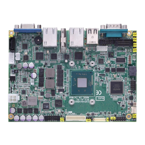
Side View
Quick Start
The basic procedures required to power on CAPA841/842:
(1). Require power at minimum 2.5A. Ensure that power supply is
OFF before connecting to CAPA841/842 and that all
necessary peripheral devices are plugged properly.
(2). Ensure all of the jumpers are at default settings; especially
JP10 (1-2 close).
(3). Firmly install DDR3L memory modules into connector
SSODIMM1 until fully seated.
Note: It must be DDR3L memory module.
(4). Firmly insert power to ATX1.
(5). Install a momentary on/off button/switch onto CN1, pin 9 and
10.
(6). Turn on the power supply.
(7). Press the on/off button/switch to power on CAPA841/842
4
9418E841020E
©
Copyright 2019 Axiomtek Co., Ltd.
Version A3 October 2019
Printed in Taiwan
CAPA841/842 Series Quick Installation Guide
Checklist
CPU Board x1
Product Information CD x1
USB Cable x1
Quick Installation Guide x1
COM Port Cable with Bracket,
Audio Cable x1
P=2.0mm x1
Note: Please contact your local vendors if any damaged or missing items. DO
NOT apply power to the board if there is any damaged component.
Note:
If the CPU board is with heatspreader, instead of
heatsink, please install cables prior to screwing heatspreader.
Jumper Settings
Before applying power to the CAPA841/842, please make sure all of the
jumpers are in factory default positions.
Jumper
Description
LVDS +3.3V/+5V Voltage Selection
JP1
Default: +3.3V
Audio Output Selection
JP2
Default: Line-out
LVDS Brightness Control Mode Setting
JP3
Default: PWM Mode
Restore BIOS Optimal Defaults
JP4
Default: Normal Operation
LVDS +12V Voltage Selection
JP6
Default: None
COM4 Data/Power Selection
JP7
Default: RS-232 Data
COM3 Data/Power Selection
JP8
Default: RS-232 Data
Auto Power On
JP10
Default: Disable
COM2 Data/Power Selection
JP11
Default: RS-232 Data
COM1 Data/Power Selection
JP12
Default: RS-232 Data
9418E841020E
©
Copyright 2019 Axiomtek Co., Ltd.
Version A3 October 2019
Printed in Taiwan
Setting
1-2 Close
1-3, 2-4 Close
1-2 Close
1-2 Close
None
CN11 Pin 11: DCD
3-5 Close
CN11 Pin 18: RI
4-6 Close
CN11 Pin 1: DCD
3-5 Close
CN11 Pin 8: RI
4-6 Close
1-2 Close
COM2 Pin 1: DCD
3-5 Close
COM2 Pin 8: RI
4-6 Close
COM1 Pin 1: DCD
3-5 Close
COM1 Pin 9: RI
4-6 Close
1
Advertisement

Related Manuals for AXIOMTEK CAPA841 Series


Summary of Contents for AXIOMTEK CAPA841 Series
- Page 1 (6). Turn on the power supply. (7). Press the on/off button/switch to power on CAPA841/842 9418E841020E 9418E841020E © © Copyright 2019 Axiomtek Co., Ltd. Copyright 2019 Axiomtek Co., Ltd. Version A3 October 2019 Version A3 October 2019 Printed in Taiwan Printed in Taiwan...
- Page 2 User’s manual and related documents are in Acrobat PDF format. Bottom View 9418E841020E 9418E841020E © © Copyright 2019 Axiomtek Co., Ltd. Copyright 2019 Axiomtek Co., Ltd. Version A3 October 2019 Version A3 October 2019 Printed in Taiwan Printed in Taiwan...
Need help?
Do you have a question about the CAPA841 Series and is the answer not in the manual?
Questions and answers