
Related Manuals for Advantech EKI-1242 Series


Summary of Contents for Advantech EKI-1242 Series
- Page 1 User Manual EKI-1242 Series Modbus RTU/TCP to BACnet IP/MSTP | EtherCAT | EtherNet/IP | PROFINET Fieldbus Gateway...
- Page 2 No part of this manual may be reproduced, copied, translated or transmitted in any form or by any means without the prior written permission of Advantech Co., Ltd. Information provided in this manual is intended to be accurate and reliable.
- Page 3 Technical Support and Assistance Visit the Advantech web site at www.advantech.com/support where you can find the latest information about the product. Contact your distributor, sales representative, or Advantech's customer service center for technical support if you need additional assistance.
- Page 4 Before setting up the system, check that the items listed below are included and in good condition. If any item does not accord with the table, please contact your dealer immediately. 1 x Fieldbus gateway 1 x DIN-Rail mounting bracket and screws 1 x Wall-mounting bracket EKI-1242 Series User Manual...
- Page 5 is no more than 70 dB (A). DISCLAIMER: This set of instructions is given according to IEC 704-1. Advantech disclaims all responsibility for the accuracy of any statements contained herein. The device is used for the restricted access location.
- Page 6 DE RÉDUIRE LES RISQUES D'ACCUMULATION DE GAZ DANGEREUX OU EXPLOSIFS DURANT LA RECHARGE À L'INTÉRIEUR. VOIR LE MANUEL D'ENTRETIEN. FOR USE WITH COPPER CONDUCTORS ONLY. DESTINÉ À ÊTRE UTILISÉ AVEC DES CONDUCTEURS EN CUIVRE SEULEMENT. WARNING: HOT SURFACE(S). AVERTISSEMENT : SURFACE(S) CHAUDE(S). EKI-1242 Series User Manual...
- Page 7 Always disconnect the power from the device before servicing it. Before plugging a cable into any port, discharge the voltage stored on the cable by touching the electrical contacts to the ground surface. EKI-1242 Series User Manual...
-
Page 8: Table Of Contents
BACnet Setting ................42 3.5.2 EtherCAT Setting ................ 43 3.5.3 EtherNet/IP Setting ..............43 3.5.4 PROFINET Setting..............44 3.5.5 Modbus Setting ................45 3.5.6 Mapping Overview ..............48 System Management ................49 3.6.1 Change Password............... 49 viii EKI-1242 Series User Manual... - Page 9 3.6.2 Backup Manager................. 49 3.6.3 Upgrade Manager............... 50 3.6.4 Reset System ................50 3.6.5 Reboot Device ................50 3.6.6 Apply Configuration ..............51 Tools ....................... 52 3.7.1 Modbus Traffic Catcher .............. 52 EKI-1242 Series User Manual...
- Page 10 Figure 2.12 Closing the Component Cover ..................22 Figure 2.13 Installing the Component Cover Screw ............... 22 Figure 2.14 Power Wiring for EKI-1242 Series................23 Figure 2.15 Grounding Connection....................25 Figure 2.16 Terminal Receptor: Relay Contact ................25 Figure 2.17 Terminal Receptor: Relay Contact (EKI-1242BNMS/EKI-1242IBNMS) ......
- Page 11 System Management > Upgrade Manager ..............50 Figure 3.28 System Management > Reset System ................ 50 Figure 3.29 System Management > Reboot Device............... 51 Figure 3.30 System Management > Apply Configuration ............... 51 Figure 3.31 Tools > Modbus Traffic Catcher .................. 52 EKI-1242 Series User Manual...
-
Page 12: Chapter 1 Product Overview
Chapter Product Overview... -
Page 13: Specifications
EKI-1242ECMS/EKI-1242IECMS: 12~48 V redundant dual power inputs EKI-1242EIMS/EKI-1242IEIMS: 12~48 V redundant dual power inputs EKI-1242PNMS/EKI-1242IPNMS: 12~48 V redundant dual power inputs Certifications CE, FCC Part 15 Subpart B (Class A) EKI-1242 Series User Manual... -
Page 14: Hardware Views
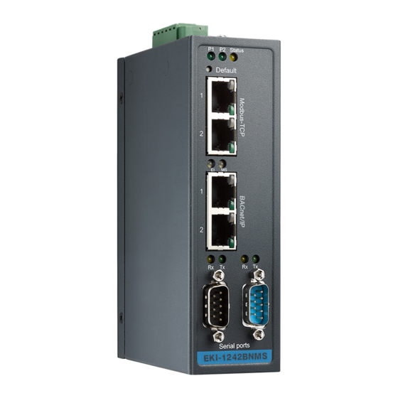
Press less than 5 seconds to restart the device, press over 5 seconds to reset to factory default. ETH port RJ45 port for Modbus/TCP and device configuration. ETH port RJ45 port for BACnet/IP. Serial port DB9 pinout. Port 1 supports BACnet MSTP and port 2 supports RS-232/422/485. EKI-1242 Series User Manual... -
Page 15: Figure 1.2 Front View (Eki-1242Ecms/Eki-1242Iecms)
Press less than 5 seconds to restart the device, press over 5 seconds to reset to factory default. ETH port RJ45 port for Modbus/TCP and device configuration. ETH port RJ45 port for EtherCAT. Serial port DB9 pinout supports 232/422/485. EKI-1242 Series User Manual... -
Page 16: Figure 1.3 Front View (Eki-1242Eims/Eki-1242Ieims)
Press less than 5 seconds to restart the device, press over 5 seconds to reset to factory default. ETH port RJ45 port for Modbus/TCP and device configuration. ETH port RJ45 port for EtherNet/IP. Serial port DB9 pinout supports 232/422/485. EKI-1242 Series User Manual... -
Page 17: Figure 1.4 Front View (Eki-1242Pnms/Eki-1242Ipnms)
Press less than 5 seconds to restart the device, press over 5 seconds to reset to factory default. ETH port RJ45 port for Modbus/TCP and device configuration. ETH port RJ45 port for PROFINET. Serial port DB9 pinout supports 232/422/485. EKI-1242 Series User Manual... -
Page 18: Rear View
Figure 1.6 Top View No. Item Description Wall mounting Screw (x4) used in the installation of a wall mounting plate screws Terminal block Connect cabling for power and alarm wiring Ground terminal Screw terminal used to ground chassis EKI-1242 Series User Manual... -
Page 19: Bottom View
Power 2 is off or power error condition exists Status Orange Blinking: System is ready Solid: – Restore config from SD card successfully to factory default state during booting – Backup config to SD card successfully during booting System is powered off EKI-1242 Series User Manual... - Page 20 Blinking (200ms ON, 700ms OFF): EtherCAT is SafeOP state Solid: EtherCAT is OP state EtherCAT is Init-state Modbus (MS) Orange Blinking: One of Modbus transaction query failed Green Solid: All Modbus transactions query successfully No Modbus transmission EKI-1242 Series User Manual...
- Page 21 EtherNET/IP (EI) Orange Reserved Green Blinking: IO connection do not establish Solid: IO connection establish Modbus (MS) Orange Blinking: One of Modbus transaction query failed Green Solid: All Modbus transactions query successfully No Modbus transmission EKI-1242 Series User Manual...
- Page 22 Off: No link Blinking: Link and activity On: Link without activity Orange/ Off: no link Green Solid Orange: Current link speed is 100M Solid Green: Current link speed is 10M EKI-1242 Series User Manual...
-
Page 23: Dimensions
95 [3.740] 42 [1.654] 30.50 [1.201] 40 [1.575] 42 [1.654] 95 [3.740] Figure 1.9 Dimensions (EKI-1242BNMS/EKI-1242IBNMS) [1.299] [1.378] [0.591] 104 [4.094] 95 [3.740] 42 [1.654] 30.50 [1.201] 40 [1.575] 42 [1.654] 95 [3.740] Figure 1.10 Dimensions (EKI-1242ECMS/EKI-1242IECMS) EKI-1242 Series User Manual... - Page 24 95 [3.740] 42 [1.654] 30.50 [1.201] 40 [1.575] 42 [1.654] 95 [3.740] Figure 1.11 Dimensions (EKI-1242EIMS/EKI-1242IEIMS) [1.299] [1.378] [0.591] 104 [4.094] 95 [3.740] 42 [1.654] 30.50 [1.201] 40 [1.575] 42 [1.654] 95 [3.740] Figure 1.12 Dimensions (EKI-1242PNMS/EKI-1242IPNMS) EKI-1242 Series User Manual...
-
Page 25: Chapter 2 Fieldbus Gateway Installation
Chapter Fieldbus Gateway Installation... -
Page 26: Installation Guidelines
In this instruction, it will explain how to find a proper location for your Fieldbus Gateways, and how to connect to the network, hock up the power cable, and connect to the EKI-1242 Series. Verifying Fieldbus Gateway Operation Before installing the device in a rack or on a wall, power on the fieldbus gateway to verify that the fieldbus gateway passes the power-on self-test (POST). -
Page 27: Installing The Fieldbus Gateway
DIN rail clip. If seated correctly, the bottom of the DIN rail should be fully inserted in the release tab. DIN rail clip DIN rail DIN rail clip release tab Figure 2.1 Installing the DIN-Rail Mounting Kit EKI-1242 Series User Manual... -
Page 28: Figure 2.2 Correctly Installed Din Rail Kit
Push down on the top of the DIN rail clip release tab with your finger. As the clip releases, lift the bottom of the fieldbus gateway, as shown in the following illustration. Figure 2.3 Removing the DIN-Rail EKI-1242 Series User Manual... -
Page 29: Wall-Mounting
Align the wall mounting plates on the rear side. The screw holes on the device and the mounting plates must be aligned, see the following illustration. Secure the wall mount plates with the provided screws, see the following figure. Figure 2.4 Installing Wall Mount Plates EKI-1242 Series User Manual... -
Page 30: Figure 2.5 Wall Mounting Screw Dimensions
Install the wall mount plate on the screws and slide it forward to lock in place, see the following figure. Figure 2.6 Wall Mount Installation Once the device is installed on the wall, tighten the screws to secure the device. EKI-1242 Series User Manual... -
Page 31: Connecting The Fieldbus Gateway To Ethernet Ports
Pin 2 Figure 2.7 Ethernet Plug & Connector Pin Position Maximum cable length: 100 meters (328 ft.) for 10/100BaseT. Serial Connection EKI-1242 Series provides eight ports DB9 (male) connectors. RS-232/422/485 pin assignments as below: Figure 2.8 DB 9 Pin Position RS-232... -
Page 32: Microsd Card Installation
MicroSD Card Installation The EKI-1242 Series provides an easy way to backup, restore, and deploy configuration settings. The fieldbus gateway provides a microSD card slot to support simple means to manage system configuration settings. Only microSD cards with the FAT32 or exFAT file systems are supported. -
Page 33: Utilizing A Microsd Card
Check that the microSD card is not write-protected. Check that the file system is not corrupted. Check that the microSD card is not damaged. If any of the events occur, the fieldbus gateway halts operation and the status LED begins flashing. EKI-1242 Series User Manual... -
Page 34: Power Supply Installation
EKI-1242 Series support 12 to 48 V . Dual power inputs are supported and allow you to connect a backup power source. -
Page 35: Considerations
Caution! Do not service equipment or cables during periods of lightning activity. Caution! Do not service any components unless qualified and authorized to do Caution! Do not block air ventilation holes. EKI-1242 Series User Manual... -
Page 36: Wiring A Relay Contact
2.7.4 Wiring a Relay Contact The following section details the wiring of the relay output. The terminal block on the EKI-1242 Series is wired and then installed onto the terminal receptor located on the EKI-1242 Series. PWR2 1A@24V... -
Page 37: Wiring The Power Inputs
Make sure the power is not connected to the fieldbus gateway or the power converter before proceeding. Loosen the screws securing terminal block to the terminal block receptor. Remove the terminal block from the fieldbus gateway. Figure 2.20 Removing a Terminal Block EKI-1242 Series User Manual... -
Page 38: Reset Button
Reset configuration to factory default: Press and hold the Reset button for 5 seconds. System reboot: Press and hold the Reset button for 2 seconds. Note! Do NOT power off the fieldbus gateway when loading default settings. EKI-1242 Series User Manual... -
Page 39: Chapter 3 Managing Fieldbus Gateway
Chapter Managing Fieldbus Gateway... -
Page 40: Log In
In the Password field, type in the new password. Re-type the same password in the Confirmation field. Click Apply to change the current settings. Figure 3.2 Changing a Default Password After saving all the desired settings, perform a system save (System Management > Apply Configuration). The changes are saved. EKI-1242 Series User Manual... -
Page 41: Overview
Displays the IP address setting mode of the device. IP Address Displays the assigned IP address of the device. Subnet Mask Displays the assigned subnet mask of the device. Gateway Displays the assigned gateway of the device. EKI-1242 Series User Manual... -
Page 42: Figure 3.5 Overview > Device Information > Bacnet/Ip
Displays the IP address setting mode of the device. IP Address Displays the assigned IP address of the device. Subnet Mask Displays the assigned subnet mask of the device. Gateway Displays the assigned gateway of the device. EKI-1242 Series User Manual... -
Page 43: Diagnose
Packets. The ensuing table for I/O Connection table settings is for reference only: UP Time, Originator, Receive Address, O->T Packets, T->O Packets, O->T Connection ID, O->T RPI (ms), T->O Connection ID and T->O RPI (ms). EKI-1242 Series User Manual... -
Page 44: Data View
1242EIMS/EKI-1242IEIMS, monitor EtherCAT input data for EKI-1242ECMS/EKI- 1242IECMS and Profinet slot data for EKI-1242PNMS/EKI-1242IPNMS. To access this page, click Overview > Data View. The following figure displays the menu as found in the EKI-1242BNMS/EKI- 1242IBNMS. Figure 3.8 Overview > Data View EKI-1242 Series User Manual... -
Page 45: Figure 3.9 Overview > Data View
The following figure displays the menu as found in the EKI-1242ECMS/EKI- 1242IECMS. Figure 3.9 Overview > Data View The following table describes the items in the previous figure. Item Description Auto Refresh Check the option to automatically have the table refresh the information. EKI-1242 Series User Manual... -
Page 46: Figure 3.10 Overview > Data View
The following figure displays the menu as found in the EKI-1242EIMS/EKI- 1242IEIMS. Figure 3.10 Overview > Data View The following table describes the items in the previous figure. Item Description Auto Refresh Check the option to automatically have the table refresh the information. EKI-1242 Series User Manual... -
Page 47: Figure 3.11 Overview > Data View
The following figure displays the menu as found in the EKI-1242PNMS/EKI- 1242IPNMS. Figure 3.11 Overview > Data View EKI-1242 Series User Manual... -
Page 48: Network Setting
Unchecked the option to use two different IP subnet on Modbus/TCP and BACnet/IP interface. In this mode, the BACnet ports of Modbus/ TCP and BACnet/IP are not bridged, so the traffic can't be forwarded between these interfaces. EKI-1242 Series User Manual... -
Page 49: Figure 3.13 Network Setting > Ip Setting
Enter a value to specify the IP address of the interface. The default is 192.168.1.1. Subnet Mask Enter a value to specify the IP subnet mask for the interface. The default is 255.255.255.0. Gateway Enter a value to specify the default gateway for the interface. The default is 192.168.1.254. EKI-1242 Series User Manual... -
Page 50: Figure 3.14 Network Setting > Ip Setting
TCP and EtherNet/IP are not bridged, so the traffic can't be forwarded between these interfaces. EtherNet/IP IP Address Setting Mode Click the drop-down menu to select the IP Address Setting mode: Static address, or DHCP client. EKI-1242 Series User Manual... -
Page 51: Figure 3.15 Network Setting > Ip Setting
Enter a value to specify the IP address of the interface. The default is 0.0.0.0. Subnet Mask Enter a value to specify the IP subnet mask for the interface. The default is 0.0.0.0. Gateway Enter a value to specify the default gateway for the interface. The default is 0.0.0.0. EKI-1242 Series User Manual... -
Page 52: Serial Settings
Click the drop-down menu to select the stop bits: 1, 1.5 or 2. Flow Control Click the drop-down menu to select the flow control mode: None, XOn/XOff or RTS/CTS. Submit Click Submit to save the values and update the screen. EKI-1242 Series User Manual... -
Page 53: Protocol Setting
Enter the value to specify the device identifier. Mode Click the drop-down menu to select the BACnet mode: IP or MSTP. Max. Masters Available under MSTP mode. Enter the variable defining the maximum number of masters. EKI-1242 Series User Manual... -
Page 54: Ethercat Setting
64 bytes of data coming from the Modbus/ TCP network can feature the Modbus exception codes. The EtherNet/IP Setting page is only available for EKI-1242EIMS/EKI-1242IEIMS. To access this page, click Protocol Setting > EtherNet/IP Setting. Figure 3.20 Protocol Setting > EtherNet/IP Setting EKI-1242 Series User Manual... -
Page 55: Profinet Setting
Enter the value for the SNMP Read Only Community string Read Only Community (default: public). Read / Write Enter the value for the SNMP Read/Write Community string Community (default: private). Submit Click Submit to save the values and update the screen. EKI-1242 Series User Manual... -
Page 56: Modbus Setting
Quantity, Trigger, Scan Interval, Data Swap, Response Timeout, I/O Disconnect, Safe Value, Add (click to add a new transaction), Edit (click to modify existing transactions), Delete (click to delete existing transactions), Copy (click to copy an existing transaction) and FlowCtrl Status. EKI-1242 Series User Manual... -
Page 57: Figure 3.23 Protocol Setting > Modbus Setting > Add
BNMS models: port 1 is dedicated for BACnet, port 2 is dedicated for Modbus. Non BNMS models: select the serial interface where the remote Modbus/RTU device is located. Slave ID Enter the Modbus/TCP server slave ID. EKI-1242 Series User Manual... - Page 58 Write safe value: The value to transmit for each element. Stop: The transmission of any and all data to the Modbus server is halted. Submit Click Submit to save the values and update the screen. Back Click Back to return the previous page. EKI-1242 Series User Manual...
-
Page 59: Mapping Overview
Transaction Name, In Slot Range(bytes), Input Word and Output Word. The ensuing table for Modbus Client table settings is for reference only: Name, FC, Data Swap, Scan Time, Response Timeout, UID, Read/Write Starting Address, Quantity and When PROFINET doesn't exchange I/O. EKI-1242 Series User Manual... -
Page 60: System Management
Click the radio button to select the backup file destination. Restore Backup Click Browse to select the configuration file. Upload Archive Click Upload Archive to restore configuration to the device. From Click the radio-button to select upload file source. EKI-1242 Series User Manual... -
Page 61: Upgrade Manager
All changes that have been made will be lost, even if you have issued a save. Reset settings take effect after a system reboot. Figure 3.28 System Management > Reset System 3.6.5 Reboot Device To access this page, click System Management > Reboot Device. EKI-1242 Series User Manual... -
Page 62: Apply Configuration
Click Apply and Reboot to have configuration changes you have made to be saved across a system reboot. All changes submitted since the previous save or system reboot will be retained by the device. Figure 3.30 System Management > Apply Configuration EKI-1242 Series User Manual... -
Page 63: Tools
Stop Click Stop to stop capturing the data. Export Click Export to export and download the captured data. Auto Scroll Check the option to cycle through all of the data screens automatically while start capturing data. EKI-1242 Series User Manual... - Page 64 No part of this publication may be reproduced in any form or by any means, electronic, photocopying, recording or otherwise, without prior written permission of the publisher. All brand and product names are trademarks or registered trademarks of their respective companies. © Advantech Co., Ltd. 2018...
Need help?
Do you have a question about the EKI-1242 Series and is the answer not in the manual?
Questions and answers