Advantech EKI-1221 User Manual
1/2/4-port modbus data gateway
Hide thumbs
Also See for EKI-1221:
- User manual (80 pages) ,
- User manual (64 pages) ,
- User manual (62 pages)
Table of Contents
Advertisement
Advertisement
Table of Contents

Subscribe to Our Youtube Channel
Related Manuals for Advantech EKI-1221


Summary of Contents for Advantech EKI-1221
- Page 1 User Manual EKI-1221, EKI-1222, EKI-1224 1/2/4-port Modbus Data Gateway...
- Page 2 No part of this manual may be reproduced, copied, translated or transmitted in any form or by any means without the prior written permission of Advantech Co., Ltd. Information provided in this manual is intended to be accurate and reliable. How- ever, Advantech Co., Ltd.
-
Page 3: Declaration Of Conformity
This product has passed the CE test for environmental specifications when shielded cables are used for external wiring. We recommend the use of shielded cables. This kind of cable is available from Advantech. Please contact your local supplier for ordering information. -
Page 4: Safety Instructions
The sound pressure level at the operator's position according to IEC 704-1:1982 is no more than 70 dB (A). DISCLAIMER: This set of instructions is given according to IEC 704-1. Advantech disclaims all responsibility for the accuracy of any statements contained herein. -
Page 5: Table Of Contents
Table 2.2: EKI-1221/1222/1224 LED Indicators ......9 2.2.2 Dimensions (Units: mm).............. 10 Figure 2.3 Front View of EKI-1221 ..........10 Figure 2.4 Side View of EKI-1221..........10 Figure 2.5 Back View of EKI-1221..........11 Figure 2.6 Top View of EKI-1221..........11 Figure 2.7 Front View of EKI-1222 .......... - Page 6 Administrator Setting................35 3.8.1 Import/Export Serial Port Setting ..........36 3.8.2 Locate the Modbus Data Gateway ..........36 3.8.3 Lock Device ................37 3.8.4 Restore to Factory Default Settings..........38 3.8.5 Update Firmware ................ 39 EKI-1221/1222/1224 User Manual...
-
Page 7: Chapter 1 Introduction
Chapter Introduction... -
Page 8: Overview
“slave” devices and write real-time data over RS-232, RS-422, or RS- 485 serial data communication. The EKI-1221/1222/1224 provides a feature that can allow users to select master or slave operation for each serial port. EKI-1221/1222/ 1224 not only allows Ethernet master can control serial slaves, but it can also allow serial masters to control Ethernet slaves. -
Page 9: Specifications
RS-485: Data+, Data-, GND Protection: 15 KV ESD for all signals, enhanced protection for RS-422/485 lines Software Utility: Advantech Serial Device Server Configuration Utility OS Support: Windows 2000/XP/Vista (x86) Operation Mode: RTU Master, RTU Slave, ASCII Master, ASCII Slave General LED indicators: –... -
Page 10: Package Check List
Operating Humidity: 5 to 95 % RH Regulatory Approvals ECM: CE Class A, FCC Part 15 Subpart B Class A Safety: UL (UL60950-1) Package Check List One EKI Modbus Data Gateway Panel mounting bracket CD-ROM for configuration utility and user manual EKI-1221/1222/1224 User Manual... -
Page 11: Chapter 2 Getting Started
Chapter Getting Started... -
Page 12: Understanding Eki-1221/1222/1224
The communication mode of Modbus can be ASCII, RTU, or TCP/IP. The EKI-1221/1222/1224 is used to support applications such as protocol conversion between serial (Modbus/ASCII or Modbus/RTU) and networked (Modbus/ TCP) Modbus devices or it can be used to bridge Modbus serial devices over TCP/IP network. -
Page 13: Figure 2.1 Modbus System Architecture 1
The basic system architecture is as below: Figure 2.1 Modbus System Architecture 1 Figure 2.2 Modbus System Architecture 2 EKI-1221/1222/1224 User Manual... -
Page 14: Modbus Rtu
TCP frame that has a six-byte header in Modbus/TCP protocol. Modbus/TCP enables the use of Modbus messaging in an Intranet running the TCP/ IP protocols. Modbus/TCP is most commonly used for Ethernet attachment of PLC’s or I/O modules to other simple field buses or I/O networks. EKI-1221/1222/1224 User Manual... -
Page 15: Hardware
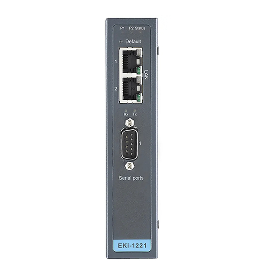
LED Indicators There are LEDs display the two sets of power status, system status, dual networks status, and serial communication status on the front panel of EKI-1221, EKI-1222, and EKI-1224. Each of them has its own specific meaning as below table. -
Page 16: Dimensions (Units: Mm)
2.2.2 Dimensions (Units: mm) EKI-1221: Figure 2.3 Front View of EKI-1221 Figure 2.4 Side View of EKI-1221 EKI-1221/1222/1224 User Manual... -
Page 17: Figure 2.5 Back View Of Eki-1221
Figure 2.5 Back View of EKI-1221 Figure 2.6 Top View of EKI-1221 EKI-1221/1222/1224 User Manual... -
Page 18: Figure 2.7 Front View Of Eki-1222
EKI-1222: Figure 2.7 Front View of EKI-1222 Figure 2.8 Side View of EKI-1222 EKI-1221/1222/1224 User Manual... -
Page 19: Figure 2.9 Back View Of Eki-1222
Figure 2.9 Back View of EKI-1222 Figure 2.10 Top View of EKI-1222 EKI-1221/1222/1224 User Manual... -
Page 20: Figure 2.11Front View Of Eki-1224
EKI-1224: Figure 2.11 Front View of EKI-1224 Figure 2.12 Side View of EKI-1224 EKI-1221/1222/1224 User Manual... -
Page 21: Figure 2.13Back View Of Eki-1224
Figure 2.13 Back View of EKI-1224 Figure 2.14 Top View of EKI-1224 EKI-1221/1222/1224 User Manual... -
Page 22: Connecting Hardware
Connecting Hardware In this instruction, it will explain how to find a proper location for your EKI-1221/1222/ 1224, and how to connect to the network, hock up the power cable, and connect to the EKI-1221/1222/1224. 2.3.1 Choosing the Location Due to its versatility and innovative design, the EKI-122/1222/1224 can be:... -
Page 23: Figure 2.16Din-Rail Step 1
DIN-rail Mounting The EKI-1221/1222/1224 can be mounted on a standard DIN-rail. The DIN-rail kit is screwed on the Modbus data gateway when out of factory. If the DIN-rail kit is not screwed on the EKI-1221/1222/1224, please screw the DIN-rail kit on the Modbus data gateway first. -
Page 24: Connecting Power
2.3.2 Connecting Power The EKI-1221/1222/1224 supports dual +12 to 48 VDC power inputs and a power-fail relay output. Following figure is the power terminal block pin assignments. Please refer it to connect to the proper power requirements and polarity. Figure 2.18 Power Connector You can connect an alarm indicator, buzzer or other signaling equipment through the power-fail relay output. -
Page 25: Chapter 3 Configuration
Chapter Configuration... -
Page 26: Installing The Configuration Utility
Installing the Configuration Utility The following section will show you how to install Advantech Serial Device Server Configuration Utility, a tool to set up and monitor the EKI series Modbus Data Gateways. Note Be sure the Microsoft .NET Framework on your host PC is greater than version 2.0 . - Page 27 5. Carefully read the Software License Agreement, and press “Yes” to continue. 6. The InstallShield will specify a default installation path, C:\Program Files\Advantech eAutomation\Serial Device Server Configuration Utility. You may change the destination directory by clicking on “Browse…” click “Next” to finish the installation.
- Page 28 7. Click “Next” to start copying the software files. 8. After few minutes, a message will indicate that Configuration Utility is suc- cessfully installed, click “Finish” to exit the InstallShield. EKI-1221/1222/1224 User Manual...
-
Page 29: Starting The Configuration Utility
PC to enhance network security. With this secure function enabled, other PCs will not have permission for configuration. After the installation program on the Advantech IEDG Series Driver Utility CD-ROM is finished, the serial device servers will be ready for use and configure. -
Page 30: Discovering Modbus Data Gateways
3.3.1 Auto Searching Advantech Serial Device Server Configuration Utility will automatically search all the EKI, ADAM and EDG series device servers on the network and show them on the Serial Device Server List Area of the utility. The Utility provides an auto-searching function to show your device(s) by simply executing the configuration utility program from the Start Menu. - Page 31 Click on the “+” before the device name, and the utility will expand the communication interfaces on this Modbus data gateway. Click on each interface item, you will entry the configuration page to modify the set- ting. The configuration will be introduced on following sections. EKI-1221/1222/1224 User Manual...
- Page 32 EKI-1221/1222/1224 User Manual...
-
Page 33: Clear Device List And Search Again
Using “Add IP address to Favorite” or “Search a Range of IP addresses” functions, you are allowed to add one device or group of devices to “Favorites”. These devices can locate on local network domain or other network domain. EKI-1221/1222/1224 User Manual... -
Page 34: Setting Ethernet Parameters
And clink on the “+” before the device name, and utility will expand the communication interfaces on this Modbus data gateway. Select the Ethernet interface (Eth1 or Eth2, these are two individual Ethernet ports). EKI-1221/1222/1224 User Manual... -
Page 35: Setting Serial Communication Parameters
IP Address, Subnet Mask, Default Gateway: The IP address identifies your Modbus data gateway on the global network. Each EKI-1221/1222/1224 has the same default IP address 10.0.0.1 and 10.0.0.2 for dual Ethernet ports. Obtain these specific IP addresses from your network administrator and then configure each Advantech Modbus data gateway with individual IP addresses, related Subnet Mask and Gateway Setting. -
Page 36: Basic Configuration
RS-422. You can use any one of these serial interfaces according to your require- ments. You must also pay special attention to the wiring scheme of the EKI-1221/ 1222/1224 serial connection to make sure it conforms to the serial type you select. - Page 37 Modbus device (i.e. Modbus/ASCII or Modbus/RTU). Parity None Even or Odd Data bits Stop bits Modbus/ASCII Parity None Even or Odd Data bits Stop bits Modbus/RTU Flow Control: The EKI-1221/1222/1224 provides four options: None, XOn/XOff, RTS/CTS, and DTR/DSR. EKI-1221/1222/1224 User Manual...
-
Page 38: Operation Configuration
Modbus/RTU or Mod- bus ASCII. After the timeout is expired and no response is received, the EKI-1221/ 1222/1224 will regard the command as failed. Note that the timeout for the host PC must be greater than the timeout setting here specified, otherwise an error will occur. - Page 39 This option specifies the time duration in milliseconds for the EKI-1221/1222/1224 to wait for a response after it has issued a command while using Modbus/RTU or Mod- bus ASCII. After the timeout is expired and no response is received, the EKI-1221/ 1222/1224 will regard the command as failed.
-
Page 40: Function Accessible Setting
Function Accessible Setting The EKI-1221/1222/1224 provides a security function that the utility allows to set up an accessible IP list for Modbus TCP devices which can access data from Modbus data gateway. Allow any IP access: The default option, any Modbus TCP device can communicate with this Modbus data gateway. -
Page 41: Monitoring Modbus Status
(the default value is 1000ms). Administrator Setting The configuration utility provides several administrator settings for easy management and configuration. Right click the mouse on the device name in the sub-tree of Serial Device Sever List Area, and select these administrator settings. EKI-1221/1222/1224 User Manual... -
Page 42: Import/Export Serial Port Setting
If there are many Modbus data gateways need your management, you may need to identify which unit is correct to configuration on utility. Click “Locate” to make that unit’s “Status” LED be steady on until you click “Stop Locate”. EKI-1221/1222/1224 User Manual... -
Page 43: Lock Device
If you forgot the password, the only way to solve this problem is to restore the setting of the Modbus data gateway to the factory default which will be introduced next section. EKI-1221/1222/1224 User Manual... -
Page 44: Restore To Factory Default Settings
Then, please power off the Modbus data gateway within ten seconds, after recon- necting the power back, the all setting will be reset to the factory default. If the power remains more than ten seconds, the Modbus data gateway will not have any changes. EKI-1221/1222/1224 User Manual... -
Page 45: Update Firmware
3.8.5 Update Firmware Advantech continually upgrades its firmware to keep up with the ever-expending world of computing. You can use the update firmware function in the utility to carry upgrade procedure. Please access Advantech’s website: to download the latest version of the firmware. - Page 46 Select the firmware file you want to update. After downloading the firmware completely, click “OK” button, and the Modbus data gateway will restart automatically. EKI-1221/1222/1224 User Manual...
- Page 47 EKI-1221/1222/1224 User Manual...
- Page 48 No part of this publication may be reproduced in any form or by any means, electronic, photocopying, recording or otherwise, without prior written permis- sion of the publisher. All brand and product names are trademarks or registered trademarks of their respective companies. © Advantech Co., Ltd. 2008...
Need help?
Do you have a question about the EKI-1221 and is the answer not in the manual?
Questions and answers