Table of Contents
Advertisement
Quick Links
Advertisement
Table of Contents

Related Manuals for Advantech EKI-1228-DR Series


Summary of Contents for Advantech EKI-1228-DR Series
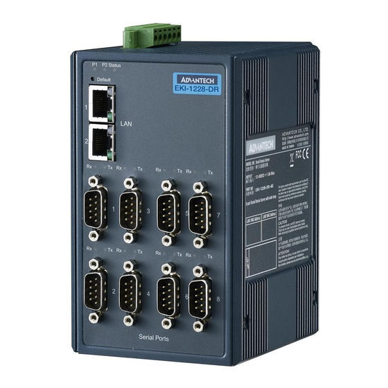
- Page 1 User Manual EKI-1228-DR Series 8-port Modbus Gateway...
- Page 2 No part of this manual may be reproduced, copied, translated or transmitted in any form or by any means without the prior written permission of Advantech Co., Ltd. Information provided in this manual is intended to be accurate and reliable.
-
Page 3: Declaration Of Conformity
Technical Support and Assistance Visit the Advantech web site at www.advantech.com/support where you can find the latest information about the product. Contact your distributor, sales representative, or Advantech's customer service center for technical support if you need additional assistance. -
Page 4: Packing List
Before setting up the system, check that the items listed below are included and in good condition. If any item does not accord with the table, please contact your dealer immediately. 1 x 8-port Modbus gateway 1 x DIN-Rail Mounting Bracket and Screws 1 x Wall-mounting Bracket EKI-1228-DR Series User Manual... -
Page 5: Safety Instructions
The sound pressure level at the operator's position according to IEC 704-1:1982 is no more than 70 dB (A). DISCLAIMER: This set of instructions is given according to IEC 704-1. Advantech disclaims all responsibility for the accuracy of any statements contained herein. EKI-1228-DR Series User Manual... - Page 6 Always disconnect the power from the device before servicing it. Before plugging a cable into any port, discharge the voltage stored on the cable by touching the electrical contacts to the ground surface. EKI-1228-DR Series User Manual...
-
Page 7: Table Of Contents
Accessing the Web Page via Configuration Utility...... 36 4.2.2 Accessing the Web Page via Web Browser ....... 37 System ....................37 Ethernet Configuration ................38 Port Configuration ................... 40 4.5.1 Basic ................... 40 4.5.2 Operation ..................41 EKI-1228-DR Series User Manual... - Page 8 Reboot ..................50 Management ................... 50 4.9.1 Change Password............... 50 4.9.2 Export Device Settings..............51 4.9.3 Import Device Settings..............51 Chapter TCP and UDP Port Numbers.....52 List of Known TCP and UDP Port Numbers..........53 viii EKI-1228-DR Series User Manual...
- Page 9 Figure 2.11 Ethernet Plug & Connector Pin Position..............13 Figure 2.12 DB9 Pin Assignment ....................13 Figure 2.13 Power Wiring for EKI-1228-DR Series ................ 14 Figure 2.14 Grounding Connection ....................16 Figure 2.15 Terminal Receptor: Relay Contact ................16 Figure 2.16 Terminal Receptor: Power Input Contacts ..............
- Page 10 Figure 4.17 Tools > Ping ........................ 49 Figure 4.18 Tools > Reboot ......................50 Figure 4.19 Management > Change Password ................50 Figure 4.20 Management > Import ....................51 EKI-1228-DR Series User Manual...
-
Page 11: Introduction
Chapter Introduction... -
Page 12: Overview
Overview The EKI-1228-DR Series Modbus gateways are bi-directional gateways for integrating new and existing Modbus/RTU and Modbus/ASCII serial devices to newer TCP/IP networked-based devices. The EKI-1228-DR Series has two independent Ethernet ports and MAC addresses to provide redundancy and reliability. They provide a simple and cost-effective way to bring remote management and data accessibility to thousands of devices that cannot connect to a network. -
Page 13: Specifications
12 ~ 48V , redundant dual inputs Software Driver Support 32-bit/64-bit Windows XP/Vista/7/8/8.1/10, Windows Server 2003/2008/2008 R2/2012/2012 R2 Utility Advantech EKI Device Configuration Utility Operation Modes Modbus RTU Master/Slave mode Modbus ASCII Master/Slave mode Configuration Windows Utility, Web Browser... -
Page 14: Dimensions
Dimensions 83.50 [3.29] 50.67 [1.99] 95 [3.74] 104.00 [4.09] 86.60 [3.41] 95.00 [3.74] 9.00 [0.35] 95.00 [3.74] 86.60 [3.41] 66.00 [2.60] EKI-1228 Figure 1.1 Dimensions EKI-1228-DR Series User Manual... -
Page 15: Getting Started
Chapter Getting Started... -
Page 16: Hardware
Press at least 10secs to reset device to default settings. ETH port RJ45 ports x 2. See “LED Indicators” on page 8 for further details. Serial port DB9 pinout, supports RS-232/422/485. See “LED Indicators” on page 8 for further details. EKI-1228-DR Series User Manual... -
Page 17: Rear View
Mounting plate used for the installation to a standard DIN rail plate 2.1.3 Top View Figure 2.3 Top View No. Item Description Terminal block Connect cabling for power and alarm wiring Ground terminal Screw terminal used to ground chassis EKI-1228-DR Series User Manual... -
Page 18: Led Indicators
Blinking: Ethernet port is transmitting or receiving activity data indicator On: 10Mbps or 100Mbps link Serial Amber (Rx) Serial port is receiving data Green (Tx) Serial port is transmitting data No data is being transmitted or received through the serial port EKI-1228-DR Series User Manual... -
Page 19: Connecting Hardware
DIN rail clip. If seated correctly, the bottom of the DIN rail should be fully inserted in the release tab. DIN rail clip DIN rail DIN rail clip release tab Figure 2.5 Installing the DIN-Rail Mounting Kit EKI-1228-DR Series User Manual... -
Page 20: Figure 2.6 Correctly Installed Din Rail Kit
Push down on the top of the DIN rail clip release tab with your finger. As the clip releases, lift the bottom of the switch, as shown in the following illustration. Figure 2.7 Removing the DIN-Rail EKI-1228-DR Series User Manual... -
Page 21: Wall-Mounting
Use the wall mount plates as a guide to mark the locations of the screw holes. Drill four holes over the four marked locations on the wall, keeping in mind that the holes must accommodate wall sinks in addition to the screws. Insert the wall sinks into the walls. EKI-1228-DR Series User Manual... -
Page 22: Figure 2.9 Securing Wall Mounting Screws
Install the wall mount plate on the screws and slide it forward to lock in place, see the following figure. Figure 2.10 Wall Mount Installation Once the device is installed on the wall, tighten the screws to secure the device. EKI-1228-DR Series User Manual... -
Page 23: Connecting The Switch To Ethernet Ports
Figure 2.11 Ethernet Plug & Connector Pin Position Maximum cable length: 100 meters (328 ft.) for 10/100BaseT. 2.2.4 Serial Connection EKI-1228-DR Series provides up to four ports DB9 (male) connectors. RS-232/422/ 485 pin assignments as below: Figure 2.12 DB9 Pin Assignment RS-232... -
Page 24: Power Connection
EKI-1228-DR Series support 12 to 48 V . Dual power inputs are supported and allow you to connect a backup power source. -
Page 25: Considerations
Caution! Do not service equipment or cables during periods of lightning activity. Caution! Do not service any components unless qualified and authorized to do EKI-1228-DR Series User Manual... -
Page 26: Wiring A Relay Contact
2.2.9 Wiring a Relay Contact The following section details the wiring of the relay output. The terminal block on the EKI-1228-DR Series is wired and then installed onto the terminal receptor located on the EKI-1228-DR Series. DC12-48V PWR2... -
Page 27: Wiring The Power Inputs
Insert a small flat-bladed screwdriver in the V1+/V1- wire-clamp screws, and loosen the screws. Insert the negative/positive DC wires into the V+/V- terminals of PW1. If setting up power redundancy, connect PW2 in the same manner. EKI-1228-DR Series User Manual... -
Page 28: Reset Button
Reset Button Reset configuration to factory default: Press and hold Reset button for 10 seconds. System reboot: Press and hold Reset button for 2 seconds. Note! Do NOT power off the Ethernet switch when loading default settings. EKI-1228-DR Series User Manual... -
Page 29: Utility Configuration
Chapter Utility Configuration... -
Page 30: Installing The Configuration Utility
Microsoft.NET Framework version 2.0 or greater is required for this application. Insert the Advantech EKI Device Configuration Utility CD-ROM into the CD- ROM drive (whereas E:\ is the drive name of your CD-ROM) on the host PC. Use Windows explorer or the Windows Run command to execute the setup program, the path for the setup program on the CD-ROM is as follows: E:\EKI_Device_Configuration_Utility_v2.01.exe... -
Page 31: Figure 3.2 Installshield Wizard 2 Of 4
Figure 3.2 InstallShield Wizard 2 of 4 The InstallShield continues and a status screen displays. The default installation path is C:\Program Files\EKI Device Configuration Utility. Figure 3.3 InstallShield Wizard 3 of 4 EKI-1228-DR Series User Manual... -
Page 32: Figure 3.4 Installshield Wizard 4 Of 4
Once the installation of the package is finished a Configuration Utility Setup screen displays. Click Finish to conclude the process and exit the InstallShield Wizard. Figure 3.4 InstallShield Wizard 4 of 4 EKI-1228-DR Series User Manual... -
Page 33: Starting The Configuration Utility
Utility CD-ROM is finished, the serial device servers are ready for use and configuration. Advantech Serial Device Server Configuration Utility is an excellent device server management tool. You can connect and configure the local and remote Advantech serial device servers easily. The utility provides access to the following functions: ... -
Page 34: Discovering Your Device Server
Auto Searching Advantech Serial Device Server Configuration Utility will automatically search all the EKI-1228-DR Series device servers on the network and show them on the Serial Device Server List Area of the utility. The utility provides an auto-search function to show your device (s) by simply executing the configuration utility program from the Start Menu. -
Page 35: Figure 3.7 Selecting A Group
Click on the “+” before the device name, and the utility will expand the interfaces on this device server. Figure 3.8 Selecting a Device Click on each item to enter the configuration page to change the setting. The configuration will be introduced on following sections. Figure 3.9 Viewing Basic Settings EKI-1228-DR Series User Manual... -
Page 36: Network Settings
10.0.0.1 (Eth1) 10.0.0.2 (Eth2) The EKI-1228-DR Series includes a software utility option, which you can install on your system, for configuration through computer-based software. The EKI-1228-DR Series also includes a web interface option for configuration through a standard web browser. -
Page 37: Figure 3.11 Network Settings Overview
DNS server. Secondary DNS Server is included for use when Primary DNS server is unavailable. Note! When you have finished the configuration of these settings for each category, please press the “Apply” button in order to make these settings effective on the Serial Device Server. EKI-1228-DR Series User Manual... -
Page 38: Administrator Settings
From the device list frame, locate the desired device and right-click on it to display the settings menu. Select Locate from the menu. Figure 3.12 Locate the Serial Device Server The unit’s Status LED will turn solid amber and the buzzer will sound until you click Stop Locate. EKI-1228-DR Series User Manual... -
Page 39: Securing The Serial Device Server
Right-click a desired device to display the settings menu. Select Lock Device. Figure 3.13 Lock the Serial Device Server Enter a password. Retype the password entry to confirm the profile password. Figure 3.14 Enter a Password EKI-1228-DR Series User Manual... -
Page 40: Figure 3.15 Reset Device
Enter the password as entered in the Lock Device procedure. Figure 3.16 Unlock the Serial Device Server If you forgot the password, you must restore the setting of the serial device server to the factory defaults, which will be introduced in the next section. EKI-1228-DR Series User Manual... -
Page 41: Restore To Factory Default Settings
Power off the serial device server within ten seconds. After reconnecting the power, all settings will be reset to the factory default. If the power supply remains connected for more than ten seconds, the serial device server will not be changed. EKI-1228-DR Series User Manual... -
Page 42: Resetting The Device
Right-click a desired device to display the settings menu. Select Reset Device. Figure 3.18 Reset Device The device resets. Once the process is complete, the serial device server displays under the Serial Device Server listing once again. EKI-1228-DR Series User Manual... -
Page 43: Add To Favorite
The Add to Favorite function allows to easily map available devices to Favorite’s. By bookmarking specific devices, you can create quickly accessible shortcuts for existing critical devices from the vast pool of locally or remotely networked EKI-1228- DR Series devices. Figure 3.19 Add to Favorite EKI-1228-DR Series User Manual... -
Page 44: Update Firmware
Note! Be sure that the host PC Ethernet network domain is as same as the EKI-1228-DR Series serial device server or the host PC can establish the TCP connection with the serial device server while doing the updating firmware process. -
Page 45: Web Interface
Chapter Web Interface... -
Page 46: Overview
In the browser’s address field, enter the IP Address of your EKI-1228-DR Series serial device server. The default IP setting is 10.0.0.1, but you should use the IP which you have previously assigned for this device. Once the IP is entered, you will be presented with the following windows. -
Page 47: Accessing The Web Page Via Web Browser
Displays the revision number of the device. Device Name Enter the device name: up to 31 alphanumeric characters. Device Description Enter the device description. Local Time Click Modify to set local date and time of the system. EKI-1228-DR Series User Manual... -
Page 48: Ethernet Configuration
Choose either Eth 1 or Eth 2 in the Ethernet Configuration page.Enter the corresponding values for your network environment. Once the settings are modified, press Save to keep the configurations. To access this page, click Ethernet Configuration. Figure 4.3 Ethernet Configuration EKI-1228-DR Series User Manual... - Page 49 Displays the current IP address 2 of the device. Save Click Save to save the values and update the screen. Note! All new configurations will take effect after rebooting. To reboot the device, click Tools > Reboot. EKI-1228-DR Series User Manual...
-
Page 50: Port Configuration
Click the drop-down menu to select the stop bits: 1, 1.5 or 2. Flow Control Click the drop-down menu to select the flow control mode: None, XOn/XOff, RTS/CTS or DTR/DSR Save Click Save to save the values and update the screen. EKI-1228-DR Series User Manual... -
Page 51: Operation
Modbus Master Mode or Modbus Slave Mode. To translate RTU/ASCII to TCP, use Master Mode. EKI-122X P1 P2 Defa ult Figure 4.5 Master Mode To translate TCP to RTU/ASCII, use Slave Mode. P1 P2 Defa ult EKI-122X Figure 4.6 Slave Mode EKI-1228-DR Series User Manual... -
Page 52: Figure 4.7 Port Configuration > Operation > Modbus Master Mode
Series to wait for a response after it has issued a command while using Modbus/RTU or Modbus ASCII. After the timeout is expired and no response is received, the EKI-1228-DR Series will regard the command as failed. Note that the timeout for the host PC must be greater than the timeout setting here specified, otherwise an error will occur. -
Page 53: Figure 4.8 Port Configuration > Operation > Modbus Slave Mode
Series to wait for a response after it has issued a command while using Modbus/RTU or Modbus ASCII. After the timeout is expired and no response is received, the EKI-1228-DR Series will regard the command as failed. Note that the timeout for the host PC must be greater than the timeout setting here specified, otherwise an error will occur. -
Page 54: Monitor
Click Save to save the values and update the screen. Monitor The EKI-1228-DR Series device server allows monitoring of the serial ports’ status. The serial port’s operation mode and status is available for display. The IP address of the host PC which is communicating with serial port is also displayed. -
Page 55: Statistic
Display the current CTS status of the selected port. Display the current DTR status of the selected port. Display the current DSR status of the selected port. Display the current DCD status of the selected port. EKI-1228-DR Series User Manual... -
Page 56: Connected Ip
Figure 4.11 Monitor > Connected IP The following table describes the items in the previous figure. Item Description Connected IP Displays the IP designation for the device. IP Address Displays the current connected IP address of the selected port. EKI-1228-DR Series User Manual... -
Page 57: Syslogd
Syslogd The EKI-1228-DR Series device server provides the functionality to allow network devices to send event messages to a logging server, also known as a Syslog server, by way of the Syslogd function. The Syslog protocol is supported by a wide range of devices and can be used to log different types of events. -
Page 58: Modbus Ip Mapping
This page shows the longest response time of each individual unit ID. This should be helpful for optimizing the performance. To access this page, click Syslogd > Modbus Slave Response Time. Click Clear All to clear all response information. Figure 4.16 Syslogd > Modbus Slave Response Time EKI-1228-DR Series User Manual... -
Page 59: Tools
Tools The EKI-1228-DR Series device server provides tools for access to ping and reset functions. 4.8.1 Ping The Ping page can help users diagnose ethernet problems. Users can use the ping page to ask the device to ping a specific target to check the Ethernet network status. -
Page 60: Reboot
Management The EKI-1228-DR Series device server allows for easy installation and maintenance and reliable maintenance access from anywhere. With the reliable management tools available, you can streamline staffing and troubleshooting requirements to a centralized system. -
Page 61: Export Device Settings
To access this page, click Management > Import. Figure 4.20 Management > Import The following table describes the items in the previous figure. Item Description Choose File Click Choose File to select the configuration file. Submit Click Submit to backup the settings. EKI-1228-DR Series User Manual... -
Page 62: Chapter 5 Tcp And Udp Port Numbers
Chapter TCP and UDP Port Numbers... -
Page 63: List Of Known Tcp And Udp Port Numbers
(TDP) (TDP) Telnet (TDP) SMTP (Mail Client) (TCP/UDP) (UDP) BOOTP Server/DHCP (UDP) BOOTP Client/DHCP (TDP) Web Interface/HTTP (TDP) (TDP) SNMP (TCP/UDP) SNMP Trap (TDP) HTTPS (TDP) Modbus/TCP (Default) (TDP) Syslog (TCP/UDP) DHCPv6 Client (TCP/UDP) DHCPv6 Server EKI-1228-DR Series User Manual... - Page 64 No part of this publication may be reproduced in any form or by any means, electronic, photocopying, recording or otherwise, without prior written permission of the publisher. All brand and product names are trademarks or registered trademarks of their respective companies. © Advantech Co., Ltd. 2018...
Need help?
Do you have a question about the EKI-1228-DR Series and is the answer not in the manual?
Questions and answers