Sign In
Upload
Manuals
Brands
Advantech Manuals
Gateway
EKI-1242 Series
Advantech EKI-1242 Series Manuals
Manuals and User Guides for Advantech EKI-1242 Series. We have
2
Advantech EKI-1242 Series manuals available for free PDF download: User Manual
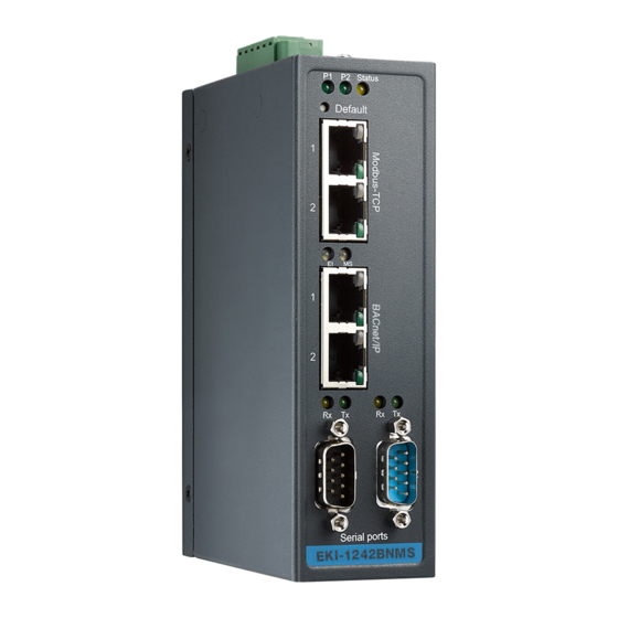
Advantech EKI-1242 Series User Manual (68 pages)
Modbus RTU/TCP to BACnet IP/MSTP, EtherCAT, EtherNet/IP, PROFINET, OPC UA Fieldbus Gateway
Brand:
Advantech
| Category:
Gateway
| Size: 5.35 MB
Table of Contents
Table of Contents
8
Chapter 1 Product Overview
12
Specifications
13
Hardware Views
14
Front View
14
Figure 1.1 Front View
14
Figure 1.2 Front View
16
Figure 1.3 Front View
18
Figure 1.4 Front View
19
Figure 1.5 Front View
21
Rear View
22
Figure 1.6 Rear View
22
Top View
23
Figure 1.7 Top View
23
Figure 1.8 Top View (EKI-1242BNMS/EKI-1242IBNMS)
23
Bottom View
24
Dimensions
24
Figure 1.9 Bottom View
24
Chapter 2 Fieldbus Gateway Installation
27
Installation Guidelines
28
Connecting Hardware
28
Verifying Fieldbus Gateway Operation
28
Installing the Fieldbus Gateway
29
DIN Rail Mounting
29
Figure 2.1 Installing the DIN-Rail Mounting Kit
29
Figure 2.2 Correctly Installed DIN Rail Kit
30
Figure 2.3 Removing the DIN-Rail
30
Wall-Mounting
31
Figure 2.4 Installing Wall Mount Plates
31
Figure 2.5 Wall Mounting Screw Dimensions
32
Figure 2.6 Wall Mount Installation
32
Connecting the Fieldbus Gateway to Ethernet Ports
33
RJ45 Ethernet Cable Wiring
33
Serial Connection
33
Figure 2.7 Ethernet Plug & Connector Pin Position
33
Figure 2.8 DB 9 Pin Position
33
Microsd Card Installation
34
Installing a Microsd Card
34
Figure 2.9 Removing the Component Cover Screw
34
Figure 2.10 Opening the Component Cover
34
Figure 2.11 Installing the Microsd Card
34
Utilizing a Microsd Card
35
Figure 2.12 Closing the Component Cover
35
Figure 2.13 Installing the Component Cover Screw
35
Power Supply Installation
36
Overview
36
Figure 2.14 Power Wiring for EKI-1242 Series
36
Considerations
37
Grounding the Device
37
Wiring a Relay Contact
38
Figure 2.15 Grounding Connection
38
Figure 2.16 Terminal Receptor: Relay Contact
38
Figure 2.17 Terminal Receptor: Relay Contact (EKI-1242BNMS/EKI-1242IBNMS)
38
Wiring the Power Inputs
39
Figure 2.18 Terminal Receptor: Power Input Contacts
39
Figure 2.19 Terminal Receptor: Relay Contact (EKI-1242BNMS/EKI-1242IBNMS)
39
Figure 2.20 Removing a Terminal Block
39
Default Button
40
Figure 2.21 Installing DC Wires in a Terminal Block
40
Figure 2.22 Securing a Terminal Block to a Receptor
40
Chapter 3 Managing Fieldbus Gateway
41
Log in
42
Changing Default Password
42
Figure 3.1 Login Screen
42
Figure 3.2 Changing a Default Password
42
Overview
43
Device Information
43
Figure 3.3 Overview > Device Information > System
43
Figure 3.4 Overview > Device Information > Modbus/Tcp
43
Diagnose
44
Figure 3.5 Overview > Device Information > Bacnet/Ip | Ethernet/Ip | PROFINET | OPC UA
44
Data View
45
Figure 3.6 Overview > Data View
45
Figure 3.7 Overview > Data View
46
Figure 3.8 Overview > Data View
47
Figure 3.9 Overview > Data View
48
Figure 3.10 Overview > Data View
49
Network Setting
50
IP Setting
50
Figure 3.11 Network Setting > IP Setting
50
Figure 3.12 Network Setting > IP Setting
51
Figure 3.13 Network Setting > IP Setting
52
Figure 3.14 Network Setting > IP Setting
53
Figure 3.15 Network Setting > IP Setting
54
Serial Settings
55
Port
55
Figure 3.16 Serial Settings > Port 1/Port 2
55
Protocol Setting
56
Bacnet Setting
56
Figure 3.17 Serial Settings > Port 1
56
Figure 3.18 Protocol Setting > Bacnet Setting
56
Ethercat Setting
57
Ethernet/Ip Setting
57
Figure 3.19 Protocol Setting > Ethercat Setting
57
Figure 3.20 Protocol Setting > Ethernet/Ip Setting
57
PROFINET Setting
58
Figure 3.21 Protocol Setting > PROFINET Setting
58
OPC UA Setting
59
Figure 3.22 Protocol Setting > OPC UA Setting
59
Modbus Setting
60
Figure 3.23 Protocol Setting > Modbus Setting
60
Figure 3.24 Protocol Setting > Modbus Setting > Add
61
Mapping Overview
63
System Management
64
Change Password
64
Backup Manager
64
Figure 3.25 System Management > Change Password
64
Figure 3.26 System Management > Backup Manager > Backup Manager
64
Upgrade Manager
65
Reset System
65
Reboot Device
65
Figure 3.27 System Management > Backup Manager > SD Card Backup
65
Figure 3.28 System Management > Upgrade Manager
65
Figure 3.29 System Management > Reset System
65
Apply Configuration
66
Figure 3.30 System Management > Reboot Device
66
Figure 3.31 System Management > Apply Configuration
66
Tools
67
Modbus Traffic Catcher
67
Figure 3.32 Tools > Modbus Traffic Catcher
67
Advertisement
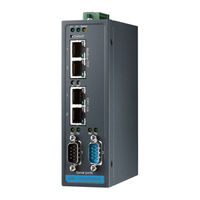
Advantech EKI-1242 Series User Manual (64 pages)
Modbus RTU/TCP to BACnet IP/MSTP | EtherCAT | EtherNet/IP | PROFINET Fieldbus Gateway
Brand:
Advantech
| Category:
Gateway
| Size: 5.12 MB
Table of Contents
Table of Contents
8
Chapter 1 Product Overview
12
Specifications
13
Hardware Views
14
Front View
14
Figure 1.1 Front View (EKI-1242BNMS/EKI-1242IBNMS)
14
Figure 1.2 Front View (EKI-1242ECMS/EKI-1242IECMS)
15
Figure 1.3 Front View (EKI-1242EIMS/EKI-1242IEIMS)
16
Figure 1.4 Front View (EKI-1242PNMS/EKI-1242IPNMS)
17
Rear View
18
Top View
18
Figure 1.5 Rear View
18
Figure 1.6 Top View
18
Bottom View
19
LED Indicators
19
Figure 1.7 Top View ((EKI-1242BNMS/EKI-1242IBNMS)
19
Figure 1.8 Bottom View
19
Dimensions
23
Chapter 2 Fieldbus Gateway Installation
25
Installation Guidelines
26
Connecting Hardware
26
Verifying Fieldbus Gateway Operation
26
Installing the Fieldbus Gateway
27
DIN Rail Mounting
27
Figure 2.1 Installing the DIN-Rail Mounting Kit
27
Figure 2.2 Correctly Installed DIN Rail Kit
28
Figure 2.3 Removing the DIN-Rail
28
Wall-Mounting
29
Figure 2.4 Installing Wall Mount Plates
29
Figure 2.5 Wall Mounting Screw Dimensions
30
Figure 2.6 Wall Mount Installation
30
Connecting the Fieldbus Gateway to Ethernet Ports
31
RJ45 Ethernet Cable Wiring
31
Serial Connection
31
Figure 2.7 Ethernet Plug & Connector Pin Position
31
Figure 2.8 DB 9 Pin Position
31
Microsd Card Installation
32
Installing a Microsd Card
32
Figure 2.9 Removing the Component Cover Screw
32
Figure 2.10 Opening the Component Cover
32
Figure 2.11 Installing the Microsd Card
32
Utilizing a Microsd Card
33
Figure 2.12 Closing the Component Cover
33
Figure 2.13 Installing the Component Cover Screw
33
Power Supply Installation
34
Overview
34
Figure 2.14 Power Wiring for EKI-1242 Series
34
Considerations
35
Grounding the Device
35
Wiring a Relay Contact
36
Figure 2.15 Grounding Connection
36
Figure 2.16 Terminal Receptor: Relay Contact
36
Figure 2.17 Terminal Receptor: Relay Contact (EKI-1242BNMS/EKI-1242IBNMS)
36
Wiring the Power Inputs
37
Figure 2.18 Terminal Receptor: Power Input Contacts
37
Figure 2.19 Terminal Receptor: Relay Contact (EKI-1242BNMS/EKI-1242IBNMS)
37
Figure 2.20 Removing a Terminal Block
37
Reset Button
38
Figure 2.21 Installing DC Wires in a Terminal Block
38
Figure 2.22 Securing a Terminal Block to a Receptor
38
Chapter 3 Managing Fieldbus Gateway
39
Log in
40
Changing Default Password
40
Figure 3.1 Login Screen
40
Figure 3.2 Changing a Default Password
40
Overview
41
Device Information
41
Figure 3.3 Overview > Device Information > System
41
Figure 3.4 Overview > Device Information > Modbus/Tcp
41
Figure 3.5 Overview > Device Information > Bacnet/Ip
42
Figure 3.6 Overview > Device Information > Ethernet/Ip
42
Diagnose
43
Figure 3.7 Overview > Device Information > PROFINET
43
Data View
44
Figure 3.8 Overview > Data View
44
Figure 3.9 Overview > Data View
45
Figure 3.10 Overview > Data View
46
Figure 3.11 Overview > Data View
47
Network Setting
48
IP Setting
48
Figure 3.12 Network Setting > IP Setting
48
Figure 3.13 Network Setting > IP Setting
49
Figure 3.14 Network Setting > IP Setting
50
Figure 3.15 Network Setting > IP Setting
51
Serial Settings
52
Port
52
Figure 3.16 Serial Settings > Port 1/Port 2
52
Protocol Setting
53
Bacnet Setting
53
Figure 3.17 Serial Settings > Port 1
53
Figure 3.18 Protocol Setting > Bacnet Setting
53
Ethercat Setting
54
Ethernet/Ip Setting
54
Figure 3.19 Protocol Setting > Ethercat Setting
54
Figure 3.20 Protocol Setting > Ethernet/Ip Setting
54
PROFINET Setting
55
Figure 3.21 Protocol Setting > PROFINET Setting
55
Modbus Setting
56
Figure 3.22 Protocol Setting > Modbus Setting
56
Figure 3.23 Protocol Setting > Modbus Setting > Add
57
Mapping Overview
59
System Management
60
Change Password
60
Backup Manager
60
Figure 3.24 System Management > Change Password
60
Figure 3.25 System Management > Backup Manager > Backup Manager
60
Upgrade Manager
61
Reset System
61
Reboot Device
61
Figure 3.26 System Management > Backup Manager > SD Card Backup
61
Figure 3.27 System Management > Upgrade Manager
61
Figure 3.28 System Management > Reset System
61
Apply Configuration
62
Figure 3.29 System Management > Reboot Device
62
Figure 3.30 System Management > Apply Configuration
62
Tools
63
Modbus Traffic Catcher
63
Figure 3.31 Tools > Modbus Traffic Catcher
63
Advertisement
Related Products
Advantech EKI-1242ECMS
Advantech EKI-1242IECMS
Advantech EKI-1242IPNMS
Advantech EKI-1242EIMS
Advantech EKI-1242IEIMS
Advantech EKI-1242PNMS
Advantech EKI-1242NR Series
Advantech EKI-1242IEIMS-A
Advantech EKI-1242IECMS-A
Advantech EKI-1242OUMS
Advantech Categories
Motherboard
Computer Hardware
Desktop
Network Router
Touch Panel
More Advantech Manuals
Login
Sign In
OR
Sign in with Facebook
Sign in with Google
Upload manual
Upload from disk
Upload from URL