
Related Manuals for Advantech EKI-1242OUMS


Summary of Contents for Advantech EKI-1242OUMS
- Page 1 User Manual EKI-1242 Series Modbus RTU/TCP to BACnet IP/MSTP | EtherCAT | EtherNet/IP | PROFINET | OPC UA Fieldbus Gateway...
- Page 2 No part of this manual may be reproduced, copied, translated or transmitted in any form or by any means without the prior written permission of Advantech Co., Ltd. Information provided in this manual is intended to be accurate and reliable.
- Page 3 Technical Support and Assistance Visit the Advantech web site at www.advantech.com/support where you can find the latest information about the product. Contact your distributor, sales representative, or Advantech's customer service center for technical support if you need additional assistance.
- Page 4 To assist us in making improvements to this manual, we would welcome comments and constructive criticism. Please send all such - in writing to: support@advantech.com Packing List Before setting up the system, check that the items listed below are included and in good condition.
- Page 5 The sound pressure level at the operator's position according to IEC 704-1:1982 is no more than 70 dB (A). DISCLAIMER: This set of instructions is given according to IEC 704-1. Advantech disclaims all responsibility for the accuracy of any statements contained herein. ...
- Page 6 CAUTION: FOR USE IN A CONTROLLED ENVIRONMENT. REFER TO MANUAL FOR ENVIRONMENTAL CONDITIONS. ATTENTION : POUR UTILISATION EN ATMOSPHÈRE CONTRÔLÉE. CONSULTER LA NOTICE TECHNIQUE. WARNING: EKI-1242 IS LIVE. RISK OF ELECTRIC SHOCK. DISCONNECT POWER BEFORE SERVICING. AVERTISSEMENT : EKI-1242 EST SOUS TENSION. RISQUE DE CHOC ÉLECTRIQUE, COUPER LE COURANT AVANT L'ENTRETIEN.
- Page 7 Safety Precaution - Static Electricity Static electricity can cause bodily harm or damage electronic devices. To avoid damage, keep static-sensitive devices in the static-protective packaging until the installation period. The following guidelines are also recommended: Wear a grounded wrist or ankle strap and use gloves to prevent direct contact with the device before servicing the device.
-
Page 8: Table Of Contents
Contents Chapter Product Overview ........1 Specifications .................... 2 Hardware Views ..................3 1.2.1 Front View..................3 1.2.2 Rear View ................... 11 1.2.3 Top View ..................12 1.2.4 Bottom View................13 Dimensions ..................... 13 Chapter Fieldbus Gateway Installation ..16 Installation Guidelines ................17 2.1.1 Connecting Hardware .............. - Page 9 3.6.2 Backup Manager................. 53 3.6.3 Upgrade Manager............... 54 3.6.4 Reset System ................54 3.6.5 Reboot Device ................54 3.6.6 Apply Configuration ..............55 Tools ....................... 56 3.7.1 Modbus Traffic Catcher .............. 56 EKI-1242 Series User Manual...
- Page 10 List of Figures Figure 1.1 Front View ........................3 Figure 1.2 Front View ........................5 Figure 1.3 Front View ........................7 Figure 1.4 Front View ........................8 Figure 1.5 Front View ........................10 Figure 1.6 Rear View ........................11 Figure 1.7 Top View........................
- Page 11 Figure 3.26 System Management > Backup Manager > Backup Manager........53 Figure 3.27 System Management > Backup Manager > SD Card Backup ........54 Figure 3.28 System Management > Upgrade Manager ..............54 Figure 3.29 System Management > Reset System ................ 54 Figure 3.30 System Management >...
-
Page 12: Chapter 1 Product Overview
Chapter Product Overview... -
Page 13: Specifications
EKI-1242PNMS/EKI-1242IPNMS: 2 x RJ45 + 2 x PROFINET + 2 x RS-232/422/485 EKI-1242OUMS/EKI-1242IOUMS: 2 x RJ45 + 2 x OPC UA + 2 x RS-232/422/485 Power Connector 6-pin removable screw terminal (power & relay) MicroSD Card Configuration backup and restore... -
Page 14: Hardware Views
EKI-1242EIMS/EKI-1242IEIMS: 12~48 V redundant dual power inputs EKI-1242PNMS/EKI-1242IPNMS: 12~48 V redundant dual power inputs EKI-1242OUMS/EKI-1242IOUMS: 12~48 V , redundant dual power inputs Certifications CE, FCC Part 15 Subpart B (Class A) Hardware Views 1.2.1 Front View 1.2.1.1... - Page 15 No. Item Description Serial port DB9 pinout. Port 1 supports BACnet MSTP and port 2 supports RS-232/422/485. LED Indicators LED Name LED Color Description Green Power 1 is ON Power 1 is off or power error condition exists Green Power 2 is ON Power 2 is off or power error condition exists ...
-
Page 16: Figure 1.2 Front View
1.2.1.2 EKI-1242ECMS/EKI-1242IECMS P2 Status Default Serial ports EKI-1242ECMS Figure 1.2 Front View No. Item Description System LED panel See “LED Indicators” on page 5 for further details. Default Press less than 5 seconds to restart the device. Press over 5 seconds to reset to factory default. - Page 17 Catalog LED Name LED Color Description Protocol EtherCAT (EC) Orange Heartbeat: Connect to EtherCAT failed Blinking (500ms ON, 500ms OFF) : EtherCAT is Error-State Green Blinking (200ms ON, 200ms OFF): EtherCAT is PreOP state Blinking (200ms ON, 700ms OFF): EtherCAT is SafeOP state ...
-
Page 18: Figure 1.3 Front View
1.2.1.3 EKI-1242EIMS/EKI-1242IEIMS P2 Status Default Serial ports EKI-1242EIMS Figure 1.3 Front View No. Item Description System LED panel See “LED Indicators” on page 7 for further details. Default Press less than 5 seconds to restart the device. Press over 5 seconds to reset to factory default. -
Page 19: Figure 1.4 Front View
Catalog LED Name LED Color Description Protocol EtherNET/IP (EI) Orange Reserved Green Blinking: IO connection do not establish Solid: IO connection establish Modbus (MS) Orange Blinking: One of Modbus transaction query failed Green Solid: All Modbus transactions query successfully No Modbus transmission Port LED... - Page 20 LED Indicators Catalog LED Name LED Color Description System Green Power 1 is ON Power 1 is off or power error condition exists Green Power 2 is ON Power 2 is off or power error condition exists Status Orange Blinking: System is ready ...
-
Page 21: Figure 1.5 Front View
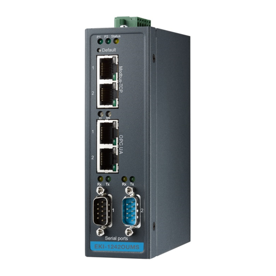
1.2.1.5 EKI-1242OUMS/EKI-1242IOUMS P2 Status Default OU MS Serial ports EKI-1242OUMS Figure 1.5 Front View No. Item Description System LED panel See “LED Indicators” on page 10 for further details. Default Press less than 5 seconds to restart the device. Press over 5 seconds to reset to factory default. -
Page 22: Rear View
Catalog LED Name LED Color Description Protocol OPC UA (OU) Green OPC UA connection establish OPC UA connection do not establish Modbus (MS) Orange Blinking: One of Modbus transaction query failed Green Solid: All Modbus transactions query successfully No Modbus transmission Port LED Serial Orange... -
Page 23: Top View
1.2.3 Top View PWR2 1A@24V PWR1 DC12-48V V2- V2+ V1- V1+ P-Fail Figure 1.7 Top View No. Item Description Wall mounting Screws (x4) used in the installation of a wall mounting plate. screws Terminal block Connect cabling for power and alarm wiring. Ground terminal Screw terminal used to ground chassis. -
Page 24: Bottom View
1.2.4 Bottom View Figure 1.9 Bottom View No. Item Description Wall mounting holes Screws holes (x4) used in the installation of a wall mounting plate Component cover Open to access microSD card port (only supports FAT32 or exFAT file system). Dimensions [1.299] [1.378]... - Page 25 [1.299] [1.378] [0.591] 104 [4.094] 95 [3.740] 42 [1.654] 30.50 [1.201] 40 [1.575] 42 [1.654] 95 [3.740] Figure 1.11 Dimensions (EKI-1242ECMS/EKI-1242IECMS) [1.299] [1.378] [0.591] 104 [4.094] 95 [3.740] 42 [1.654] 30.50 [1.201] 40 [1.575] 42 [1.654] 95 [3.740] Figure 1.12 Dimensions (EKI-1242EIMS/EKI-1242IEIMS) EKI-1242 Series User Manual...
- Page 26 95 [3.740] 42 [1.654] 30.50 [1.201] 40 [1.575] 42 [1.654] 95 [3.740] Figure 1.13 Dimensions (EKI-1242PNMS/EKI-1242IPNMS) [1.299] [1.378] [0.591] 104 [4.094] 95 [3.740] 42 [1.654] 30.50 [1.201] 40 [1.575] 42 [1.654] 95 [3.740] Figure 1.14 Dimensions (EKI-1242OUMS/EKI-1242IOUMS) EKI-1242 Series User Manual...
-
Page 27: Chapter 2 Fieldbus Gateway Installation
Chapter Fieldbus Gateway Installation... -
Page 28: Installation Guidelines
Installation Guidelines The following guidelines are provided to optimize the device performance. Review the guidelines before installing the device. Make sure cabling is away from sources of electrical noise. Radios, power lines, and fluorescent lighting fixtures can interference with the device performance. ... -
Page 29: Installing The Fieldbus Gateway
Installing the Fieldbus Gateway 2.3.1 DIN Rail Mounting The DIN rail mount option is the quickest installation option. Additionally, it optimizes the use of rail space. The metal DIN rail kit is secured to the rear of the fieldbus gateway. The device can be mounted onto a standard 35 mm (1.37”) x 7.5 mm (0.3”) height DIN rail. -
Page 30: Figure 2.2 Correctly Installed Din Rail Kit
See the following figure for an illustration of a completed DIN installation procedure. Figure 2.2 Correctly Installed DIN Rail Kit Grasp the bottom of the fieldbus gateway and slightly rotate it upwards. If there is resistance, the fieldbus gateway is correctly installed. Otherwise, re-attempt the installation process from the beginning. -
Page 31: Wall-Mounting
2.3.2 Wall-Mounting The wall mounting option provides better shock and vibration resistance than the DIN rail vertical mount. Note! When installing, make sure to allow for enough space to properly install the cabling. Before the device can be mounted on a wall, you will need to remove the DIN rail plate. -
Page 32: Figure 2.5 Wall Mounting Screw Dimensions
Once the wall mounting plates are secure on the device, you will need to attach the wall screws (x4). Locate the installation site and place the fieldbus gateway against the wall, making sure it is the final installation location. Use the wall mount plates as a guide to mark the locations of the screw holes. Drill four holes over the four marked locations on the wall, keeping in mind that the holes must accommodate wall sinks in addition to the screws. -
Page 33: Connecting The Fieldbus Gateway To Ethernet Ports
Connecting the Fieldbus Gateway to Ethernet Ports 2.4.1 RJ45 Ethernet Cable Wiring For RJ45 connectors, data-quality, twisted pair cabling (rated CAT5 or better) is recommended. The connector bodies on the RJ45 Ethernet ports are metallic and connected to the GND terminal. For best performance, use shielded cabling. Shielded cabling may be used to provide further protection. -
Page 34: Microsd Card Installation
MicroSD Card Installation The EKI-1242 Series provides an easy way to backup, restore, and deploy configuration settings. The fieldbus gateway provides a microSD card slot to support simple means to manage system configuration settings. Only microSD cards with the FAT32 or exFAT file systems are supported. 2.6.1 Installing a MicroSD Card Before continuing, make sure the file system on the microSD card is set to... -
Page 35: Utilizing A Microsd Card
Close the component cover. Figure 2.12 Closing the Component Cover Secure the component cover with the provided screw. Figure 2.13 Installing the Component Cover Screw 2.6.2 Utilizing a MicroSD Card The device includes a microSD port to provide easy functionality to backup and deployment operations. -
Page 36: Power Supply Installation
Power Supply Installation 2.7.1 Overview Warning! Power down and disconnect the power cord before servicing or wiring the fieldbus gateway. Caution! Do not disconnect modules or cabling unless the power is first switched off. The device only supports the voltage outlined in the type plate. Do not use any other power components except those specifically designated for the fieldbus gateway device. -
Page 37: Considerations
2.7.2 Considerations Take into consideration the following guidelines before wiring the device: The Terminal Block (CN1) is suitable for 12-24 AWG (3.31 - 0.205 mm ). Torque value 7 lb-in. The cross-sectional area of the earthing conductors shall be at least 3.31 mm ... -
Page 38: Wiring A Relay Contact
Electromagnetic Interference (EMI) affects the transmission performance of a device. By properly grounding the device to earth ground through a drain wire, you can set up the best possible noise immunity and emissions. Drain Wire with Lug Connection to Grounding Point Figure 2.15 Grounding Connection By connecting the ground terminal by drain wire to earth ground the fieldbus gateway and chassis can be ground. -
Page 39: Wiring The Power Inputs
2.7.5 Wiring the Power Inputs Caution! Do not disconnect modules or cabling unless the power is first switched off. The device only supports the voltage outlined in the type plate. Do not use any other power components except those specifically designated for the fieldbus gateway device. -
Page 40: Default Button
Insert a small flat-bladed screwdriver in the V1+/V1- wire-clamp screws, and loosen the screws. Insert the negative/positive DC wires into the V+/V- terminals of PW1. If setting up power redundancy, connect PW2 in the same manner. Tighten the wire-clamp screws to secure the DC wires in place. Loosening Securing Wire-clamp... -
Page 41: Chapter 3 Managing Fieldbus Gateway
Chapter Managing Fieldbus Gateway... -
Page 42: Log In
Log In To access the login window, connect the device to the network, see “Connecting the Fieldbus Gateway to Ethernet Ports” on page 22. Once the fieldbus gateway is installed and connected, power on the fieldbus gateway see the following procedures to log into your fieldbus gateway. -
Page 43: Overview
Overview 3.2.1 Device Information The Device Information menu lists information pertaining to the system, such as Model, Firmware version, MAC Address, and more. The information is for review only. To modify the device information, see the respective item within the user interface. -
Page 44: Diagnose
Figure 3.5 Overview > Device Information > BACnet/IP | EtherNet/IP | PROFINET | OPC UA The following table describes the items in the previous figure. Item Description MAC Address Displays the MAC address of the device. Mode Displays the IP address setting mode of the device. IP Address Displays the assigned IP address of the device. -
Page 45: Data View
The ensuing table for Modbus table settings is for reference only: Transaction Name, Connect Status, Read Counter, Write Counter, Connect Error Counter, Read Error Counter and Write Error Counter. The following tables are only available for EKI-1242OUMS/EKI-1242IOUMS. The ensuing table for OPC UA Connection List table settings is for reference only: Index, IP Address and TCP Port. -
Page 46: Figure 3.7 Overview > Data View
The following figure displays the menu as found in the EKI-1242ECMS/EKI- 1242IECMS. Figure 3.7 Overview > Data View The following table describes the items in the previous figure. Item Description Auto Refresh Check the option to automatically have the table refresh the information. -
Page 47: Figure 3.8 Overview > Data View
The following figure displays the menu as found in the EKI-1242EIMS/EKI- 1242IEIMS. Figure 3.8 Overview > Data View The following table describes the items in the previous figure. Item Description Auto Refresh Check the option to automatically have the table refresh the information. -
Page 48: Figure 3.9 Overview > Data View
The following figure displays the menu as found in the EKI-1242PNMS/EKI- 1242IPNMS. Figure 3.9 Overview > Data View EKI-1242 Series User Manual... -
Page 49: Figure 3.10 Overview > Data View
The following figure displays the menu as found in the EKI-1242OUMS/EKI- 1242IOUMS. Figure 3.10 Overview > Data View The following table describes the items in the previous figure. Item Description Auto Refresh Check the option to automatically have the table refresh the information. -
Page 50: Network Setting
Network Setting 3.3.1 IP Setting The IP Setting menu allows you to select a static or DHCP network configuration. The Static displays the configurable settings for the static option. To access this page, click Network Setting > IP Setting. The following figure displays the menu as found in the EKI-1242BNMS/EKI- 1242IBNMS. -
Page 51: Figure 3.12 Network Setting > Ip Setting
Item Description BACnet/IP IP Address Setting Mode Click the drop-down menu to select the IP Address Setting mode: Static address, or DHCP client. IP Address Enter a value to specify the IP address of the interface. The default is 192.168.1.1. Subnet Mask Enter a value to specify the IP subnet mask for the interface. -
Page 52: Figure 3.13 Network Setting > Ip Setting
The following figure displays the menu as found in the EKI-1242EIMS/EKI- 1242IEIMS. Figure 3.13 Network Setting > IP Setting The following table describes the items in the previous figure. Item Description Modbus/TCP IP Address Setting Mode Click the drop-down menu to select the IP address setting mode: Static address, or DHCP client. -
Page 53: Figure 3.14 Network Setting > Ip Setting
Item Description IP Address Enter a value to specify the IP address of the interface. The default is 192.168.1.1. Subnet Mask Enter a value to specify the IP subnet mask for the interface. The default is 255.255.255.0. Gateway Enter a value to specify the default gateway for the interface. The default is 192.168.1.254. -
Page 54: Figure 3.15 Network Setting > Ip Setting
The following figure displays the menu as found in the EKI-1242OUMS/EKI- 1242IOUMS. Figure 3.15 Network Setting > IP Setting The following table describes the items in the previous figure. Item Description Modbus/TCP IP Address Setting Mode Click the drop-down menu to select the IP address setting mode: Static address, or DHCP client. -
Page 55: Serial Settings
To access this page, click Serial Settings > Port 1/Port 2. The following figure displays the menu as found in the EKI-1242BNMS/EKI- 1242IBNMS port 2 (Modbus), EKI-1242ECMS/EKI-1242IECMS, EKI-1242EIMS/EKI- 1242IEIMS, EKI-1242PNMS/EKI-1242IPNMS and EKI-1242OUMS/EKI- 1242IOUMS. Figure 3.16 Serial Settings > Port 1/Port 2 The following table describes the items in the previous figure. -
Page 56: Protocol Setting
The following figure displays the menu as found in the EKI-1242BNMS/EKI- 1242IBNMS port 1 (BACnet). Figure 3.17 Serial Settings > Port 1 The following table describes the items in the previous figure. Item Description Baud Rate Click the drop-down menu to specify the baud rate. The value should conform to the current transmission speeds of connected devices when setting the baud rate. -
Page 57: Ethercat Setting
Item Description Max Info Frames Available under MSTP mode. Enter the variable defining the Max Info Frames setting. The Max Info Frames setting should be high enough to allow for the transmission of at least as many MS/TP frame packets as there are available MS/TP frame buffers. -
Page 58: Profinet Setting
The following table describes the items in the previous figure. Item Description Device Status/ Select Enabled to dedicate the first two I/O mapped bytes for status/ Control Word in I/O control information (default: Enabled). Exception Code in I/ Select Enabled to dedicate the last 64 bytes of data from the O Map EtherNet/IP network stream (default: Enabled). -
Page 59: Opc Ua Setting
3.5.5 OPC UA Setting The OPC UA Setting page is only available for EKI-1242OUMS/EKI-1242IOUMS. On the OPC UA network, the gateway transmits mapped data to the UPC UA nodes. To access this page, click Protocol Setting > OPC UA Setting. -
Page 60: Modbus Setting
3.5.6 Modbus Setting To communicate with remote Modbus/TCP slave devices, specify the Modbus command for each slave device. Each slave device may need more than one command for communication, so it is necessary to add all the commands manually. To access this page, click Protocol Setting > Modbus Setting. Figure 3.23 Protocol Setting >... -
Page 61: Figure 3.24 Protocol Setting > Modbus Setting > Add
To add a new transaction: Figure 3.24 Protocol Setting > Modbus Setting > Add The following table describes the items in the previous figure. Item Description Name Enter the name to identify the transaction, max length: 32 characters. Mode Click the drop-down menu to select Modbus protocol mode: TCP or RTU. - Page 62 Designate the number of read cycles. I/O Map Select Enabled to enable I/O map function (default: Enabled). The function is only available for EKI-1242OUMS/EKI-1242IOUMS. Response Timeout Define the span of time, in milliseconds, within which the server is required to produce a response to the exchange.
-
Page 63: Mapping Overview
The ensuing table for Modbus Client table settings is for reference only: Name, FC, Data Swap, Scan Time, Response Timeout, UID, Read/Write Starting Address, Quantity and When PROFINET doesn't exchange I/O. The following tables are only available for EKI-1242OUMS/EKI-1242IOUMS. The ensuing table for Transaction table settings is for reference only: Name, Data Type, Class, Quantity, Identifier and Access. -
Page 64: System Management
System Management 3.6.1 Change Password The Change Password function allows you to easily update your current password from a single menu. To access this page, click System Management > Change Password. Figure 3.25 System Management > Change Password The following table describes the items in the previous figure. Item Description Password... -
Page 65: Upgrade Manager
Figure 3.27 System Management > Backup Manager > SD Card Backup The following table describes the items in the previous figure. Item Description Automatically Click the radio-button to enable or disable the SD card automatically Backup backup function. Submit Click Submit to save the values and update the screen. 3.6.3 Upgrade Manager The Upgrade Manager page allows you to upgrade firmware. -
Page 66: Apply Configuration
Click Reboot to reboot the fieldbus gateway. Any configuration changes you have made since the last time you issued a save will be lost. Figure 3.30 System Management > Reboot Device 3.6.6 Apply Configuration To access this page, click System Management > Apply Configuration. Click Apply and Reboot to have configuration changes you have made to be saved across a system reboot. -
Page 67: Tools
Tools 3.7.1 Modbus Traffic Catcher The Modbus Traffic Catcher page shows only data sent and received by Modbus. To access this page, click Tools > Modbus Traffic Catcher. Figure 3.32 Tools > Modbus Traffic Catcher The following table describes the items in the previous figure. Item Description Start... - Page 68 No part of this publication may be reproduced in any form or by any means, electronic, photocopying, recording or otherwise, without prior written permission of the publisher. All brand and product names are trademarks or registered trademarks of their respective companies. © Advantech Co., Ltd. 2018...
Need help?
Do you have a question about the EKI-1242OUMS and is the answer not in the manual?
Questions and answers