Table of Contents
Advertisement
Quick Links
Advertisement
Table of Contents

Related Manuals for Advantech EKI-1242PNMS


Summary of Contents for Advantech EKI-1242PNMS
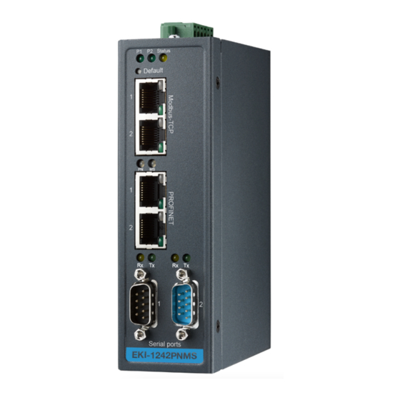
- Page 1 Protocol Gateway EKI-1242PNMS Quick Guide v1.0 2017/10/26...
-
Page 2: Software Specification
1 Induction 1.1 Overview Advantech EKI-1242PNMS is a protocol gateway that provides users with the following software features: Gateway function to transfer data between Modbus TCP/RTU and PROFINET I/O mapped command status and exception code WEB-based GUI for I/O data visualization ... -
Page 3: Network Setting
2 Network Setting The IP Settings menu allows you to select a static address or DHCP network configuration. The Static address displays the configurable settings for the static option. To access this page, click Network Setting > IP Setting Note: The gateway needs to be restarted before any changes will take effect. 3 Serial Setting The Serial Setting allows for the configuration of the serial interface type, baud rate, parity, data/stop bits, and flow control for port configuration. -
Page 4: Protocol Setting
None, XOn/XOff, RTS/CTS. 4 Protocol Setting 4.1 PROFINET Setting On the PROFINET network, the gateway transmits mapped data to PROFINET master though I/O data. The first two I/O mapped bytes in either direction can be dedicated for status/control information, and another 64 bytes of data coming from the Modbus TCP/RTU can feature the Modbus exception codes. - Page 5 Value Description The gateway is in idle state. 0-1 (Least significant bit) The gateway is in running state. 2-15 (reserved) Unused 4.1.2 Exception Code The except code feature gives the scanner on the PROFINET network the opportunity to continuously see and monitor the status of each individual Modbus request on the Modbus TCP/RTU network.
-
Page 6: Modbus Setting
4.2 Modbus Setting On the Modbus TCP/RTU network side, the gateway will act as a Modbus TCP/RTU master. The gateway provides an internal memory for data exchange between Modbus TCP/RTU and PROFINET. For each Modbus read/write command, specify the internal memory address for data exchange. For the read command, the information received from remote slave device will be updated to the specified internal memory address. -
Page 7: Modbus Command
word. Modbus Commands Table A detail list of Modbus TCP/RTU commands in the configuration. The Add, Edit, Delete and Copy buttons support the Modbus command arrangement. To add a new command or modify the existing one, click the Add button or Edit button and Modbus command page will appear. - Page 8 Parameter Description Name A name to help identify the command. The mode of Modbus protocol, TCP or RTU. Mode TCP: Modbus TCP communication over TCP/IP networking. RTU: Modbus RTU communication via serial port. The IP address of remote slave device. The field is available only Slave IP Address in TCP mode.
-
Page 9: Mapping Overview
Decides in what order the different bytes of the received/transmitted data shall be sent on the network. None: Don't need to swap Word: 0x01, 0x02 becomes 0x02, 0x01 Double Word: 0x01, 0x02, 0x03, 0x04 becomes 0x04, 0x03, 0x02, 0x01 Data Swap Note: 1) When function code is 1, 2, 5, or 15, None is the only option. - Page 10 order: Input Data Data from the Modbus TCP/RTU network to the PROFINET network. Status word (optional) Exception code (optional) Input data Output data Data from the PROFINET network to the Modbus TCP/RTU network. Control word (optional) ...
-
Page 11: System Management
5 System Management 5.1 Change Password The Change Password page allows you to modify the password of the gateway. To access this page, click System Management > Change Password. 5.2 Backup Manager The Backup Manager page allows you to backup configuration from gateway or restore configuration file to gateway. -
Page 12: Reset System
5.4 Reset System Click Restore to Defaults button to have all configuration parameters reset to their factory default values. All changes that have been made will be lost. Reset settings take effect after a system reboot. To access this page, click System Management > Reset System. 5.5 Reboot Device Click Reboot Device button to reboot the gateway. -
Page 13: Modbus Traffic Catcher
To access this page, click System Management > Apply Configuration. Please note that changes made to the configuration will not be saved and used by the gateway until they have been applied and system reboot. Remember to apply the configuration in order for changes to take effect. As soon as you have submitted data to the configuration but not yet applied it, you will see the box below at the top of the web pages: 6 Tools... - Page 14 7 microSD Card Functionality The EKI-1242PNMS provides user with an easy way to backup/copy/replacement/deployment. The gateway is equipped with a microSD card slot. User can plug in a microSD card to backup data including the system configuration setting, GSD files, and system data log.
- Page 15 card is empty). Power on the gateway. The settings of gateway will be copied to the microSD card /config/<Model Name>.cfg. Manually configure the gateway via WEB, and all the stored changes will copy to the microSD card for synchronization. Restore the gateway with a microSD card containing a configuration file 1.
- Page 16 Do NOT power off the gateway when loading default settings.
Need help?
Do you have a question about the EKI-1242PNMS and is the answer not in the manual?
Questions and answers