
Subscribe to Our Youtube Channel
Related Manuals for Advantech EKI-1221IEIMB


Summary of Contents for Advantech EKI-1221IEIMB
- Page 1 User Manual EKI-1221IEIMB EKI-1221IPNMB Modbus TCP to PROFINET | EtherNet/IP Protocol Gateway...
- Page 2 No part of this manual may be reproduced, copied, translated or transmitted in any form or by any means without the prior written permission of Advantech Co., Ltd. Information provided in this manual is intended to be accurate and reliable. How- ever, Advantech Co., Ltd.
-
Page 3: Declaration Of Conformity
This product has passed the CE test for environmental specifications when shielded cables are used for external wiring. We recommend the use of shielded cables. This kind of cable is available from Advantech. Please contact your local supplier for ordering information. -
Page 4: Packing List
1 x eAutomation Industrial Communication CD-ROM with User manual 2 x Wall Mounting Bracket and Screws 1 x DIN-rail Mounting Bracket and Screws 1 x EKI-1221IEIMB | PNMB Startup Manual 1 x DC Jack Cable φ2.0/150mm EKI-1221IEIMB | PNMB User Manual... -
Page 5: Safety Instructions
SHOULD BE IN A CONTROLLED ENVIRONMENT. CAUTION: DANGER OF EXPLOSION IF BATTERY IS INCORRECTLY REPLACED. REPLACE ONLY WITH THE SAME OR EQUIVALENT TYPE RECOMMENDED BY THE MANUFACTURER, DISCARD USED BATTERIES ACCORDING TO THE MANUFACTURER'S INSTRUCTIONS. EKI-1221IEIMB | PNMB User Manual... - Page 6 Technical Support and Assistance Visit the Advantech web site at www.advantech.com/support where you can find the latest information about the product. Contact your distributor, sales representative, or Advantech's customer service center for technical support if you need additional assistance.
-
Page 7: About This Manual
This user manual is intended to guide professional installers in installing and config- uring the Protocol Gateway. It includes technical specifications, software utility intro- duction, as well as procedures for the use of the software utility to self-manage the devices. EKI-1221IEIMB | PNMB User Manual... -
Page 8: Table Of Contents
3.6.1 Change Password............... 29 3.6.2 Backup Manager................. 30 3.6.3 Upgrade Manager ............... 30 3.6.4 Reset System................30 3.6.5 Reboot Device ................31 3.6.6 Apply Configuration..............31 Tools ....................... 32 3.7.1 Modbus Traffic Catcher............... 32 EKI-1221IEIMB | PNMB User Manual viii... - Page 9 Figure 2.11 Wall Mount Installation ....................13 Figure 2.12 Ethernet Plug & Connector Pin Position..............14 Figure 2.13 Power Wiring for EKI-1221IEIMB | PNMB ..............15 Figure 3.1 Default Login Screen ....................17 Figure 3.2 Default Login Screen ....................17 Figure 3.3...
-
Page 10: Chapter 1 Overview
Chapter Overview... -
Page 11: Introduction
The EKI-1221 series are industrial protocol gateways that provide seamless communication between Fieldbus and Industrial Ethernet, which enables the integration of new and existing Modbus TCP devices to Ethernet/IP (EKI-1221IEIMB) or Modbus TCP devices to PROFINET (EKI-1221IPNMB) networks. The EKI-1221... -
Page 12: Device Specifications
10/100 Mbps, auto MDI/MDIX Port Connector 8-pin RJ45 Protection Built-in 1.5 KV magnetic isolation Power Power 5.2W Consumption Power Input 12 ~ 48 V , redundant dual inputs Regulatory CE, FCC Part 15 Subpart B (Class A) Approvals EKI-1221IEIMB | PNMB User Manual... -
Page 13: Chapter 2 Getting Started
Chapter Getting Started... -
Page 14: Hardware Overview
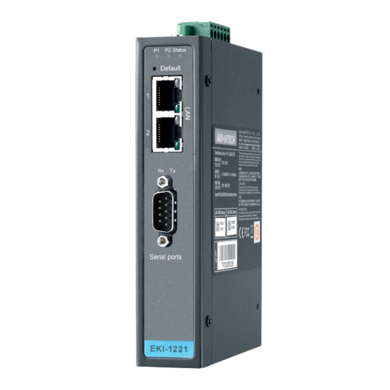
Hardware Overview 2.1.1 Front View The following depicts the EKI-1221IEIMB. P2 Status Default EKI-1221IEIMB Figure 2.1 Front View No. Item Description System LED panel See “LED Indicators” on page 8 for further details. Default button Press for at least 10 seconds to reset device to default settings. -
Page 15: Figure 2.2 Front View
See “LED Indicators” on page 8 for further details. Default button Press for at least 10 seconds to reset device to default settings. ETH port RJ45 port for PROFINET. ETH port RJ45 port for Modbus/TCP. Serial port No available for this model. EKI-1221IEIMB | PNMB User Manual... -
Page 16: Rear View
The following depicts the top view for all models. Figure 2.4 Top View No. Item Description Ground terminal Screw terminal used to ground chassis. Terminal block Connect cabling for power and alarm wiring, see “Power Connec- tion” on page 14. EKI-1221IEIMB | PNMB User Manual... -
Page 17: Led Indicators
Status Amber EKI-1221IEIMB: EtherNet/IP I/O connection is established. EKI-1221IPNMB: System is ready. Amber, blink- EKI-1221IEIMB: System is ready (1 cycle/sec.). EKI-1221IPNMB: Trigger by PROFINET utility's identify function to indicate the device location. System is not working 2.1.5 Dimensions The following view applies to EKI-1221IEIMB. -
Page 18: Figure 2.6 Eki-1221Ipnmb Dimensions
The following view applies to EKI-1221IPNMB. [1.299] [1.378] [0.591] 104 [4.094] 95 [3.740] 36.60 [1.441] 30.50 36.60 [1.441] [1.201] [1.575] EKI-1221IPNMB EKI-1221IPNMB 95 [3.740] Figure 2.6 EKI-1221IPNMB Dimensions EKI-1221IEIMB | PNMB User Manual... -
Page 19: Connecting Hardware
Insert the top back of the mounting bracket over the DIN rail. Push the bottom of the device towards the DIN rail until it snaps into place. DIN Rail Figure 2.7 Installing the DIN-Rail Mounting Kit EKI-1221IEIMB | PNMB User Manual... -
Page 20: Figure 2.8 Removing The Din-Rail
Rotate the bottom of the device towards you and away from the DIN rail. Once the bottom is clear of the DIN rail, lift the device straight up to unhook it from the DIN rail. DIN Rail Figure 2.8 Removing the DIN-Rail EKI-1221IEIMB | PNMB User Manual... -
Page 21: Figure 2.9 Installing Wall Mount Plates
Use the wall mount plates as a guide to mark the locations of the screw holes. Drill four holes over the four marked locations on the wall, keeping in mind that the holes must accommodate wall sinks in addition to the screws. Insert the wall sinks into the walls. EKI-1221IEIMB | PNMB User Manual... -
Page 22: Figure 2.10 Wall Mounting Screw Dimensions
Install the wall mount plate on the screws and slide it forward to lock in place, see the following figure. Figure 2.11 Wall Mount Installation Once the device is installed on the wall, tighten the screws to secure the device. EKI-1221IEIMB | PNMB User Manual... -
Page 23: Ethernet Connection
Caution! Disconnect the power cord before installation or cable wiring. The EKI-1221IEIMB | PNMB supports dual 12 to 48 VDC power inputs and power-fail relay output. EKI-1221IEIMB | PNMB User Manual... -
Page 24: Figure 2.13 Power Wiring For Eki-1221Ieimb | Pnmb
Load Power Figure 2.13 Power Wiring for EKI-1221IEIMB | PNMB You can connect an alarm indicator, buzzer or other signaling equipment through the relay output. The relay opens if power input 1 or 2 fails. In a wiring example where an LED is connected to the relay output, the LED would be off in an Open state. -
Page 25: Chapter 3 Web Interface
Chapter Web Interface... -
Page 26: Overview
Launch your web browser on the PC. In the browser’s address bar, type the device’s default IP address (EKI- 1221IEIMB: Modbus/TCP: 192.168.1.1 Ethernet/IP: 192.168.1.1; EKI- 1221IPNMB: Modbus/TCP:192.168.1.1 PROFINET: 0.0.0.0). The main interface window displays. Figure 3.2 Default Login Screen EKI-1221IEIMB | PNMB User Manual... -
Page 27: Overview
Displays the accumulated time for continuous operation. Modbus/TCP MAC Address Displays the MAC address of the device. Mode Displays the IP address setting mode of the device. IP Address Displays the assigned IP address of the device. EKI-1221IEIMB | PNMB User Manual... -
Page 28: Diagnose
Subnet Mask Displays the assigned subnet mask of the device. Gateway Displays the assigned gateway of the device. EtherNet/IP (Previous figure represent the EKI-1221IEIMB UI, PROFINET not displayed in previous figure) MAC Address Displays the MAC address of the device. -
Page 29: Data View
The function is available in both the EKI-1221IEIMB and the EKI-1221IPNMB devices. The following figure displays the Data View menu as found in the EKI-1221IEIMB. To access this page, click Overview > Data View. Figure 3.5 Overview > Data View (EKI-1221IEIMB) The following table describes the items in the previous figure. -
Page 30: Figure 3.6 Overview > Data View (Eki-1221Ipnmb)
The following figure displays the Data View menu as found in the EKI-1221IPNMB. To access this page, click Overview > Data View. Figure 3.6 Overview > Data View (EKI-1221IPNMB) EKI-1221IEIMB | PNMB User Manual... -
Page 31: Network Setting
EtherNet/IP. Use two different IP subnet when the option is use the same IP unchecked. address setting (EKI-1221IEIMB only) EtherNet/IP IP Address Setting (EKI-1221IEIMB only) Mode Click the drop-down menu to select the IP Address Setting mode: Static address, or DHCP client. EKI-1221IEIMB | PNMB User Manual... -
Page 32: Protocol Setting
64 bytes of data coming from the Modbus/ TCP network can feature the Modbus exception codes. The EtherNet/IP Setting page is only available for EKI-1221IEIMB. To access this page, click Protocol Setting > EtherNet/IP Setting. Figure 3.8 Protocol Setting > EtherNet/IP Setting The following table describes the items in the previous figure. -
Page 33: Profinet Setting
Enable to use the Modbus exception code setting, see Device Status/Control Word in Slot in previous definition. Enter the value for the SNMP Read/Write Community string Read / Write Community (default: Public). Submit Click Submit to save the values and update the screen. EKI-1221IEIMB | PNMB User Manual... -
Page 34: Modbus/Tcp Setting
Click Add to add a new transaction. Transactions represent the data that is read from/written to the servers of the Modbus-TCP network. Edit Click Edit to modify existing transactions. Delete Click Delete to delete existing transactions. Copy Click Copy to copy an existing transaction. EKI-1221IEIMB | PNMB User Manual... -
Page 35: Figure 3.11 Protocol Setting > Modbus/Tcp Setting > Add
03: Read holding registers 04: Read input register 05: Write single coil 06: Write single register 15: Write multiple coils 16: Write multiple registers 23: Read/Write multiple registers EKI-1221IEIMB | PNMB User Manual... - Page 36 Write safe value: The value to transmit for each element. Stop: The transmission of any and all data to the Modbus server is halted. Submit Click Submit to save the values and update the screen. Back Click Back to return the previous page. EKI-1221IEIMB | PNMB User Manual...
-
Page 37: Mapping Overview
The Mapping Overview function allows the viewing of data between Modbus TCP to PROFINET Slot or Modbus TCP to EtherNet/IP. The following figure displays the Data View menu as found in the EKI-1221IEIMB. To access this page, click Protocol Setting > Mapping Overview. -
Page 38: System Management
If you want to disable the password protection, change the password to the default option None (leave the password column blank). Be sure apply and reboot the system (System Management > Apply Configuration) to save the updates. EKI-1221IEIMB | PNMB User Manual... -
Page 39: Backup Manager
Click Restore to have all configuration parameters reset to their factory default values. All changes that have been made will be lost, even if you have issued a save. Reset settings take effect after a system reboot. Figure 3.17 System Management > Reset System EKI-1221IEIMB | PNMB User Manual... -
Page 40: Reboot Device
Click Apply and Reboot to have configuration changes you have made to be saved across a system reboot. All changes submitted since the previous save or system reboot will be retained by the device. Figure 3.19 System Management > Apply Configuration EKI-1221IEIMB | PNMB User Manual... -
Page 41: Tools
Click Stop to stop capturing the data. Export Click Export to export and download the captured data. Auto Scroll Check the option to cycle through all of the data screens automatically while start capturing data. EKI-1221IEIMB | PNMB User Manual... - Page 42 No part of this publication may be reproduced in any form or by any means, electronic, photocopying, recording or otherwise, without prior written permis- sion of the publisher. All brand and product names are trademarks or registered trademarks of their respective companies. © 2017 Advantech Co., Ltd.
Need help?
Do you have a question about the EKI-1221IEIMB and is the answer not in the manual?
Questions and answers