
Related Manuals for norbar ET2-72-1000-110


Summary of Contents for norbar ET2-72-1000-110
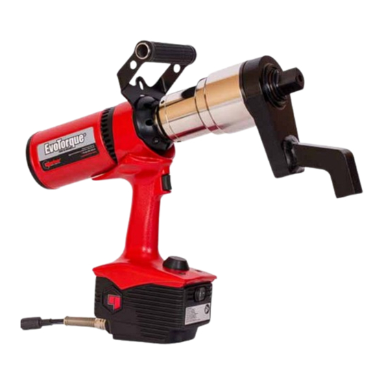
- Page 1 OPERATOR’S MANUAL ® EVOTORQUE Part Number 34426 | Issue 4 | Original Instructions (English)
-
Page 2: Table Of Contents
CONTENTS Part Numbers Covered by This Manual Description Options Serial Number Safety – General Power Tool Safety Warnings Work Area Safety Electrical Safety Personal Safety Power Tool Use and Care Service ® Safety – EvoTorque 2 Specific Safety Warning Markings on Tool ®... -
Page 3: Part Numbers Covered By This Manual
PART NUMBERS COVERED BY THIS MANUAL This manual covers the set up and use of Norbar EvoTorque ® 2 tools. Part Number Model Torque Range 180230.B06 ET2-72-1000-110 100 - 1000 N·m * 180220.B06 ET2-72-1000-230 100 - 1000 N·m * 180231.B06 ET2-72-1350-110 135 –... -
Page 4: Safety - General Power Tool Safety Warnings
SAFETY – GENERAL POWER TOOL SAFETY WARNINGS Symbol Meaning The lightening flash is intended to alert the user to the presence of uninsulated “dangerous voltage” within the products enclosure that may be of sufficient magnitude to constitute a risk of electric shock to persons. The exclamation mark is intended to alert the user to the presence of important operating and maintenance (servicing) instructions in the manual. -
Page 5: Power Tool Use And Care
Use personal protective equipment (PPE). Always wear eye protection. Protective equipment such as a dust mask, non-skid safety shoes, hard hat or hearing protection used for appropriate conditions will reduce personal injuries. Prevent unintentional starting. Ensure the switch is in the off-position before connecting to power source and/or battery pack, picking up or carrying the tool. -
Page 6: Safety - Evotorque
2 tools are supplied without a reaction bar. These tools MUST NOT be used until a suitable reaction bar has been fitted. Norbar define the reaction bar as ‘interchangeable equipment’ under the European directive 2006/42/EC on Machinery Safety. If applicable a new reaction bar will... -
Page 7: Introduction
INTRODUCTION The EvoTorque ® 2 is an electronic torque tool designed for applying torque to threaded fasteners. There are models to cover torque capacities of 1000 N∙m to 7000 N∙m. The unique ‘Intelligent Joint Sensing’ technology will accurately tighten to the correct torque without the risk of excess overshoot or undershoot that is common in other electric tools. -
Page 8: Accessories
Truck and Bus Wheels (1") 19089.012 26969 26970 26970 Carry Case 26969 NOTE: Requires both “Reaction Bar” and “Reaction Bar Adaptor” to be used together. Reactions to suit specific applications can be supplied, contact Norbar or a Norbar distributor for details. -
Page 9: Features And Functions
FEATURES AND FUNCTIONS Drive square Top handle / lifting bracket for safe tool use Reaction bar Cooling Ergonomic trigger control Bluetooth ® Smart Strain housing relief PASS / FAIL User lights interface ON/OFF Mains lead switch FIGURE 1 – Tool Features ... - Page 10 Tool can be locked to 2 different functional levels. Send ‘Log Results’ in real time. Output results in CSV format (USER mode). Factory calibrated to ± 3%. Ability to define pass fail result tolerances. Using patent pending “Intelligent Joint Sensing”...
-
Page 11: Set Up Instructions
SET UP INSTRUCTIONS NOTE: If the equipment is used in a manner not specified by the manufacturer, the protection provided by the equipment may be impaired. WARNING: ALLOW THE TOOL TO EQUALISE TO THE AMBIENT TEMPERATURE / HUMIDITY BEFORE SWITCHING ON. WIPE OFF ANY MOISTURE BEFORE USE. -
Page 12: Torque Reaction
Torque Reaction The reaction bar ensures all reaction forces are contained, so torque reaction is not passed back to the operator. Several reaction bar styles are available. Fit reaction bar as detailed below. Reaction Bar Type Fitting Instructions Cranked Reaction Bar (Standard) Fit reaction bar / plate over the drive square to engage Single Sided Reaction Plate (Option) reaction splines. - Page 13 If an extra long socket is used it may move the reaction bar outside the safe reaction window, as seen in figure 8. The standard reaction bar may need to be extended to ensure it remains within the shaded area. For alternative reaction bars see ACCESSORIES list.
- Page 14 The dimensions of the standard reaction bars are shown in the following table: Steel Reaction Bar (Supplied) Tool ‘L’ ‘A’ ‘B’ ‘W’ ‘SQ’ ET2-72 ¾” or 1” ET2-80 1” ET2-92 1” ET2-119 1 ½” FIGURE 10 – Reaction Bar Blade Nose Extension Tool ‘L’...
- Page 15 ® When the EvoTorque 2 is in operation the reaction bar rotates in the opposite direction to the output drive square and must be allowed to rest squarely against a solid object or surface adjacent to the fastener to be tightened.
-
Page 16: Connecting Supply
Connecting Supply WARNING: THE TOOL HAS BEEN DESIGNED FOR ONE VOLTAGE ONLY. CHECK THAT THE POWER SUPPLY CORRESPONDS TO THE VOLTAGE ON THE TOOL RATING PLATE. WARNING: THE TOOL MUST BE EARTHED ENSURE POWER SUPPLY HAS AN EARTH DO NOT OPERATE WITHOUT AN EARTH WARNING: FOR OPERATOR SAFETY ENSURE THE MAINS SUPPLY HAS A RESIDUAL CURRENT DEVICE (RCD). -
Page 17: Turn On
Turn On Turn on mains supply. Change ON/OFF switch from 0 to I. The logo is shown for 2 seconds: FIGURE 17 – Norbar Logo The capacity is shown for 2 seconds: TIP: Fan operation: During the logo & capacity screens the fan will run to give confirmation that it is working. -
Page 18: Set Up Targets
Set Up Targets Press to exit the Run screen and show the Menu screen. Select and press to view targets. FIGURE 22 – Select Target Set Up Press to highlight required Target # (T01 – T20). Press to enter Target Set Up / edit. FIGURE 23 –... -
Page 19: View / Select Work Group, Work Ids
NOTE: This screen will only be shown if the angle target was ‘0°’ on the Set Angle screen. Press to enable ‘✓’ or disable ‘✘’. When set press to accept. FIGURE 27 – Set Audit Target NOTE: This screen will only be shown if the Audit ‘✓’... -
Page 20: Tool Settings
Tool Settings This menu is used to set or view the Unit, Auto Reset, Lock, Bluetooth ® , Time & Date, Display, Tolerances, Output Format, 2 Stage Target and Operation Direction. FIGURE 31 – Tool Settings Menu FIGURE 33 – Tool Set Up options 1 The Lock screen will appear if ‘Lock’... -
Page 21: View Results
View Results (example screens) Press to exit the Run screen and show the Menu screen. Select and press to view results. FIGURE 35 – Select View Results Press to View Results. Erase all will delete all of the results stored on the tool. FIGURE 36 –... - Page 22 This example screen shows a User ID called ‘John Smith’ that was in use for the following saved results. FIGURE 39 – View User ID This example screen shows a 400 N·m Audit result. FIGURE 40 – View Result Press to display the memory Record #.
-
Page 23: Tool Information
Tool Information Press to select View Tool Information to begin a cycle through tool information screens . The Tool Capacity, Votage and Date/Time will be shown first. (see Figure 43 below). FIGURE 42 – Select View Tool Information Press to continue cycle. The Tool Serial # and Tool Name will then be shown (see Figure 44 below). - Page 24 Press to continue cycle and show the Error Log (see Figure 47 below). ® FIGURE 46 – Bluetooth Smart Press to continue cycle and show the Tool Statistics (see Figure 48 below). FIGURE 47 – View Error Log This screen shows the usage statistics for the tool. Press to continue cycle and show the Tool Usage (see Figure 49 below).
-
Page 25: Operating Instructions
OPERATING INSTRUCTIONS WARNING: KEEP HANDS CLEAR OF THE REACTION BAR. WARNING: WHEN USING THIS TOOL IT MUST BE SUPPORTED AT ALL TIMES IN ORDER TO PREVENT UNEXPECTED RELEASE IN THE EVENT OF FASTENER OR COMPONENT FAILURE. Tightening Fit the tool with the correct size impact or high quality socket to suit fastener. TIP: For added safety it is recommended to secure the socket to the drive square. - Page 26 Joint complete. See colour of displayed value for pass / fail status. FIGURE 52 – Torque Target result (shown as red for fail) FIGURE 53 – Torque & Angle target (with Final Torque) result (shown as green for pass) FIGURE 54 – Audit Torque target result (showing achieved torque and output (bolt) movement in degrees) LED Status Meaning...
-
Page 27: Saving Results
Saving Results Auto Reset = Button Operation (after a successful tightening) Press either the buttons to Save the displayed (joint complete) reading and reset the tool, ready for the next tightening operation. Press the button will reset the tool ready for the next tightening operation without saving the (joint complete) reading. -
Page 28: Maintenance
For optimum performance and safety, regular tool maintenance is required. The user maintenance is limited to that stipulated in this section. Any other maintenance or repairs should be carried out by Norbar or a Norbar distributor. Maintenance intervals will depend on the tool usage and the environment in which it is being used. -
Page 29: Gearbox
Fit new screw. Tighten to 9 N·m (M5). TIP: If the drive square fails continually then seek advice from Norbar or a Norbar distributor. Product Disposal This symbol on the product indicates that it must not be disposed of in the general waste. -
Page 30: Specifications - Evotorque ® 2
® SPECIFICATIONS - EvoTorque Torque Tool Tool Speed* Reaction Case & Part Number (Free Weight Ancillaries Weight Minimum Maximum Running) (kg) (kg) (kg) 180220.B06 / 180230.B06 100 N·m 1000 N·m 21 rpm 10.4 180221.B06 / 180231.B06 135 N·m 1350 N·m 17 rpm 10.4 180222.B08 / 180232.B08... - Page 31 Torque Accuracy: ±3% of target torque on 100° joint for calibrated range (see calibration certificate). Torque Setting: 10% to 100% of tool capacity. Angle Accuracy: ±2°. Angle Setting: 10° to 720°. Angle Start Threshold: 10% to 100% of tool capacity. Display: Colour OLED (160 x 128 pixels) Bluetooth...
-
Page 32: Specifications - Usb Bluetooth Smart Adapter
® SPECIFICATIONS - USB Bluetooth Smart adapter FCC and IC This equipment has been tested and found to comply with the limits for a Class B digital device, pursuant to Part 15 of the FCC Rules. These limits are designed to provide reasonable protection against harmful interference in a residential installation. - Page 33 ® USB Bluetooth Smart adapter is in conformity with the essential requirements and other relevant requirements of the RED Directive (2014/54/EU). South-Korea USB Bluetooth ® Smart adapter is certified in South-Korea with certification number: KCC-CRM-BGT-BLED112 Japan ® USB Bluetooth Smart adapter has MIC Japan type certification with certification number: 003WWA111471 Brazil...
-
Page 34: Declaration Of Conformity
The UKCA mark was first applied in: 2021. Signed for and on behalf of Norbar Torque Tools Ltd. Trevor Mark Lester B.Eng. Signed:... -
Page 35: Trouble Shooting
TROUBLE SHOOTING The following is only a guide, for more complex fault diagnoses please contact Norbar or a Norbar distributor. Problem Likely Reason Likely Solutions No mains power Check electrical mains power is working External fuse or circuit breaker No Display... -
Page 36: Glossary Of Terms
Output Format has been set to Not working with EvoLog Change the Output Format to EvoLog USER Lost PIN number Contact Norbar Battery symbol shown in Contact Norbar power up Decrease Turn Angle setting. a) Turn Angle set too High. - Page 37 NOTES...
- Page 38 Tel + 44 (0)1295 270333 Email enquiry@norbar.com To find your local Norbar For the most up-to-date company or distributor, version of the Operator’s please scan the QR code Manual, please scan the QR below. code below. www.norbar.com © Norbar Torque Tools Ltd 2021...
Need help?
Do you have a question about the ET2-72-1000-110 and is the answer not in the manual?
Questions and answers