Table of Contents
Advertisement
Quick Links
Advertisement
Table of Contents

Subscribe to Our Youtube Channel
Related Manuals for norbar PTM-72 Series


Summary of Contents for norbar PTM-72 Series
- Page 1 72-1000 & 72-2000 STALL TOOLS OPERATORS HANDBOOK (PART NO. 34313) Issue 1 (ENGLISH) NORBAR TORQUE TOOLS LTD, Beaumont Road, Banbury, Oxfordshire, OX16 1XJ, UNITED KINGDOM Tel : + 44 (0) 1295 270333, Fax : + 44 (0) 1295 753643 www.norbar.com...
- Page 3 PAGE 1 OF 16 ISSUE 1 09 2005 CONTENTS PAGE Safety Introduction Features and Functions Set up Instructions Operating Instructions Maintenance Specification Declaration of Conformity Trouble shooting Glossary of terms MODEL NUMBERS COVERED BY MANUAL:- ______________________________________ MAXIMUM PART DIRECTION MODEL TOOL TYPE TORQUE NUMBER...
- Page 4 PAGE 2 OF 16 ISSUE 1 09 2005 SAFETY IMPORTANT: DO NOT OPERATE THE TOOL BEFORE READING THESE INSTRUCTIONS. FAILURE TO DO SO MAY RESULT IN PERSONAL INJURY OR DAMAGE TO THE TOOL. This tool is intended for use with threaded fasteners. Any other use is not recommended. The use of ear protectors is recommended.
-
Page 5: Part Number Description
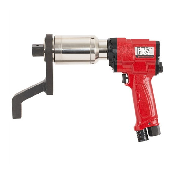
PAGE 3 OF 16 ISSUE 1 09 2005 INTRODUCTION ® The Pneutorque PTM72mm series are air driven power tools designed for applying torque to threaded fasteners. There are models to cover torque capacities of 1000 N.m and 2000 N.m. These models are available in 2 types: Stall Tool These tools use the air pressure set on an external pressure regulator to determine the stall torque. -
Page 6: Features And Functions
PAGE 4 OF 16 ISSUE 1 09 2005 FEATURES AND FUNCTIONS REPLACEABLE DRIVE SQUARE All tools are fitted with either ¾” (19mm) or 1” (25.4mm) drive square that can easily be replaced. TRIGGER The trigger controls the flow of air. The more the trigger is pressed the more air flows into the tool. This allows for slow positioning of socket and reaction plate. - Page 7 PAGE 5 OF 16 ISSUE 1 09 2005 Figure 1 3. If running the tool with oil, check the oil level in the lubricator and fill to the correct level if required. (see MAINTENANCE section) TIP. These tools have been designed to run with a clean, dry, unlubricated air supply if required, but this is not essential.
- Page 8 PAGE 6 OF 16 ISSUE 1 09 2005 TORQUE REACTION ___________________________________________________________ When the Pneutorque® is in operation the reaction arm rotates in the opposite direction to the output drive square and must be allowed to rest squarely against a solid object or surface adjacent to the bolt to be tightened.
- Page 9 PAGE 7 OF 16 ISSUE 1 09 2005 SETTING CLOCKWISE/COUNTER-CLOCKWISE OPERATION _______________________ Clockwise (Arrow towards drive square) Figure 4a Counter-clockwise (Arrow away from drive square) Figure 4b TIP: To help set the clockwise / counter-clockwise operation run the tool in neutral position before re-engaging.
- Page 10 PAGE 8 OF 16 ISSUE 1 09 2005 SETTING TORQUE FOR BOLT TIGHTENING______________________________________ STALL TOOLS ________________________________________________________________ These tools use the air pressure set on an external pressure regulator unit to determine the stall torque. They are supplied with an Air Pressure Graph which relates torque output to air pressure. Set the torque output as follows:- 1.
- Page 11 PAGE 9 OF 16 ISSUE 1 09 2005 NOTE: THE TORQUE REGULATOR WILL NOT GIVE FULL CONTROL OVER THE ENTIRE RANGE OF THE TOOL. THE RANGE OF THE REGULATOR IS FROM FULL TORQUE TO APPROXIMATELY 50% OF FULL TORQUE VALUE. TIP: If a lower torque level is required it may be achieved by reducing the mains air pressure to the tool.
-
Page 12: Operating Instructions
PAGE 10 OF 16 ISSUE 1 09 2005 OPERATING INSTRUCTIONS WARNING: KEEP HANDS CLEAR OF THE REACTION ARM. WARNING: WHEN USING THIS TOOL IT MUST BE SUPPORTED AT ALL TIMES IN ORDER TO PREVENT UNEXPECTED RELEASE IN THE EVENT OF FASTENER OR COMPONENT FAILURE. - Page 13 PAGE 11 OF 16 ISSUE 1 09 2005 B. RELEASING _______________________________________________________________ NOTE: ONLY FOR BI-DIRECTIONAL TOOLS Fit the Pneutorque® with the correct size impact or high quality socket to suit the fastener to be released. Ensure the clockwise/counter-clockwise selector is correctly set. Rotate the handle into a convenient position relative to the reaction arm.
-
Page 14: Maintenance
Any other maintenance or repairs should be carried out by Norbar or a Norbar approved agent and should form part of a service. Service intervals will depend on the type of usage of the tools and the environment in which they are being used. - Page 15 PAGE 13 OF 16 ISSUE 1 09 2005 DRIVE SQUARE:- ______________________________________________________________ To avoid internal damage (especially due to torque overload), the output drive square has been designed to shear first. This saves major internal damage and allows easy square removal. Figure 10 The drive square can be replaced with either a ¾”...
-
Page 16: Specifications
PAGE 14 OF 16 ISSUE 1 09 2005 SPECIFICATIONS RANGE MAXIMUM TOOL SPEED MODEL OVERLOAD (FREE RUNNING AT MAX. AIR PRESSURE) 1000Nm 200 N.m 1000 N.m 1100 N.m 125 r/min 2000Nm 400 N.m 2000 N.m 2200 N.m 60 r/min Repeatability: ±... -
Page 17: Declaration Of Conformity
PAGE 15 OF 16 ISSUE 1 09 2005 Declaration of Conformity Manufactured by Norbar Torque Tools Ltd., Beaumont Road, Banbury, Oxon, OX16 1XJ The Directives covered by this Declaration Safety of Machinery Directive, 98/37/EEC The Equipment Covered by this Declaration Equipment: PTM –... -
Page 18: Troubleshooting
PAGE 16 OF 16 ISSUE 1 09 2005 TROUBLE SHOOTING The following is only a guide, for more complex faults please contact your local Norbar distributor or Norbar directly. PROBLEM LIKELY SOLUTIONS Tool output does not rotate when trigger pulled.
Need help?
Do you have a question about the PTM-72 Series and is the answer not in the manual?
Questions and answers