
Related Manuals for norbar NORTRONIC


Summary of Contents for norbar NORTRONIC
- Page 1 All manuals and user guides at all-guides.com OPERATOR’S MANUAL NORTRONIC ® Part Number 34399 | Issue 4 | Original Instructions (English)
- Page 2 All manuals and user guides at all-guides.com...
-
Page 3: Table Of Contents
All manuals and user guides at all-guides.com Contents Introduction Part Numbers Covered by This Manual Parts Included USB Wireless Adapters (accessory) Software Compatibility Features and Functions Before Use Preparation Battery Fitting / Replacement Ratchet Head Fitting / Replacement Button Functions Measure Display Operation Start Up... - Page 4 All manuals and user guides at all-guides.com Display Multiplier Complete Warnings Torque CRS Data Store View Results Erase All About Specifications EU Declaration of Conformity Maintenance NorTronic ® Calibration Battery Replacement Repair Cleaning Product Disposal Battery Disposal Trouble Shooting Glossary of Terms...
-
Page 5: Introduction
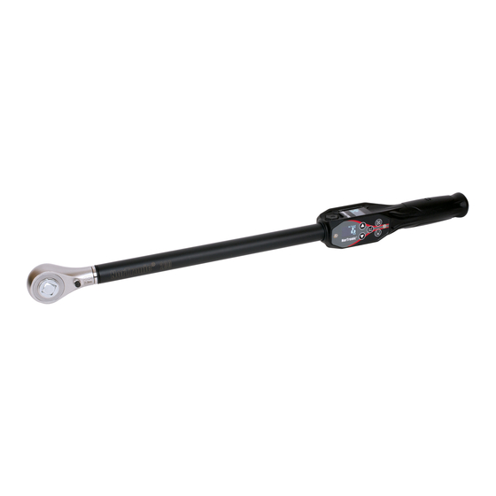
All manuals and user guides at all-guides.com INTRODUCTION The NorTronic is an electronic torque and angle wrench capable of measuring, displaying, storing and ® transmitting test results and receiving configuration settings from TDS (Torque Data System PC software) via the USB or wireless interface. -
Page 6: Features And Functions
2 colour 0.95” OLED displays for visual indication of measurement against Target status. • Audible indication of Target status. • Vibration feedback when Target reached. • 4 digit resolution for all NorTronic ® electronic torque wrenches. • Maximum of 2400 (date & time stamped) reading memory store. •... -
Page 7: Before Use
IMPORTANT: IF THE EQUIPMENT IS USED IN A MANNER NOT SPECIFIED BY THE MANUFACTURER, THE PROTECTION PROVIDED BY THE EQUIPMENT MAY BE IMPAIRED. WARNING: ALLOW THE NORTRONIC TO EQUALISE TO THE AMBIENT ® TEMPERATURE/HUMIDITY BEFORE SWITCHING ON. WIPE OFF ANY MOISTURE BEFORE USE. -
Page 8: Button Functions
I<10% Function Number of readings that have been saved for the current Target. Shows the next peak reading that will be saved to the NorTronic ® (if Auto Reset enabled). Wireless connected to P.C. (TDS). USB connected to P.C. (TDS). -
Page 9: Operation Start Up
® is always powered up or in a deep sleep mode. Upon fitting the batteries and end cap, press any button to wake the NorTronic up from sleep. The Norbar ® logo is displayed for 2 seconds followed by the measure display:... -
Page 10: Peak Reading With Auto Reset
Y / N Tool Target Having already set a Tool Target (see page 13 for more details), the NorTronic beeps as the applied torque ® approaches the Torque Target (starting slow and getting faster) until a continuous tone is heard when the Target has been reached. -
Page 11: Targets - Change
Resume from Sleep (Gyroscope drift calibration) To wake the NorTronic ® , press any button. After the display of the Norbar logo the NorTronic ® will perform a gyroscope drift calibration. The Gyroscope drift calculation will also be done if the temperature changes by more than 3 degrees. -
Page 12: Usb Interface
This screen is displayed during the Gyroscope drift calculation. The NorTronic can now be used. ® NOTE: The Gyro drift calibration will not be done if the NorTronic ® is woken less than 30 seconds after going to sleep. USB Interface The NorTronic can be connected to a PC with TDS installed using the cable supplied. -
Page 13: Wireless Interface
Multiplier The Multiplier value only needs to be changed if a Norbar HT (Hand Torque) Gearbox is being used in conjunction with the NorTronic . This setting ensures the NorTronic displays correct Torque for the ®... -
Page 14: Exit Measure Display (Options Menu)
ABOUT Press to enter Measure. TDS Receive Results Interface Test Results can be sent as they happen (i.e. in real time) from the NorTronic Tool to via the ® Receive Results window using the Wireless interfaces. time. Only... -
Page 15: Tool Target - Setting
• Minimum = 0 (No Target), Maximum = 100% of NorTronic Torque capacity. ® Audit mode ‘ ’ NOTE: This screen will only be shown if Angle is Enabled in SETUP and Target is larger than ✓... -
Page 16: Set Final Target
Options Menu. button is not functional. • Minimum = 0 (No Final Torque Target),, Maximum = NorTronic ® Torque capacity. • If the Final Target value is set to 0, the Final Target is disabled (Torque + Angle Target), if it is set to a... -
Page 17: Tds Target Interface
Target ticked “Set Tool Options” can be changed on the tool unless the “Locked” option has been downloaded to the NorTronic by clicking the Update button on “Set Tool Options” as shown below ® (See page 16 for more information on “Tool... -
Page 18: Tool Setup
All manuals and user guides at all-guides.com TOOL - SETUP All NorTronic Tool - SETUP can be configured in ® downloaded to the tool. NorTronic Tool - SETUP ® includes: Limits, Units, Time & Date, Sleep, Angle Display, Auto Zero, Active From,... -
Page 19: Torque Limits
All manuals and user guides at all-guides.com LIMITS Press to highlight required setting. UNITS DATE / TIME Press to confirm the setting to change. SLEEP Options Menu. Press to exit to the NOTE: Tool - SETUP is a scrolling screen. Press ANGLE the DOWN button with SLEEP highlighted to go to ANGLE etc. -
Page 20: Angle Limits
All manuals and user guides at all-guides.com Angle Limits Angle ? Press to change highlighted value. HI Limit Press to confirm and go to Limit. LO Limit Press to exit to SETUP (saving changes). • Target + HI Limit, Target - LO Limit in degrees (°). •... -
Page 21: Sleep
Sleep if there has been No activity for the time set in ‘Sleep After’. During sleep, ® none of the NorTronic functions operate. ® Sleep After ? Press to change value. Press to confirm and exit to SETUP. -
Page 22: Vibrate
(saving changes). • Node number is an individual identification of a tool on the wireless network. multiple NorTronic ® tools are communicating with the same USB wireless adapter (at the same time), they must each have individual node numbers. •... -
Page 23: Auto Reset
All manuals and user guides at all-guides.com Auto Reset (Hold Time ?) Auto Reset ? Press to change setting. If , pressing will take the user to ‘SETUP Hold Time ?’. If the user will return to SETUP. , •... -
Page 24: Complete
Torque CRS Distance ? 31.8 Press to change value. Press to confirm and go to SETUP (saving changes). • Minimum = 0.1, Maximum = 999.0. Default: - NorTronic 50 & 200 = 31.8 mm, NorTronic 330 = 35.0 mm. ® ®... -
Page 25: Data Store
All manuals and user guides at all-guides.com DATA STORE Data Store Press to change highlighted option. View Results Press to confirm. Erase All Press to go to SETUP. View Results Result Press the buttons to scroll through the Saved 30/03/12 Test Results screen(s). -
Page 26: About
All manuals and user guides at all-guides.com ABOUT Each of the 3 screens (starting with serial #), is displayed for 2 seconds before returning to SETUP. The ‘Extended Capacity’ screen is shown if the ‘Multiplier’, ‘Torque CRS’ or both have been changed from their default values. -
Page 27: Specifications
All manuals and user guides at all-guides.com SPECIFICATIONS Weight Dimensions (mm) Model Resolution Zero Suppression NorTronic ® 0.01 N·m ± 1 L.S.D (0.01 N·m) 1.20 2.63 NorTronic 0.1 N·m ± 1 L.S.D (0.1 N·m) 1.45 3.20 ® NorTronic 0.1 N·m ±... - Page 28 200, 50% of Torque Capacity NorTronic 330, 50% of Torque Capacity ® Directive 1999/5/EC: Norbar hereby declares that this NorTronic (Part # 43500, 43501, ® 43502 & 43503) are in compliance with the essential requirements and other relevant provisions of Directive 1999/5/EC”.
-
Page 29: Eu Declaration Of Conformity
Directives has been compiled by the signatory below and is available for inspection by the relevant enforcement authorities. The CE mark was first applied in: 2014. Signed for and on behalf of Norbar Torque Tools Ltd. Signed: Full Name: Trevor Mark Lester B.Eng. -
Page 30: Maintenance
The coin cell should only be replaced by Norbar or a Norbar approved agent. Repair Repair should be carried out at Norbar or by a Norbar approved agent, where all the facilities to ensure the NorTronic is functioning at maximum accuracy are available. -
Page 31: Trouble Shooting
Tool A reference to the tool being used. Transceiver Internal wireless module to enable data to be transmitted / received by the NorTronic ® Universal Serial Bus. Work identification - the reference to the task, application or job e.g.: a bolted flange, Work Id engine cylinder head, vehicle wheel nuts, etc. - Page 32 Tel + 86 21 6145 0368 Tel + 61 (0)8 8292 9777 Email sales@norbar.com.cn Email enquiry@norbar.com.au NORBAR TORQUE TOOLS INDIA PVT. LTD NORBAR TORQUE TOOLS INC Plot No A-168, Khairne Industrial Area, 36400 Biltmore Place, Willoughby, Thane Belapur Road, Mahape, Ohio, 44094 Navi Mumbai –...
Need help?
Do you have a question about the NORTRONIC and is the answer not in the manual?
Questions and answers