Table of Contents
Advertisement
Quick Links
Advertisement
Table of Contents

Related Manuals for norbar PNEUTORQUE PTME-72-1000


Summary of Contents for norbar PNEUTORQUE PTME-72-1000
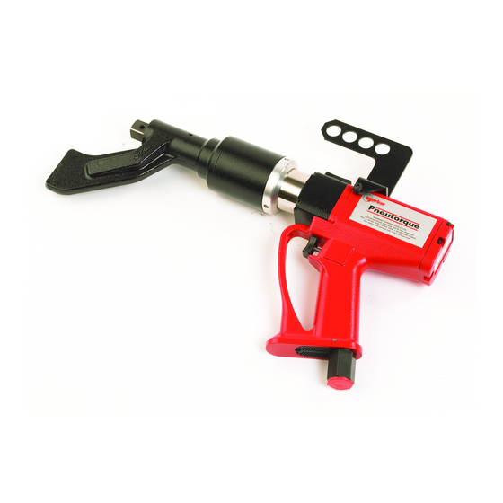
- Page 1 FIXED NOSE EXTENSION PTME-72-1000 STALL TOOLS OPERATORS HANDBOOK (PART NO. 34305) Issue 1 (ENGLISH) NORBAR TORQUE TOOLS LTD, Beaumont Road, Banbury, Oxfordshire, OX16 1XJ, UNITED KINGDOM Tel : + 44 (0) 1295 270333, Fax : + 44 (0) 1295 753643 www.norbar.com...
- Page 3 PAGE 1 OF 13 ISSUE 1 02 2006 CONTENTS PAGE Safety Introduction Features and Functions Set up Instructions Operating Instructions Maintenance Specification Declaration of Conformity Trouble shooting Glossary of terms MODELS COVERED BY HANDBOOK:- ____________________________________________ PART DESCRIPTION MODEL MAXIMUM TOOL TYPE NUMBER TORQUE 1000 N.m...
- Page 4 PAGE 2 OF 13 ISSUE 1 02 2006 SAFETY IMPORTANT: DO NOT OPERATE THE TOOL BEFORE READING THIS HANDBOOK. FAILURE TO DO SO MAY RESULT IN PERSONAL INJURY OR DAMAGE TO THE TOOL. This tool is intended for use with threaded fasteners. Any other use is not recommended. The use of ear protectors is recommended.
-
Page 5: Features And Functions
PAGE 3 OF 13 ISSUE 1 02 2006 INTRODUCTION ® The Pneutorque 52mm series are air driven power tools designed for applying torque to wheel nuts in the range of 200 N.m to 1000 N.m This tool uses the air pressure set on an external pressure regulator to determine the stall torque. -
Page 6: Setup Instructions
PAGE 4 OF 13 ISSUE 1 02 2006 SET UP INSTRUCTIONS WARNING: TO AVOID HAZARD FROM WHIPPING AIR HOSES MAKE ALL CONNECTIONS TO THE TOOL BEFORE TURNING ON THE AIR SUPPLY. Make sure all air hoses are clean and free from dirt. 1. - Page 7 PAGE 5 OF 13 ISSUE 1 02 2006 SETTING CLOCKWISE/COUNTER-CLOCKWISE OPERATION_________________________ Clockwise (Arrow towards drive square) Figure 2a Counter-clockwise (Arrow away from drive square) Figure 2b TIP: To help set the clockwise / counter-clockwise operation run the tool in neutral position before re-engaging.
- Page 8 PAGE 6 OF 13 ISSUE 1 02 2006 SETTING TORQUE FOR RELEASING BOLT ________________________________________ NOTE: THIS PROCEDURE IS ONLY APPLICABLE TO BI-DIRECTIONAL TOOLS. The tools are designed to give a slightly higher torque in counter-clockwise rotation. This may allow some tight bolts to be released without the need to set a higher air pressure.
- Page 9 PAGE 7 OF 13 ISSUE 1 02 2006 OPERATING INSTRUCTIONS WARNING: KEEP HANDS CLEAR OF THE REACTION FOOT. WARNING: WHEN USING THIS TOOL IT MUST BE SUPPORTED AT ALL TIMES IN ORDER TO PREVENT UNEXPECTED RELEASE IN THE EVENT OF FASTENER OR COMPONENT FAILURE.
- Page 10 PAGE 8 OF 13 ISSUE 1 02 2006 B. RELEASING _______________________________________________________________ Fit the Pneutorque® with the correct size impact or high quality socket to suit the fastener to be released. Ensure socket is in good condition. Ensure the clockwise/counter-clockwise selector is correctly set. Rotate the handle into a convenient position relative to the reaction foot.
-
Page 11: Maintenance
Any other maintenance or repairs should be carried out by Norbar or a Norbar approved agent and should form part of a service. Service intervals will depend on the type of usage of the tools and the environment in which they are being used. - Page 12 PAGE 10 OF 13 ISSUE 1 02 2006 DRIVE SHAFT:- ________________________________________________________________ To avoid internal damage (especially due to torque overload), the output drive shaft has been designed to shear first. This saves major internal damage and allows easy shaft removal. Figure 8 To replace drive shaft: Support tool securely in a horizontal position, before commencing this operation...
-
Page 13: Specifications
PAGE 11 OF 13 ISSUE 1 02 2006 SPECIFICATIONS RANGE MAXIMUM TOOL SPEED MODEL OVERLOAD (FREE RUNNING AT MAX. AIR PRESSURE) PTME-72-1000-* 200 N.m 1000 N.m 1100 N.m 125 r/min Repeatability: ± 5% Air Supply: Maximum pressure – 6.3 bar (For maximum torque capacity). Recommended Lubrication: Shell Tellus 15 for the Lubro Control Unit. - Page 14 PAGE 12 OF 13 ISSUE 1 02 2006...
-
Page 15: Troubleshooting
PAGE 13 OF 13 ISSUE 1 02 2006 TROUBLE SHOOTING The following is only a guide, for more complex faults please contact your local Norbar distributor or Norbar directly. PROBLEM LIKELY SOLUTIONS Tool output does not rotate when trigger pulled.
Need help?
Do you have a question about the PNEUTORQUE PTME-72-1000 and is the answer not in the manual?
Questions and answers