Table of Contents
Advertisement
Quick Links
NORBAR TORQUE TOOLS LTD
Beaumont Road, Banbury,
Oxfordshire, OX16 1XJ
UNITED KINGDOM
Tel + 44 (0)1295 270333
Email enquiry@norbar.com
NORBAR TORQUE TOOLS PTY LTD
45–47 Raglan Avenue, Edwardstown,
SA 5039
AUSTRALIA
Tel + 61 (0)8 8292 9777
Email enquiry@norbar.com.au
NORBAR TORQUE TOOLS INC
36400 Biltmore Place, Willoughby,
Ohio, 44094
USA
Tel + 1 866 667 2279
Email inquiry@norbar.us
NORBAR TORQUE TOOLS (NZ) LTD
B3/269A Mt Smart Road
Onehunga, Auckland 1061
NEW ZEALAND
Tel + 64 9579 8653
Email nz@norbar.com.au
© Norbar Torque Tools Ltd 2014
NORBAR TORQUE TOOLS PTE LTD
194 Pandan Loop
#07-20 Pantech Business Hub
SINGAPORE 128383
Tel + 65 6841 1371
Email singapore@norbar.com.au
NORBAR TORQUE TOOLS (SHANGHAI) LTD
E Building–5F, no. 1618 Yishan Road,
Minhang District, Shanghai
CHINA 201103
Tel + 86 21 6145 0368
Email sales@norbar.com.cn
NORBAR TORQUE TOOLS INDIA PVT. LTD
Plot No A-168, Khairne Industrial Area,
Thane Belapur Road, Mahape,
Navi Mumbai – 400 709
INDIA
Tel + 91 22 2778 8480
Email enquiry@norbar.in
www.norbar.com
www.norbar.com/HowtoUseANorTronic
OPERATOR'S MANUAL
®
NORTRONIC
Part Number 34399 | Issue 2 | Original Instructions (English)
Advertisement
Table of Contents

Related Manuals for norbar NORTRONIC 43501


Summary of Contents for norbar NORTRONIC 43501
- Page 1 Tel + 61 (0)8 8292 9777 Tel + 86 21 6145 0368 Email enquiry@norbar.com.au Email sales@norbar.com.cn NORBAR TORQUE TOOLS INC NORBAR TORQUE TOOLS INDIA PVT. LTD 36400 Biltmore Place, Willoughby, Plot No A-168, Khairne Industrial Area, Ohio, 44094 Thane Belapur Road, Mahape, Navi Mumbai –...
-
Page 3: Table Of Contents
Contents Introduction Part Numbers Covered by This Manual Parts Included USB Wireless Adapters (accessory) Software Compatibility Features and Functions Before Use Preparation Battery Fitting / Replacement Ratchet Head Fitting / Replacement Button Functions Measure Display Operation Start Up Peak Reading with Manual Reset Peak Reading with Auto Reset Tool Target Torque Units –... - Page 4 Data Store View Results Erase All About Specifications Maintenance ® NorTronic Calibration Battery Replacement Repair Cleaning Product Disposal Battery Disposal Trouble Shooting Glossary of Terms...
-
Page 5: Introduction
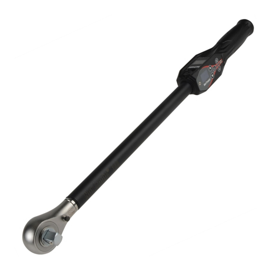
INTRODUCTION ® The NorTronic is an electronic torque and angle wrench capable of measuring, displaying, storing and transmitting test results and receiving configuration settings from TDS (Torque Data System PC software) via the USB or wireless interface. The tool comes in 3 torque capacities: - 50 N·m, 200 N·m & 330 N·m. ®... -
Page 6: Features And Functions
FEATURES AND FUNCTIONS TDS (Torque Data System) software included for complete data management and archiving to a PC. Includes seamless data synchronisation. See TDS Manual part number 34397 for more information. ® All NorTronic tools are Torque Handles with a 16mm spigot to interface to additional end fittings and offsets. -
Page 7: Before Use
BEFORE USE Preparation IMPORTANT: IF THE EQUIPMENT IS USED IN A MANNER NOT SPECIFIED BY THE MANUFACTURER, THE PROTECTION PROVIDED BY THE EQUIPMENT MAY BE IMPAIRED. ® WARNING: ALLOW THE NORTRONIC TO EQUALISE TO THE AMBIENT TEMPERATURE/HUMIDITY BEFORE SWITCHING ON. WIPE OFF ANY MOISTURE BEFORE USE. -
Page 8: Button Functions
BUTTON FUNCTIONS Throughout SETUP and Operation, the buttons perform the following functions: Function Button Operation SETUP Scroll through options or change a selected value. Change Units When changing a value, hold button down for a faster rate change. Zero Torque & Angle display if below the Active From threshold. -
Page 9: Operation
® Upon fitting the batteries and end cap (or pressing any button to wake the NorTronic up from sleep), the Norbar logo is displayed for 2 seconds followed by the measure display: Peak Reading with Manual Reset Operation Torque display... -
Page 10: Peak Reading With Auto Reset
Peak Reading with Auto Reset Torque display Auto Reset Trigger Torque input Active From Zero Torque Hold Time ® When Torque is applied, the NorTronic will track the torque input until it has exceeded the Active From setting (See page 19) and then enters into peak mode for both Torque & Angle. The angle display is shown as “0°”... -
Page 11: Torque Units - Change
® ® To wake the NorTronic , press any button. After the display of the Norbar logo the NorTronic will perform a gyroscope drift calibration. The Gyroscope drift calculation will also be done if the temperature changes by more than 3 degrees. This is necessary to ensure the angle measurement is accurate. -
Page 12: Usb Interface
Do Not Move Calculating █████ This screen is displayed during the Gyroscope drift calculation. ® The NorTronic can now be used. ® NOTE: The Gyro drift calibration will not be done if the NorTronic is woken less than 30 seconds after going to sleep. -
Page 13: Wireless Interface
Wireless Interface ® The NorTronic can be connected to a with installed using an additional USB Wireless Adapter. ® Test Results saved on the NorTronic (to the Data Store) will be copied to TDS when synchronising. The ® Tool Target Tool SETUP configuration can also be sent to the NorTronic Tool from TDS. -
Page 14: Tds Receive Results Interface
TDS Receive Results Interface ® Test Results can be sent as they happen (i.e. in real time) from the NorTronic Tool to via the Receive Results window using the Wireless interfaces. time. Only tool can be interfaced at any If the interface is used, the USB icon will appear on the... -
Page 15: Tool Target - Setting
TOOL TARGET - SETTING Set Target Units NOTE: Set Snug will be shown as Set Target if Angle is Not Enabled. Set Snug Press to change. N·m Set Snug Torque. Press to confirm and go to the button is not functional. -
Page 16: Linked Targets
Linked Targets Linked Targets can only be set up TDS. # of Tests & Next Target can only be specified in the TDS Target. Linked Targets can be sent via the Wireless interface to the Tool. If after the final Target has completed (and No further Target has been specified), the Target becomes... -
Page 17: Tds Target Interface
TDS Target interface ® The NorTronic 1 active Target. Multiple Targets can be set up in and individually downloaded ® NorTronic Target ticked “Set Tool Options” can be changed on the tool unless the “Locked” option has been ® downloaded Update “Set Tool Options”... -
Page 18: Tool Setup
TOOL - SETUP ® All NorTronic Tool - SETUP can be configured in downloaded to the tool. ® NorTronic Tool - SETUP includes: Limits, Units, Time & Date, Sleep, Angle Display, Auto Zero, Active From, Vibrate, Wireless, Auto Reset, Display and Torque Centres. NOTE: Tool - SETUP is active unless the “Lock”... -
Page 19: Torque Limits
LIMITS Press to highlight required setting. UNITS Press to confirm the setting to change. DATE / TIME SLEEP Press to exit to the Options Menu. NOTE: Tool - SETUP is a scrolling screen. Press ANGLE the DOWN button with SLEEP highlighted to go to ANGLE etc. -
Page 20: Units
Units Units ? Press to highlight unit. N·m Kgf·m Press to enable (green) or disable (red). dN·m Kgf·cm SETUP Press to confirm and exit to (saving changes). cN·m gf·m Press the DOWN button with highlighted to go to units screen (shown below). -
Page 21: Sleep
Sleep ® The NorTronic will go to Sleep if there has been No activity for the time set in ‘Sleep After’. During sleep, ® none of the NorTronic functions operate. Sleep After ? Press to change value. Press to confirm and exit to SETUP. ... -
Page 22: Vibrate
Vibrate Vibrate ? Press to change setting. Press to confirm and exit to SETUP. Enabled Vibrate Torque Target Enabled = Tool will when reached. does not vibrate Torque Target Not Enabled = Tool when reached. Wireless Wireless ? Press to change setting. -
Page 23: Auto Reset
Auto Reset (Hold Time ?) Auto Reset ? Press to change setting. If Enabled, pressing will take the user to ‘SETUP Not Enabled Hold Time ?’. If Not enabled the user will return to SETUP. Enabled = Hold the torque (and angle) values the length of the Hold Time setting after the torque has been removed and then reset the display to 0. -
Page 24: Data Store
DATA STORE Data Store Press to change highlighted option. Press to confirm. View Results Press to go to SETUP. Erase All View Results Result Press the buttons to scroll through the Saved 30/03/12 Test Results screen(s). 10:48:10 Press the button on to exit back to Data Store. -
Page 25: About
ABOUT Each of the 3 screens (starting with serial #), is displayed for 2 seconds before returning to SETUP. Tool Identification SERIAL # 2012/123456 MODEL # 4350X Version # Version # 1.XX Hardware options fitted. Options Wireless Angle... -
Page 26: Specifications
SPECIFICATIONS Weight Dimensions (mm) Model Resolution Zero Suppression ® NorTronic 0.01 N·m ± 1 L.S.D (0.01 N·m) 1.20 2.63 ® NorTronic 0.1 N·m ± 1 L.S.D (0.1 N·m) 1.45 3.20 ® NorTronic 0.1 N·m ± 1 L.S.D (0.1 N·m) 1.89 4.17 Display: 2 x 0.95”... -
Page 27: Maintenance
The coin cell should only be replaced by Norbar or a Norbar approved agent. Repair Repair should be carried out at Norbar or by a Norbar approved agent, where all the facilities to ensure the ® NorTronic is functioning at maximum accuracy are available. -
Page 28: Trouble Shooting
Hardware error – return to Norbar. Display shows “Err=4”. Hardware error – return to Norbar. Date & Time not remembered. The coin cell battery has failed. Return to Norbar. ® Cannot zero NorTronic Tool has possibly been overstrained. Return to Norbar.
Need help?
Do you have a question about the NORTRONIC 43501 and is the answer not in the manual?
Questions and answers