Table of Contents
Advertisement
Quick Links
Features
Frequency bands
862 MHz to 928 MHz
431 MHz to 464 MHz
Programmable datarates and modulation
1 kbps to 300 kbps
FSK/GFSK/OOK/MSK/GMSK modulation
Very low power consumption
12.8 mA in PHY_RX mode (maximum front-end gain)
24.1 mA in PHY_TX mode (10 dBm output, single-ended PA)
0.75 µA in PHY_SLEEP mode (32 kHz RC oscillator active)
1.28 µA in PHY_SLEEP mode (32 kHz XTAL oscillator active)
0.33 µA in PHY_SLEEP mode (Deep Sleep Mode 1)
High Sensitivity
Programmable output power
−20 dBm to +13.5 dBm (single-ended PA)
−20 dBm to +10 dBm (differential PA)
Excellent receiver selectivity and blocker resilience
Table 1 Evaluation Boards
Board Number
EVAL-ADF7XXXMBZ3
Eval-ADF7023DB1Z
Eval-ADF7023DB2Z
Eval-ADF7023DB3Z
Eval-ADF7023DB4Z
Arrow.com.
Downloaded from
RF Frequency Description
-
Mother board required for evaluation of the ADF7023 daughter
boards
868/915 MHz
Two separate matching networks: One for the single ended PA and
one for the LNA
868/915 MHz
One combined matching network incorporating the single ended PA
and LNA
433 MHz
Two separate matching networks: One for the single ended PA and
one for the LNA
433 MHz
One combined matching network incorporating the single ended PA
and LNA
R e v 1 . 1
Evaluation Boards for ADF7023
ISM Band Transceiver
EVAL-ADF7023DBxZ
General Description
The ADF7023 is a very low power, high performance, highly
integrated 2FSK/GFSK/OOK/MSK/GMSK transceiver designed
for operation in the 862 MHz to 928 MHz and 431 MHz to
464 MHz frequency bands, which cover the worldwide license-
free ISM bands at 433 MHz, 868 MHz, and 915 MHz. It is
suitable for circuit applications that operate under the
European ETSI EN300-220, the North American FCC (Part
15), the Chinese short-range wireless regulatory standards, or
other similar regional standards.
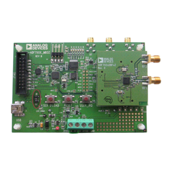
The ADF7023 evaluation platform consists of a 4-layer PCB
daughter card which plugs into the Eval-ADF7xxxMB3Z
motherboard.
| Page 1
Advertisement
Table of Contents

Related Manuals for Analog Devices EVAL-ADF7023DB Z Series


Summary of Contents for Analog Devices EVAL-ADF7023DB Z Series
-
Page 1: Features
Evaluation Boards for ADF7023 ISM Band Transceiver EVAL-ADF7023DBxZ Features General Description Frequency bands 862 MHz to 928 MHz The ADF7023 is a very low power, high performance, highly 431 MHz to 464 MHz integrated 2FSK/GFSK/OOK/MSK/GMSK transceiver designed Programmable datarates and modulation 1 kbps to 300 kbps for operation in the 862 MHz to 928 MHz and 431 MHz to FSK/GFSK/OOK/MSK/GMSK modulation... -
Page 2: Table Of Contents
TABLE OF CONTENTS Features ..............................................1 General Description ........................................... 1 Revision History ..........................................2 Hardware Overview ........................................... 3 Getting Started ............................................ 4 Installing Software ......................................... 4 Mother Board Firmware Version ....................................15 Basic RF testing in SPORT Mode ....................................18 Entering PHY_TX for basic RF Carrier testing ............................... -
Page 3: Hardware Overview
Hardware Overview The Evaluation Platform consists of the Eval-ADF7XXXMB3Z mother board to which an appropriate daughter card may be connected. The available daughter cards are given in Table 1. Schematics for the daughter cards are given in the ADF7023 Evaluation Board Schematics and BOMs section of this document. The mother board may be powered via the USB cable supplied. -
Page 4: Getting Started
Run ADF7023 Rev1.5.4 FULL.exe to install the evaluation software for the ADF7023. The install will place the relevant files in the folder C:\Program Files\Analog Devices BV\ADF7023. It will also create shortcuts on the start menu. Any previous versions of the software will be removed before the installation commences (... - Page 5 Figure 3 Click “Next” ( Figure 3 Figure 4 Click “Next” ( Figure 4 R e v 1 . 1 | Page 5 Arrow.com. Arrow.com. Arrow.com. Arrow.com. Arrow.com. Downloaded from Downloaded from Downloaded from Downloaded from Downloaded from...
- Page 6 Click “I accept this license Agreement” Figure 5 Then Click “Next” ( Figure 5 Click “Next” ( Figure 6 Figure 6 R e v 1 . 1 | Page 6 Arrow.com. Arrow.com. Arrow.com. Arrow.com. Arrow.com. Arrow.com. Downloaded from Downloaded from Downloaded from Downloaded from Downloaded from...
- Page 7 Click “Next” ( Figure 7 Figure 7 Figure 8 Click “Next” ( Figure 8 R e v 1 . 1 | Page 7 Arrow.com. Arrow.com. Arrow.com. Arrow.com. Arrow.com. Arrow.com. Arrow.com. Downloaded from Downloaded from Downloaded from Downloaded from Downloaded from Downloaded from Downloaded from...
- Page 8 Click “Next” ( Figure 9 Figure 9 Figure 10 Click “Next” ( Figure 10 At this point the ADF7xxxMB3Z Motherboard can be plugged into a free USB port. R e v 1 . 1 | Page 8 Arrow.com. Arrow.com. Arrow.com. Arrow.com.
- Page 9 The following screen will appear: Ensure the “Install the software automatically” option is checked as in Figure 11 . Then click “Next” : Figure 11 Click “Continue Anyway” ( Figure 12 Figure 12 R e v 1 . 1 | Page 9 Arrow.com.
- Page 10 Click “Finish” ( Figure 13 Figure 13 R e v 1 . 1 | Page 10 Arrow.com. Arrow.com. Arrow.com. Arrow.com. Arrow.com. Arrow.com. Arrow.com. Arrow.com. Arrow.com. Arrow.com. Downloaded from Downloaded from Downloaded from Downloaded from Downloaded from Downloaded from Downloaded from Downloaded from Downloaded from Downloaded from...
- Page 11 Ensure the evaluation mother board with the desired daughter card is connected to the PC via USB cable before running the software. Run the ADF7023 software from Start-> Programs->Analog Devices->ADF7xxx->ADF7023. Once the software is running press Connect USB ( Figure 16 ).
- Page 12 Using the Evaluation Software Figure 16 Wait until the BUSY signal above the Connect USB button is turned off before pressing any further buttons on the software interface. The Firmware for the motherboard is automatically checked each time the software is loaded to ensure the revisions are kept up to date.
- Page 13 Next enter state PHY_ON by pressing the command CMD_PHY_ON. Figure 18 This can be done by pressing Button A or Button B ( Figure 18 The current status of the ADF7023 will be reflected by the color of the buttons on the ‘‘ ‘‘ ‘‘ ‘‘Commands Commands’’...
- Page 14 Disconnect USB Disconnect USB Note: If at any time it is desired to unplug the USB cable, click ‘‘ Disconnect USB Disconnect USB ’’ first (Figure 19). Figure 19 R e v 1 . 1 | Page 14 Arrow.com. Arrow.com. Arrow.com.
-
Page 15: Mother Board Firmware Version
Mother Board Firmware Version The Motherboard firmware revision check is done automatically when “Connect USB” is clicked. If the firmware revision Figure 20 is not correct a popup screen will appear asking the user to update the Firmware ( Figure 20 To manually check the firmware after connecting the USB select Help ->... - Page 16 Mother Board Firmware Update Before beginning this procedure ensure ONLY the board you wish to update the firmware on is connected to the Figure 22 To update the firmware select “Tools” -> “Motherboard Firmware Download” ( Figure 22 Select the desired firmware version “EVAL_ADF7XXXMB3Z_Rev_2.0.2.5.hex” from the default directory Figure 23 Figure 23 R e v 1 .
- Page 17 Figure 24 Click “Download Firmware” and follow the onscreen instructions ( Figure 24 “SER DLOAD and “RESET” buttons will be referenced and can be found as shown in Figure Figure 25 Disconnect and then reconnect the USB cable from the evaluation platform. The mother board firmware is now updated.
-
Page 18: Basic Rf Testing In Sport Mode
Basic RF testing in SPORT Mode Select the “RF Settings” Tab and set the RF parameters as required. ( Figure 26 point(1)) If not already in PHY_ON enter this state by pressing CMD_PHY_ON. ( Figure 26 point (5)) Select the SPORT Mode ( Figure 26 point (2)) Press Update Needed. - Page 19 • While in PHY_RX with SPORT mode enabled, the received data demodulated by the ADF7023 will appear at the DR SMA connector on the mother board as shown in Figure 27 • A clock synchronized with the demodulated data will appear at the CLK SMA connector as shown in Figure 27 .
-
Page 20: Entering Phy_Tx For Basic Rf Carrier Testing
Entering PHY_TX for basic RF Carrier testing Select the “RF Settings” Tab and set the RF parameters as required. ( Figure 28 point (1) Select “Packet Mode” ( Figure 28 point (2)) Set Tx Test Mode to “Transmit Carrier” ( Figure 28 point (3)) Ensure part is in PHY_ON ( Figure 28 point (4)) -
Page 21: Entering Phy_Tx For Basic Rf Data Testing
Entering PHY_TX for basic RF Data testing Select the “RF Settings” Tab and set the RF parameters as required. ( Figure 29 point (1)) Select the SPORT Mode . ( Figure 29 point (2)) Figure 29 point (4)) Ensure part is in PHY_ON ( Press Update Needed. - Page 22 • While in PHY_Tx with SPORT mode enabled, the transmitted data must synchronized with the output clock seen on the CLK SMA connector on the mother board as shown in ( Figure 30 ) • The Tx data line, from the users Tx device, should be connected to the DT SMA connector as shown in Figure 30 ).
-
Page 23: Simple Rx / Tx Test In Packet Mode
Simple Rx / Tx Test in Packet Mode This section gives a brief introduction on how to Transmit and Receive a packet using the ADF7023 Platform. Rx Setup in Packet Mode The settings which follow are for use with EVAL-ADF7023DB1z daughter boards. If you are using a different Daughter board, ensure that the frequency is set within the correct range of the board you are using. - Page 24 Receiver Board RF Settings Ensure the First ADF7023 Daughter board is correctly plugged into the First Mother board and that the “Current_State” is “PHY_ON” on the First instance of the ADF7023 Software. Refer to Connecting the Evaluation Boards for setup procedures. Select the “RF Settings”...
- Page 25 Receiver Board Rx Packet Settings Using the Tx/Rx packet tab you can set up the packet format and configure the packet handler. ( Figure 32 point (1)) The transmitted preamble length sync word and CRC can be defined by the user. ( Figure 32 point (2)) (Note: Ensure CRC is enabled for this test.
- Page 26 Receiver Board Interrupts Interrupts may be configured for various conditions in the “Interrupts” tab. ( Figure 33 point (1)) Set the “crc_correct” interrupt. ( Figure 33 point (2)) This will give an interrupt signal upon reception of a packet with a valid CRC. Write the settings to the device using the “Update Needed”...
-
Page 27: Tx Setup In Packet Mode
Tx Setup in Packet Mode The settings which follow are for use with EVAL-ADF7023DB1z daughter boards. If you are using a different Daughter board, ensure that the frequency is set within the correct range of the board you are using. Please refer to table x if you are unsure what the frequency range of you board is designed for. Transmitter Board RF Settings econd ADF7023 Daughter board is correctly plugged into the Second Mother board and that the Ensure the S... - Page 28 Transmitter Board Tx Packet Settings Using the Tx/Rx packet tab you can set up the packet format and configure the packet handler. Ensure these settings are the same as the Receiver settings previously set. ( Figure 35 point (1)) The transmitted preamble length sync word and CRC can be defined by the user. ( Figure 35 point (2)) (Note: Ensure CRC is enabled for this test.
- Page 29 Transmitter Board Interrupts Interrupts may be configured for various conditions in the “Interrupts” tab. ( Figure 36 point (1)) Set the “tx_eof” interrupt. ( Figure 36 point (2)) This will give an interrupt signal after a packet has been fully transmitted. Write the settings to the device using the “Update Needed”...
-
Page 30: Reading Interrupt Source On Transmitter Board
Reading Interrupt Source on Transmitter board Once the Transmitter has transmitted a packet you should now see “Interrupt Detected!” on both instances of the software. Figure 37 point (1)) On the Transmitter board the interrupt signifies that a packet has been successfully transmitted. To check the source of the interrupt, click “Read Source”... -
Page 31: Reading Interrupt Source On Receiver Board
Reading Interrupt Source on Receiver board Once the Transmitter has transmitted a packet you should now see “Interrupt Detected!” on the Receiver software instance. Figure 38 point (1)) On the Receiver board the interrupt signifies that a packet has been successfully Received with a valid CRC. -
Page 32: Running A Packet Error Rate Test
Running a Packet Error Rate Test To run a packet error rate test the previous section, Simple Rx / Tx Test in Packet Mode, must first be followed. Once interrupts are observed, on both the Rx and Tx software instances, the Packet Error Rate (PER) test may be used. Configuring the Receiver board for the PER test Once all of the Receiver and packet parameters are setup correctly (as in Rx Setup in Packet Mode section) - Page 33 Configuring the Transmitter board for the PER test Once all of the Transmitter and packet parameters are setup correctly (as in Tx Setup in Packet Mode section) (Figure 40 point (1)) then select the “PER” Tab. (Figure 40 point (2)) Select the “Tx Board Setup”...
-
Page 34: Running A Script
Running a Script 1. Select “Run Script” from the “CMD LIST” drop down menu as shown in Figure 41Figure 41. Figure 41 R e v 1 . 1 | Page 34 Arrow.com. Arrow.com. Arrow.com. Arrow.com. Arrow.com. Arrow.com. Arrow.com. Arrow.com. Arrow.com. Arrow.com. - Page 35 2. Select the path where the script file is stored. (Figure 42Figure 40 point (1)) 3. Click “Execute Script” to run the selected script. (Figure 42Figure 40 point (2) Figure 42 R e v 1 . 1 | Page 35 Arrow.com.
- Page 36 Using Scripts Scripts can be written in Notepad and saved with a file extension of .txt The following are examples can be used: • To write to a PACKET_RAM register enter the line “18xxyy” where “xx” represents the last eight bits of the address to be written to and “yy”...
- Page 37 Scripting Example The following script would be used for the previous examples: //Start of script 1810AB //Set Packet_Ram address 0x010 to AB 1923CD //Set BBRam address 0x123 to CD 1B45EF //Set MCR address 0x345 to EF S120 //Delay for 120ms //Enter PHY_OFF //Enter PHY_ON //Enter PHY_Tx...
-
Page 38: Adf7023 Evaluation Board Schematics And Boms
ADF7023 Evaluation Board Schematics and BOMs Table 2 Components Common to All Daughter Boards Qty Name Value Tolerance PCB Decal Manufacturing Part No. 1.5nF ±5% 0402 GRM155R71H152KA01D C14, C16, C24, C28, 220nF ±10% 0402 GRM155R61A224KE19D C30, C33, C37, C62, C15, C27 100pF ±5% 0402 GRM1555C1H101JZ01D C23, C34, C35 18pF ±5%... - Page 39 47pF ±5% 0402 GRM1555C1H470JZ01D 1.8nH ±5% 0402 Coilcraft 0402CS-1N8XJL 24nH ±5% 0402 Coilcraft 0402CS-24NXJL 12nH ±5% 0402 Coilcraft 0402CS-12NXJL 6.2nH ±5% 0402 Coilcraft 0402CS-6N2XJL 47nH ±5% 0402 Coilcraft 0402CS-47NXJL L5, L10 12nH ±5% 0402 Coilcraft 0402CS-12NXJL Table 4 Eval-ADF7023DB2Z Components (868/915MHz Combined Match) Qty Name Value Tolerance PCB Decal...
- Page 40 C18, C67 270pF ±5% 0402 GRM1555C1H271JA01D 100pF ±5% 0402 GRM1555C1H101JZ01D 15nH ±5% 0402 Coilcraft 0402CS-15NXJL 82nH ±5% 0402 Coilcraft 0402CS-82NXJL L3, L4 27nH ±5% 0402 Coilcraft 0402CS-27NXJL L5, L10 33nH ±5% 0402 Coilcraft 0402CS-11NXJL 100nH ±5% 0402 Coilcraft 0402CS-R10XJL Table 6 Eval-ADF7023DB4Z Components (433MHz Combined Match) Qty Name Value Tolerance PCB Decal...
- Page 41 Figure 43 Separate PA and LNA Matches Board Schematic (DB1Z, DB3Z) R e v 1 . 1 | Page 41 Arrow.com. Arrow.com. Arrow.com. Arrow.com. Arrow.com. Arrow.com. Arrow.com. Arrow.com. Arrow.com. Arrow.com. Arrow.com. Arrow.com. Arrow.com. Arrow.com. Arrow.com. Arrow.com. Arrow.com. Arrow.com. Arrow.com. Arrow.com. Arrow.com.
- Page 42 Figure 44 Combined PA and LNA Match Board Schematic (DB2Z, DB4Z) R e v 1 . 1 | Page 42 Arrow.com. Arrow.com. Arrow.com. Arrow.com. Arrow.com. Arrow.com. Arrow.com. Arrow.com. Arrow.com. Arrow.com. Arrow.com. Arrow.com. Arrow.com. Arrow.com. Arrow.com. Arrow.com. Arrow.com. Arrow.com. Arrow.com. Arrow.com. Arrow.com.
- Page 43 Figure 45 Separate PA and LNA Matches Board Silkscreen (DB1Z, DB3Z) R e v 1 . 1 | Page 43 Arrow.com. Arrow.com. Arrow.com. Arrow.com. Arrow.com. Arrow.com. Arrow.com. Arrow.com. Arrow.com. Arrow.com. Arrow.com. Arrow.com. Arrow.com. Arrow.com. Arrow.com. Arrow.com. Arrow.com. Arrow.com. Arrow.com. Arrow.com. Arrow.com.
- Page 44 Figure 46 Combined PA and LNA Match Board Silkscreen (DB2Z, DB4Z) R e v 1 . 1 | Page 44 Arrow.com. Arrow.com. Arrow.com. Arrow.com. Arrow.com. Arrow.com. Arrow.com. Arrow.com. Arrow.com. Arrow.com. Arrow.com. Arrow.com. Arrow.com. Arrow.com. Arrow.com. Arrow.com. Arrow.com. Arrow.com. Arrow.com. Arrow.com. Arrow.com.
-
Page 45: Eval-Adf7Xxxmb3Z Mother Board Schematics And Silk Screen
Eval-ADF7XXXMB3Z Mother Board Schematics and Silk Screen Figure 47 Mother Board Silkscreen R e v 1 . 1 | Page 45 Arrow.com. Arrow.com. Arrow.com. Arrow.com. Arrow.com. Arrow.com. Arrow.com. Arrow.com. Arrow.com. Arrow.com. Arrow.com. Arrow.com. Arrow.com. Arrow.com. Arrow.com. Arrow.com. Arrow.com. Arrow.com. Arrow.com. Arrow.com. Arrow.com. Arrow.com. Arrow.com. Arrow.com. Arrow.com. Arrow.com. - Page 46 R e v 1 . 1 | Page 46 Arrow.com. Arrow.com. Arrow.com. Arrow.com. Arrow.com. Arrow.com. Arrow.com. Arrow.com. Arrow.com. Arrow.com. Arrow.com. Arrow.com. Arrow.com. Arrow.com. Arrow.com. Arrow.com. Arrow.com. Arrow.com. Arrow.com. Arrow.com. Arrow.com. Arrow.com. Arrow.com. Arrow.com. Arrow.com. Arrow.com. Arrow.com. Arrow.com. Arrow.com. Arrow.com. Arrow.com. Arrow.com.
- Page 47 R e v 1 . 1 | Page 47 Arrow.com. Arrow.com. Arrow.com. Arrow.com. Arrow.com. Arrow.com. Arrow.com. Arrow.com. Arrow.com. Arrow.com. Arrow.com. Arrow.com. Arrow.com. Arrow.com. Arrow.com. Arrow.com. Arrow.com. Arrow.com. Arrow.com. Arrow.com. Arrow.com. Arrow.com. Arrow.com. Arrow.com. Arrow.com. Arrow.com. Arrow.com. Arrow.com. Arrow.com. Arrow.com. Arrow.com. Arrow.com.
- Page 48 R e v 1 . 1 | Page 48 Arrow.com. Arrow.com. Arrow.com. Arrow.com. Arrow.com. Arrow.com. Arrow.com. Arrow.com. Arrow.com. Arrow.com. Arrow.com. Arrow.com. Arrow.com. Arrow.com. Arrow.com. Arrow.com. Arrow.com. Arrow.com. Arrow.com. Arrow.com. Arrow.com. Arrow.com. Arrow.com. Arrow.com. Arrow.com. Arrow.com. Arrow.com. Arrow.com. Arrow.com. Arrow.com. Arrow.com. Arrow.com.
- Page 49 R e v 1 . 1 | Page 49 Arrow.com. Arrow.com. Arrow.com. Arrow.com. Arrow.com. Arrow.com. Arrow.com. Arrow.com. Arrow.com. Arrow.com. Arrow.com. Arrow.com. Arrow.com. Arrow.com. Arrow.com. Arrow.com. Arrow.com. Arrow.com. Arrow.com. Arrow.com. Arrow.com. Arrow.com. Arrow.com. Arrow.com. Arrow.com. Arrow.com. Arrow.com. Arrow.com. Arrow.com. Arrow.com. Arrow.com. Arrow.com.
Need help?
Do you have a question about the EVAL-ADF7023DB Z Series and is the answer not in the manual?
Questions and answers