Table of Contents
Advertisement
Quick Links
One Technology Way • P.O. Box 9106 • Norwood, MA 02062-9106, U.S.A. • Tel: 781.329.4700 • Fax: 781.461.3113 • www.analog.com
Evaluation Board for the
FEATURES
Self-contained board for generating RF frequencies
Flexibility for reference input, PFD frequency, and loop
bandwidth
Accompanying software allows complete control of
synthesizer functions from a PC
Flexibility for changing external inductor to allow different
VCO output frequency ranges
USB-/battery-operated 9 V supplies
PLEASE SEE THE LAST PAGE FOR AN IMPORTANT
WARNING AND LEGAL TERMS AND CONDITIONS.
ADF4360-8
Integrated PLL and VCO Frequency Synthesizer
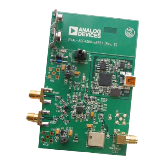
EVALUATION BOARD PHOTOGRAPH
www.BDTIC.com/ADI
Rev. A | Page 1 of 16
Evaluation Board User Guide
GENERAL DESCRIPTION
The
EVAL-ADF4360-8EBZ1
to evaluate the performance of the ADF4360-8 frequency
synthesizer consisting of an integrated PLL and VCO (see Figure 1).
It contains the ADF4360-8BCPZ, a USB connector, and SMA
connectors for the RF outputs. Unpopulated SMA footprints are
available for the power supplies, the chip enable (CE), and the
external reference input. The evaluation board also contains the
loop filter to complete the PLL. It can be modified as necessary for
the user's PLL requirements. A USB cable is included with the
board to allow software programmability.
The package also contains a CD with Windows® software to allow
quick, user-friendly programming of the synthesizer. The CD
contains numerous other PLL data sheets, technical notes, articles,
and ADIsimPLL™ V3.4, Analog Devices, Inc., PLL simulation
software. More information is available at www.analog.com/pll.
Figure 1.
UG-105
board is designed to allow the user
Advertisement
Table of Contents

Subscribe to Our Youtube Channel
Related Manuals for Analog Devices EVAL-ADF4360-8EBZ1


Summary of Contents for Analog Devices EVAL-ADF4360-8EBZ1
-
Page 1: Features
The package also contains a CD with Windows® software to allow quick, user-friendly programming of the synthesizer. The CD contains numerous other PLL data sheets, technical notes, articles, and ADIsimPLL™ V3.4, Analog Devices, Inc., PLL simulation software. More information is available at www.analog.com/pll. EVALUATION BOARD PHOTOGRAPH Figure 1. -
Page 2: Table Of Contents
UG-105 Evaluation Board User Guide TABLE OF CONTENTS Features ....................1 Windows XP OS ................5 General Description ................. 1 Windows Vista OS and Windows 7 (32-Bit) OS ......5 Evaluation Board Photograph ............1 Windows 7 (64-Bit) OS ..............6 ... -
Page 3: Rf Output Stage
Evaluation Board User Guide UG-105 EVALUATION BOARD HARDWARE The evaluation board comes with a cable to connect to the USB RF OUTPUT STAGE port of a PC. The silkscreen for the evaluation board is shown The RF output stage of the board allows the user to insert a in Figure 2. - Page 4 UG-105 Evaluation Board User Guide To find the optimum frequency range for a given inductor, see Figure 4. Ensure that the desired frequency is between the two lines and determine the appropriate inductance needed. INDUCTANCE (nH) Figure 4. Output Center Frequency vs. External Inductor Value www.BDTIC.com/ADI Rev.
-
Page 5: Evaluation Board Software Quick Start Procedures
The install wizard guides you through the installation process. The software is installed in a default directory called C:/Program Files/Analog Devices/ADF4360. The software requires Microsoft’s .NET Framework Version 3.5 or later to be installed on your machine. The installer automati- cally downloads the framework from the Microsoft website if you do not have this installed. -
Page 6: Windows 7 (64-Bit) Os
Browse my computer for driver software. Note that installing this driver package disables older versions Browse to C:\Program Files\Analog Devices\ADF4360. of Analog Devices PLL software; therefore, only install if needed. Click OK or Next. If prompted by Windows security, choose Install this driver software anyway. -
Page 7: Using The Evaluation Board Software
The main interface window opens (see Figure 10). Confirm that Analog Devices RFG.L Eval Board connected is displayed at In the Latches to write section at the bottom of the window, the top of the window. -
Page 8: Changes To Figure 10
UG-105 Evaluation Board User Guide Figure 10. Software Front Panel Display www.BDTIC.com/ADI Rev. A | Page 8 of 16... -
Page 9: Evaluation Board Schematics
Evaluation Board User Guide UG-105 EVALUATION BOARD SCHEMATICS Figure 11. EVAL-ADF4360-8EBZ1 Schematic www.BDTIC.com/ADI Rev. A | Page 9 of 16... -
Page 10: Changes To Figure 12
UG-105 Evaluation Board User Guide Figure 12. EVAL-ADF4360-8EBZ1 Schematic (Continued) www.BDTIC.com/ADI Rev. A | Page 10 of 16... -
Page 11: Changes To Figure 13
Evaluation Board User Guide UG-105 Figure 13. EVAL-ADF4360-8EBZ1 Schematic (Continued) www.BDTIC.com/ADI Rev. A | Page 11 of 16... -
Page 12: Ordering Information
UG-105 Evaluation Board User Guide ORDERING INFORMATION BILL OF MATERIALS Table 1. Reference Designator Part Description Manufacturer/Part No. C1, C3, C5, C29, C30, C32, C37, Capacitor, 0402, 0.1 μF, 16 V Kemet C0402C104K4RAC C38, C39, C40, C41, C42, C43 C2, C4, C6, C8 Capacitor, 0402, 10 pF, 50 V Kemet C0402C100J5GACTU Capacitor, Case A, 22 μF, 6.3 V... -
Page 13: Related Links
Evaluation Board User Guide UG-105 Reference Designator Part Description Manufacturer/Part No. Integrated integer-N synthesizer Analog Devices ADF4360-8BCPZ U2, U3 High accuracy low dropout linear 3 V regulator Analog Devices ADP3300ARTZ-3 ADP3334 adjustable LDO regulator Analog Devices ADP3334ARMZ IC serial EEPROM 8-SOIC... - Page 14 UG-105 Evaluation Board User Guide NOTES www.BDTIC.com/ADI Rev. A | Page 14 of 16...
- Page 15 Evaluation Board User Guide UG-105 NOTES www.BDTIC.com/ADI Rev. A | Page 15 of 16...
-
Page 16: Www.bdtic.com/Adi Rev. A | Page 2 Of
By using the evaluation board discussed herein (together with any tools, components documentation or support materials, the “Evaluation Board”), you are agreeing to be bound by the terms and conditions set forth below (“Agreement”) unless you have purchased the Evaluation Board, in which case the Analog Devices Standard Terms and Conditions of Sale shall govern. Do not use the Evaluation Board until you have read and agreed to the Agreement.
Need help?
Do you have a question about the EVAL-ADF4360-8EBZ1 and is the answer not in the manual?
Questions and answers