Table of Contents
Advertisement
Quick Links
One Technology Way • P.O. Box 9106 • Norwood, MA 02062-9106, U.S.A. • Tel: 781.329.4700 • Fax: 781.461.3113 • www.analog.com
Evaluation Board for the
FEATURES
General-purpose evaluation board for
including octave range VCO, loop filter and TCXO
Contains the
ADF4150HV
frequency synthesizer (500 MHz to
3 GHz)
Contains the
ADF5001
prescaler to allow optional
connection of external microwave VCOs without need for
an active loop filter
Accompanying software allows complete control of
synthesizer functions from a PC
EVALUATION KIT CONTENTS
EVAL-ADF4150HVEB1Z
board
CD that includes
Self-installing software that allows users to control the
board and exercise all functions of the device
Electronic version of the
Electronic version of the UG-406 user guide
ADDITIONAL EQUIPMENT
PC running Windows XP or more recent version
Power supply
Spectrum analyzer
Oscilloscope (optional)
PLEASE SEE THE LAST PAGE FOR AN IMPORTANT
WARNING AND LEGAL TERMS AND CONDITIONS.
ADF4150HV,
ADF4150HV
data sheet
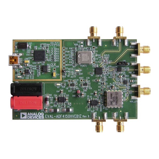
EVALUATION BOARD
Figure 1.
Evaluation Board User Guide
ADF4150HV
PLL Frequency Synthesizer
DOCUMENTS NEEDED
ADF4150HV
REQUIRED SOFTWARE
Analog Devices
ADIsimPLL
GENERAL DESCRIPTION
This board is designed to allow the user to evaluate the
performance of the ADF4150HV frequency synthesizer for
phase-locked loops (PLLs). Figure 1 shows the board, which
contains the
control oscillator (VCO) of 1 GHz to 2 GHz octave range and
up to 28 V high tuning voltage, reference oscillator (TCXO)
of 25 MHz frequency for the reference input, power supply
connectors, and an RF output. The ADF5001 prescaler allows
for optional direct connection of external microwave VCOs
without the need for an active loop filter.
The evaluation kit also contains software that is compatible with
Windows® XP and later versions to allow easy programming of
the synthesizer.
A USB port in the PC is required to program the part.
EVAL-ADF4150HVEB1Z
Rev. 0 | Page 1 of 24
data sheet
ADF4150HV
software (Version 2 or higher)
ADF4150HV
synthesizer, loop filter, voltage
UG-406
Advertisement
Table of Contents

Subscribe to Our Youtube Channel
Related Manuals for Analog Devices EVAL-ADF4150HVEB1Z


Summary of Contents for Analog Devices EVAL-ADF4150HVEB1Z
-
Page 1: Features
ADF4150HV, ADF4150HV data sheet including octave range VCO, loop filter and TCXO REQUIRED SOFTWARE Contains the ADF4150HV frequency synthesizer (500 MHz to Analog Devices ADF4150HV software (Version 2 or higher) 3 GHz) ADIsimPLL Contains the ADF5001 prescaler to allow optional... -
Page 2: Table Of Contents
UG-406 Evaluation Board User Guide TABLE OF CONTENTS Features ....................1 Output Signals ................4 Evaluation Kit Contents ..............1 Default Operation Settings ............4 Additional Equipment ..............1 Additional Options ...............5 Documents Needed ................1 Phase Noise Measurement ............5 Required Software ................ 1 Evaluation Board Setup Procedure ..........6 General Description ................. -
Page 3: Quick Start Guide
Connect the spectrum analyzer to the SMA connector, Install the ADF4150HV software. VCO_I/O. Connect the EVAL-ADF4150HVEB1Z board to the PC. Measure the results. Follow the hardware driver installation procedure. Connect the power supplies as follows: 30 V to banana connectors 5 V to the test point labeled +5V on the board Rev. -
Page 4: Evaluation Board Hardware
UG-406 Evaluation Board User Guide EVALUATION BOARD HARDWARE EVAL-ADF4150HVEB1Z schematics are shown in Figure 25, from the VCO ouput, the ADL5541 is not needed and can be Figure 26, Figure 27, and Figure 28. The silkscreen of the bypassed. evaluation board is shown in Figure 2. -
Page 5: Additional Options
Evaluation Board User Guide UG-406 Prescaler for Microwave VCO The board contains the ADF5001, an 18 GHz divide-by-4 prescaler for users who want to interface a high frequency microwave VCO to the ADF4150HV. For example, using a 12 GHz external VCO, use the VTUNE SMA as described in the External VCO Option section, but, in this case, connect the VCO output to the PRE_IN SMA connector. -
Page 6: Evaluation Board Setup Procedure
UG-406 Evaluation Board User Guide EVALUATION BOARD SETUP PROCEDURE SOFTWARE INSTALLATION Use the following steps to install the software. Install the Analog Devices ADF4150HV software by double-clicking ADF4150HV Setup.msi. If you are using Windows XP, follow the instructions in the Windows XP Software Installation Guide section (see Figure 5 to Figure 9). - Page 7 Evaluation Board User Guide UG-406 Figure 12. Windows Vista/7 ADF4150HV Software Installation, Confirm Figure 9. Windows XP ADF4150HV Software Installation, Installation Installation Complete Click Next. Click Close. Windows Vista and Windows 7 Software Installation Guide Figure 13. Windows Vista/7 ADF4150HV Software Installation, Start Installation Click Install.
- Page 8 Figure 18. Windows XP USB Driver Installation, Complete Installation Figure 16. Windows XP USB Driver Installation, Install Options Click Finish. Click Next. Note that Figure 16 may list Analog Devices RFG.L Eval Board instead of ADF4xxx USB Adapter Board. Rev. 0 | Page 8 of 24...
-
Page 9: Evaluation Board Software
UG-406 EVALUATION BOARD SOFTWARE The control software for the EVAL-ADF4150HVEB1Z Note that, when connecting the board, it takes about 5 sec to available on the CD included in the evaluation kit. To install the 10 sec for the status label to change. - Page 10 UG-406 Evaluation Board User Guide Use the Frequency text box in the Reference section to set the indicating that it must be clicked to program the part with the correct reference frequency. The default reference on the new value. Clicking the Update ALL button programs all software window is at 25 MHz and matches the frequency of the register values simultaneously.
- Page 11 Evaluation Board User Guide UG-406 Figure 20. Register Settings Windows for Register 1, Register 2, Register 3, Register 4, and Register 5 Figure 21. Frac_Mod_Form Window Allows Direct Control of Integer, Modulus, Fractional, and Output Divider Values Rev. 0 | Page 11 of 24...
- Page 12 UG-406 Evaluation Board User Guide Figure 22. Registers Window Shows Current Values of All Registers of the Part Rev. 0 | Page 12 of 24...
-
Page 13: Evaluation And Test
Evaluation Board User Guide UG-406 EVALUATION AND TEST To evaluate and test the performance of the ADF4150HV, use the following procedure: If using a different VCO and loop filter than provided on the board, ensure that a VCO and loop filter are properly inserted on the board. -
Page 14: Evaluation Board Schematics And Artwork
UG-406 Evaluation Board User Guide EVALUATION BOARD SCHEMATICS AND ARTWORK Figure 25. Evaluation Board Schematic (Page 1) Rev. 0 | Page 14 of 24... - Page 15 Evaluation Board User Guide UG-406 Figure 26. Evaluation Board Schematic (Page 2) Rev. 0 | Page 15 of 24...
- Page 16 UG-406 Evaluation Board User Guide Figure 27. Evaluation Board Schematic (Page 3) Rev. 0 | Page 16 of 24...
- Page 17 Evaluation Board User Guide UG-406 Figure 28. Evaluation Board Schematic (Page 4) Rev. 0 | Page 17 of 24...
- Page 18 UG-406 Evaluation Board User Guide Figure 29. Layer 1 (Component Side) Rev. 0 | Page 18 of 24...
- Page 19 Evaluation Board User Guide UG-406 Figure 30. Layer 2 (Ground Plane) Rev. 0 | Page 19 of 24...
- Page 20 UG-406 Evaluation Board User Guide Figure 31. Layer 3 (Power Plane) Rev. 0 | Page 20 of 24...
- Page 21 Evaluation Board User Guide UG-406 Figure 32. Layer 4 (Solder Side) Rev. 0 | Page 21 of 24...
-
Page 22: Bill Of Materials
UG-406 Evaluation Board User Guide BILL OF MATERIALS Table 1. Reference Designator Value Description Manufacturer/Part Number Red test point Vero 20-313137 3V3_USB, 5V_USB Do not insert Red test point AGND Black test point Vero 20-2137 2.2 nF 50 V X7R SMD ceramic capacitor Multicomp MCCA000229 47 nF 50 V X7R SMD ceramic capacitor... -
Page 23: Related Links
Wuerth Elektronik 7427-92642 REFIN, RFOUT+, RFOUT− End-launch 50 Ω SMA jack Emerson Network 142-0701-851 T1, T2 Do not insert Red test point Analog Devices ADF4150HVBCPZ U2, U3 Positive voltage regulator; On Semiconductor LM317LDG adjustable U4, U5 3.3 V linear regulator Analog Devices ADP150AUJZ-3.3... - Page 24 By using the evaluation board discussed herein (together with any tools, components documentation or support materials, the “Evaluation Board”), you are agreeing to be bound by the terms and conditions set forth below (“Agreement”) unless you have purchased the Evaluation Board, in which case the Analog Devices Standard Terms and Conditions of Sale shall govern. Do not use the Evaluation Board until you have read and agreed to the Agreement.
Need help?
Do you have a question about the EVAL-ADF4150HVEB1Z and is the answer not in the manual?
Questions and answers