
Related Manuals for Xtool H6 Pro


Summary of Contents for Xtool H6 Pro
- Page 1 USER MANUAL H6 Pro Smart Diagnostics System Shenzhen Xtooltech Intelligent Co., LTD...
-
Page 3: Copyright
(electronic, mechanical, photocopying, recording, or other forms). ECLARATION This manual is designed for the usage of the H6 PRO Smart Diagnostics System and provides operating instructions and product descriptions for users of the H6 PRO Smart Diagnostics System. -
Page 4: Operation Instructions
Use the device only as described in this manual. Xtool is not responsible for any consequences of violating the laws and regulations caused by using the product or its data information Xtool shall not be liable for any incidental or consequential damages or for any... -
Page 5: Aftersales-Services
Please keep it away from water, moisture, high temperature, or very low ⚫ temperature. If necessary, calibrate the screen before testing to ensure the accuracy of LCD ⚫ performance. Keep the main unit away from strong magnetic fields. ⚫ Please keep your device always connected to the Internet. When the device is off ⚫... -
Page 6: Table Of Contents
Content TRADEMARKS ........................I COPYRIGHT ..........................I DECLARATION ........................I OPERATION INSTRUCTIONS ................... II CAUTIONS! ..........................II AFTERSALES-SERVICES....................III 1 GENERAL INTRODUCTION ..................1 1.1. Tablet Overview ....................1 Front View of Tablet ............................2 Back View of Tablet ............................2 Host Ports................................3 1.2. - Page 7 Function Buttons ............................... 12 Navigation Buttons ............................13 Notification Bar ..............................14 2.3. Factory Reset ....................14 3 UPDATE & DELETE ..................... 19 3.1. Update software ....................19 3.2. Delete Software ....................19 4 DIAGNOSIS ........................21 4.1. Vehicle Connection ................... 21 4.2.
- Page 8 6 REPORT .......................... 63 6.1. Report ........................63 6.2. Replay ........................66 6.3. File Manager ...................... 67 7 SETTINGS ........................69 7.1. Language ......................69 7.2. Units ........................71 7.3. Bluetooth ......................71 7.4. My Workshop Info ................... 72 7.5. VCI Information ....................
- Page 9 Q9: Failed to activate or register ................79 Q10: Failed to turn on when charging ..............79 Q11: Failed to open the diagnosis app ..............79 Q12: Failed to enter Vehicle menu ................. 80 WARRANTY & SERVICES ..................81 SHENZHEN XTOOLTECH INTELLIGENT CO., LTD..........82...
-
Page 10: General Introduction
Please confirm the OBD connector specifications configured on your car before connecting. 1.1. TABLET OVERVIEW The main unit of the H6 PRO Smart Diagnostics System is the tablet. It allows you to operate all diagnosis functions, and it can also work as a normal Android tablet. -
Page 11: Front View Of Tablet
FRONT VIEW OF TABLET Figure 1-1 Sample of Tablet Front View The front of the tablet is mainly a touchable display screen, you can use your fingers to operate on the screen to finish most of the diagnosis process. BACK VIEW OF TABLET ①... -
Page 12: Host Ports
① Camera: Used for taking pictures. ② Nameplate: Show the basic information about the tablet such as product name and serial number, etc. ③ Loudspeaker: It supports external sound playback. HOST PORTS ④ ① ⑤ ② ③ ⑥ Figure 1-3 Sample of Tablet Host Ports ①... -
Page 13: Vci Box
1.2. VCI BOX To communicate with the vehicle via OBD, H6 PRO also comes up with a wireless diagnostics module, also known as the VCI box. The tablet needs a Bluetooth connection with the VCI box to get access to all software. -
Page 14: Top/Bottom View
TOP/BOTTOM VIEW ① ② Bottom Figure 1-5 Sample of VCI Box, screen 2 ① DB15 Port: Used to connect the VCI box to the OBDII port on the vehicle. ② USB-B Port: Used to connect the VCI box to the tablet using USB-B to USB3.0 cable 1.3. -
Page 15: Packing Kit
Input Voltage 12V DC Operating Temperature -10~50℃ Relative Humidity < 90% Dimensions 315.07×218.35×34.61 mm 1.4. PACKING KIT Table 1-2 Packing List Category Name OBD II-16 HONDA-3 BMW-20 TOYOTA-17 MAZDA-17R KIA-20 HYUNDAI/KIA-10 NISSAN-14 GM/DAEWOO-12 SELFTEST UNIVERSAL-3 Test Connectors SUZUKI-3 FIAT-3 CITROEN-2 AUDI-4 MITSUBISHI-12+16 Rear Test Line DB15... -
Page 16: Getting Started
ETTING TARTED 2.1. ACTIVATION After first-time users press and hold the power button to turn on the system, the system will automatically enter the guide process and request to select the language for the operating system. Figure 2-1 Sample of Selection Languages After setting the system language, you will enter the activation page, as shown in the figure below. - Page 17 Figure 2-2 Sample of Activation (Screen 1) Click Start Activate to enter the activation page, as shown below: Figure 2-3 Sample of Activation (Screen 2) A pop-up window showing Activation Success indicates that you have completed the first boot setup, click OK to enter the diagnostic system and start using the device.
-
Page 18: Main Interface
Figure 2-4 Sample of Activation (Screen 3) 2.2. MAIN INTERFACE OPERATION SYSTEM The picture below (Fig 2-5) is the home screen of the operating system of the device. You can also return to this interface at any time by clicking the home button on the bottom navigation bar. - Page 19 H6 Pro Smart Diagnostics System: This app provides full system diagnostic functions and also offers a range of specialist maintenance services. It will be referred to as the “H6 Pro Smart Diagnostics System App” later in this manual.
-
Page 20: Main Menu
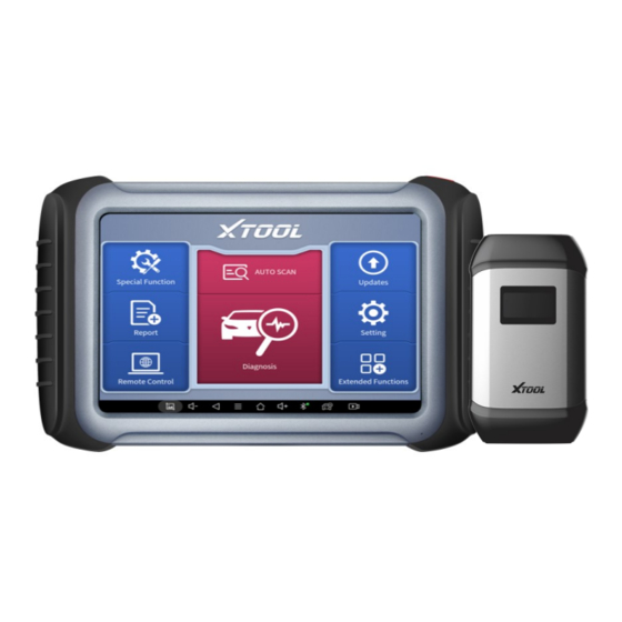
Figure 2-6 Sample of ES File Explorer MAIN MENU Every time start the tablet, you will automatically enter the H6 PRO Smart Diagnostics System app with the following main screen. Tap on the diagnosis application button on the menu, the main menu will be shown as below:... -
Page 21: Function Buttons
Figure 2-7 Sample of APP Main Page This main menu contains Function Buttons and Navigation Buttons. The touch screen navigation is made up of several menus, and you can quickly access functions by clicking on the icons. A detailed description of the menu structure can be found in the Function Buttons next section FUNCTION BUTTONS... -
Page 22: Navigation Buttons
Enter TeamViewer for remote support Update the software through the Internet Select the language and unit shown in the app, and check the Bluetooth status, device info, and workshop info View more functions like the endoscope Check the diagnosis report that is recorded on your device, print it as PDF files, or share it with other devices NAVIGATION BUTTONS Instructions for operating the navigation bar buttons at the bottom of the screen, as... -
Page 23: Notification Bar
NOTIFICATION BAR Slide down to open the notification bar. You can adjust the brightness of the screen when you need it, and you can also connect Wi-Fi and so on. Figure 2-8 Sample of NOTIFICATION BAR 2.3. FACTORY RESET After using the device for the first time or resetting the factory settings to the device, the system will automatically enter the Activation Guide program. - Page 24 Figure 2-9 Sample of How to Select Languages After selecting the system language, click Next to enter the Wi-Fi connection page, as shown below: Figure 2-10 Sample of Selecting Wi-Fi Select a network to connect to on the Wi-Fi connection page. After a successful network connection, the automatic system will jump to Factory mode to download the software:...
- Page 25 Figure 2-11 Sample of Factory Mode Once the software has been downloaded, the tablet will automatically reboot and request the system language selection again. Figure 2-12 Sample of Selecting Languages After setting the system language, you will enter the activation page, as shown in the figure below.
- Page 26 Figure 2-13 Sample of Activation, Screen 1 Click Start Activate to enter the activation page, as shown below: Figure 2-14 Sample of Activation, Screen 2 A pop-up window showing Activation Success indicates that you have completed the first boot setup, click OK to enter the diagnostic system and start using the device.
- Page 27 Figure 2-15 Sample of Activation, Screen 3 If you meet problems like “Registration failed”, please check your network or contact Xtool aftersales services: supporting@xtooltech.com...
-
Page 28: Update & Delete
UPGRADE, and it will show as below: Figure 3-1 Sample of How to Update Vehicle Software H6 PRO Smart Diagnostics System has a three-year free subscription when activated. When you click “update” and it shows “your device is now out of subscription”, please contact your dealer. - Page 29 Figure 3-2 Sample of How to Delete Vehicle Software ** When the device prompts that the memory is insufficient, you can delete the models that are not frequently used to release the memory.
-
Page 30: Diagnosis
4.1. VEHICLE CONNECTION To start the diagnosis process, the VCI communication box should establish communication with the vehicle. For H6 Pro, it is compatible with both Bluetooth communication and wired communication to connect the tablet and VCI box. ⚫ Bluetooth Connection Figure 4-1 Sample of How to Connect Device to Vehicle via Bluetooth ①... - Page 31 Figure 4-2 Sample of How to Connect Device to Vehicle via Wire ①Data Cable for USB 3.0 to Type B; ②V204 BOX; ③ Main Test Cable; ④ OBD2-16 Adapter ⚫ Please follow the steps below. 1. Turn on the tablet. 2.
-
Page 32: Vehicle Selection
4.2. VEHICLE SELECTION Click the “Diagnosis” icon on the main screen and get into the diagnosis menu. All brands will be shown on the screen. Please select the region of your vehicle, click the correct brand, and start the diagnosis process. - Page 33 compatible with some protocols from earlier model years. In addition, some cars cannot read their VIN if it is not written in the engine. Fig 4-3 Sample of AUTO SCAN ⚫ MANUAL ENTER It supports manual input of car VIN code. When entering the VIN code manually, make sure that the 17 characters entered are correct to avoid reading failure.
- Page 34 Fig 4-4 Sample of Manually Inputting Vin ⚫ SELECT VEHICLE BY AREA In addition to the above 3 methods, you can also choose a car brand according to the region. You can select the vehicle model that needs to be diagnosed according to the area, as shown below: Figure 4-5 Sample of Vehicle Selection by Ares ⚫...
- Page 35 Figure 4-6 Sample of OBD2 functions The vehicles equipped with a standard OBD2-16 interface can read the vehicle information through this function. OBD2 functions include reading and clearing, reading live data, reading freeze-frame, reading ECU information, component test, on-board monitor test, O2S monitoring test, I/M readiness, and part functions that are not supported for some specific models.
-
Page 36: Diagnosis Functions
DEMO is a demonstration program. You can perform basic diagnosis functions without connecting to the car. 4.3. DIAGNOSTICS FUNCTIONS Diagnostics functions supported by H6 Pro Smart Diagnostics System are as below: Read ECU Information ⚫ Read/Clear Trouble Code ⚫... - Page 37 Figure 4-7 Sample of Basic Function ◼ Read ECU Information This function is to read ECU version information, which is the equivalent of "System Identification" or "System information” in some electronic control systems, which means to read ECU-related software and hardware versions, models, and production date of diesel engine, part number, etc.
- Page 38 ◼ Read Trouble Code Read trouble codes that are stored in ECU. For the fault code, the diagnostic instrument will give specific detailed definitions and explanations to help you locate and eliminate the car fault. Figure 4-9 Sample of Reading DTC ...
- Page 39 Figure 4-10 Sample of Clear DTC The trouble codes can’t be erased without eliminating all the troubles, which will cause the diagnostic tool to always read the trouble code because the code will always be saved in ECU. ◼ Read Live Data That is to read the parameters of the running engine, such as oil pressure, temperature, engine speed, fuel oil temperature, coolant temperature, intake air temperature, etc.
- Page 40 Figure 4-11 Sample of PIDs List ⚫ Click the magnifying glass on the top right, you can search for related PIDs based on keywords Figure 4-12 Sample of the PIDs List related by Key Words...
- Page 41 ⚫ Custom Support to show the selected PIDs. Figure 4-13 Sample of Custom the PIDs Click Display All, back to the page which displays all PIDs ⚫ Data recording Supports recording the current data value in the form of text, you can view the Reports->Data Replay.
- Page 42 Figure 4-14 Sample of the PIDs Combination ◼ Actuation Test The actuation test, also known as bidirectional control, is a generic term used to describe sending and receiving information between one device and another. The vehicle engineers responsible for designing computer control systems programmed them so a scan tool could request information or command a module to perform specific tests and functions.
- Page 43 Figure 4-16 Sample of the Actuation Test Menu This function allows the device to send information to and receive information from, vehicle control modules. For example, in the case of OBD II generic information Mode 1 (which relates to data parameters), the scan tool user initiates a request for information from the powertrain control module (PCM), and the PCM responds by sending the information back to the scan tool for display.
- Page 44 Take Renault Duster ii ph as an example, after selecting the system to enter the lower freeze frame menu, the device will list all the fault codes under the system. Users can click on a fault code, such as DF1068 to view the freeze frame recorded by the car when the fault code occurs, including context when the fault appeared, and current context and additional data.
- Page 45 Figure 4-19 Sample of the Freeze frame for Renault Duster ii ph (Screen 3) Additional data: record other data related to the fault Figure 4-20 Sample of the Freeze frame for Renault Duster ii ph (Screen 4) ◼ Special functions...
-
Page 46: Ecu Coding & Programming
Figure 4-21 Sample of the Special Functions for the Injection system of Renault Duster ii ph Usually, special functions provide various reset or re-learning function menus for most vehicle systems. You can easily and quickly solve some faults through special functions for your car. - Page 47 ⚫ ECU Coding ECU Coding, also known as Teach-in Program, or Component Adaptation, is used to reprogram adaptive data for electronic control modules after repairs or replacements of parts. ※NOTE: Codable control modules/components are system-specific, which means that not all control modules are codable. ⚫...
- Page 48 IMPORTANT When reprogramming onboard, please always make sure the vehicle battery is fully charged and in good working condition to avoid the operation failure caused by the abnormal voltage below the proper operating voltage. Sometimes the failure can be recovered, but the failed reprogramming can also cause a fault in the control module. We recommend connecting an external battery maintainer to the vehicle to ensure a steady voltage is maintained throughout programming.
-
Page 49: Special Functions
Due to the limitation of screenshots, the special functions shown in this picture are not complete. All special functions supported by the H6 PRO Smart Diagnostics System are subject to the actual special functions displayed on the device. -
Page 50: Oil Reset
5.1. OIL RESET Reset the Engine Oil Life System, which calculates the optimum oil life change interval based on the vehicle’s driving conditions and climate. The oil life reminder must be reset each time the oil is changed so that the system can calculate when the next oil change is required. -
Page 51: Epb
Figure 5-2 Sample of oil reset function (screen 1) Enter the Maintenance mileage reset menu. Input reasonable value of mileage and press OK. Figure 5-3 Sample of oil reset function (screen 2) Message of ‘Reset success’ displayed when Oil Reset function has successfully performed. - Page 52 1. If the brake pad wears the brake pad sense line, the brake pad sense line will send a signal to the onboard tablet asking for replacing the brake pad. After replacing the brake pad, you must reset the brake pad. Otherwise, the car alarms.
-
Page 53: Sas
Enter the Enter maintenance mode menu and release the handbrake brake. And press OK after completing the instructions shown. Figure 5-5 Sample of EPB function (screen 2) Wait until the message ‘Successful operation’ pops up. And press OK to exit the menu. Enter the Exit maintenance mode menu and wait until the message of ‘‘Successful operation’... - Page 54 To reset the steering angle, you need to first find the relative zero point position for the car to drive in a straight line. Taking this position as a reference, the ECU can calculate the accurate angle for left and right steering. After replacing the steering angle position sensor, replacing steering mechanical parts (such as steering gearbox, steering column, end tie rod, steering knuckle), performing four-wheel alignment, or recovering the car...
- Page 55 Figure 5-7 Sample of SAS function (screen 2) Follow the instructions displayed and press OK after completing the instructions shown. Figure 5-8 Sample of SAS function (screen 3) Wait until the following instruction is displayed and press OK after completing the instructions shown.
-
Page 56: Dpf
Figure 5-9 Sample of SAS function (screen 4) Message of ‘Function execution is completed’ displayed when SAS function has successfully performed. 5.4. The Diesel Particle Filter (DPF) function manages DPF regeneration, DPF component replacement teach-in, and DPF teach-in after replacing the engine control module (ECM). - Page 57 indicators displaying. A service regeneration can be requested in the workshop using the diagnostic tool. DPF regeneration is used to clear PM (Particulate Matter) from the DPF filter through continuous combustion oxidation mode (such as high-temperature heating combustion, fuel additive, or catalyst to reduce PM ignition combustion) to stabilize the filter performance.
- Page 58 Figure 5-10 Sample of DPF function (screen 1) Read the fuel tank level and make sure that it fulfills the requirement displayed. Read the carbon deposit load. Choose the drive to warm up and follow the instructions listed below. And press OK after completing the instructions shown. Figure 5-11 Sample of DPF function (screen 2)
- Page 59 Read the note carefully and follow the instructions shown on the screen. And press OK after completing the instructions shown. Figure 5-12 Sample of DPF function (screen 3) Follow the instructions displayed and press OK after completing the instructions shown. Please pay attention to the Note. Figure 5-13 Sample of DPF function (screen 4)
- Page 60 Press the OK button to start the regeneration. Figure 5-14 Sample of DPF function (screen 5) 10. Wait for the value of the carbon deposit to decrease until a message of ‘Emergency regeneration has been completed’ popes up, this process may take up to 40 minutes. Figure 5-15 Sample of DPF function (screen 5)
-
Page 61: Bms Reset
11. Wait for 2 minutes to let the particulate filter cool down. Figure 5-16 Sample of DPF function (screen 6) 12. Press drop out to exit the DPF function. 5.5. BMS RESET The Battery Management System (BMS) allows the scan tool to evaluate the battery charge state, monitor the close-circuit current, register the battery replacement, and activate the rest state of the vehicle. - Page 62 functions, such as automatic start & stop function, sunroof without one- key trigger function, and power window without automatic function. Battery matching is performed to re-match the control module and ⚫ motoring sensor to detect battery power usage more accurately, which can avoid an error message displayed on the instrument cluster.
-
Page 63: Throttle
Figure 5-18 Sample of BMS function (screen 2) Enter the 10-digit battery serial number and press OK after the input. Figure 5-19 Sample of BMS function (screen 3) 5.6. THROTTLE Throttle Position Sensor (TPS) Match, this function enables you to make initial settings to throttle actuators and returns the “learned”... - Page 64 ECU to the default state. Doing so can accurately control the actions of regulating throttle (or idle engine) to adjust the amount of air intake. The operation guidelines of the Throttle function are shown below: Enter the Throttle menu and choose relevant models according to the vehicle being tested.
-
Page 65: Injector Coding
Figure 5-21 Sample of throttle function (screen 2) Press the F2 button and wait until a message of ‘Match successfully’ pops up. 5.7. INJECTOR CODING This function can write the identification code of the fuel injector into the ECU so that the ECU can recognize and work normally. Write actual injector code or rewrite code in the ECU to the injector code of the corresponding cylinder for controlling accurately and correcting cylinder injection quantity. - Page 66 The identification of the fuel injector includes its working accuracy value and type value. When replacing it, you need to find the corresponding model for replacement. At present, mainstream cars support injector coding functions. The operation guidelines of the Injector Coding function are shown below: Enter the Injector coding menu and choose relevant chassis models according to the vehicle being tested.
- Page 67 Figure 5-23 Sample of injector coding function (screen 2) Enter the Change the value of cylinder menu of the replaced injector(s), enter the new 5-digit value, and then press OK. Figure 5-24 Sample of injector coding function (screen 3) Wait until the message ‘Write successfully’ pops up. Turn off the ignition switch.
-
Page 68: Gearbox Match
Wait until the message asked you to turn on the ignition switch. Re-enter the Fuel injection nozzle injection volume adjustment menu to check whether the new value(s) are shown. Figure 5-25 Sample of injector coding function (screen 4) 5.8. GEARBOX MATCH After changing the gearbox or changing the gearbox ECU, you need to use the gearbox matching function to re-match the engine and the gearbox. -
Page 69: Gear Learning
Read the note and press OK to continue the Gearbox Matching function. Figure 5-26 Sample of gearbox matching function (screen 1) Wait until the message ‘Successful operation’ pops up. 5.9. GEAR LEARNING The crankshaft position sensor learns crankshaft tooth machining tolerance and saves to the tablet to more accurately diagnose engine misfires. - Page 70 The operation guidelines of the Gear learning function are shown below: Enter the Gear learning menu and choose relevant models according to the vehicle being tested. Turn on the ignition switch to start the vehicle. Enter the Tooth Learning menu. Read carefully and complete the requisites listed before performing the gear learning function.
- Page 71 Figure 5-28 Sample of gear learning function (screen 2) Press the accelerator pedal down and hold it until a message of ‘The learning is successful, please release the accelerator pedal.’ pops up. Release the accelerator pedal and press OK to exit the gear learning function.
-
Page 72: Report
EPORT A diagnostic Report is used for viewing and printing the saved files, such as Live Data, Trouble Codes, or pictures generated in the process of diagnosis, users also can view a record of which cars have been previously tested. It includes 3 parts: Report ⚫... - Page 73 Figure 6-2 Sample of Report List When you open the report, located in the header of the table is the studio information you filled in advance in the system setup, then the information of the vehicle, including the diagnosis date and time, VIN, vehicle brand, diagnosis path, etc., as shown as below: Figure 6-3 Sample of Report ◼...
- Page 74 As you can see, you also could click " Print PDF Report " at the bottom right corner to output the pdf report. If you need to close the report, you could tap on the button “Exit”. Please follow the below steps to print your report▼ Step 1: Install an APP that can drive your target printer.
-
Page 75: Replay
Figure 6-5 Sample of Report, Screen 2 6.2. REPLAY This function allows you to replay the living data recorded during the diagnosis process. Figure 6-6 Sample of Data Playback, Screen 1 Before replaying the living data, please make sure you click on the "Save to Reference" button during the diagnosis... -
Page 76: File Manager
Figure 6-7 Sample of Data Playback, Screen 2 6.3. FILE MANAGER This function allows you to check and delete files on the device. Please use this function under the guidance of professionals. Ordinary users are not recommended to use it by themselves! - Page 77 Figure 6-8 Sample of File Manager...
-
Page 78: Settings
ETTINGS Figure 7-1 Sample of Settings Click the Settings button to adjust the default settings and view the information on the H6 PRO SMART DIAGNOSTICS SYSTEM. There are several options available in the system settings: Language ⚫ Units ⚫ Bluetooth ⚫... - Page 79 you need to switch other languages, please contact the dealer to unbind the current language configuration and rebind it to the language configuration you need to switch. After the configuration is successfully changed, you can switch the target language. Figure 7-2 Sample of Language Selection ...
-
Page 80: Units
7.2. UNITS You can switch the unit used by the system. H6 PRO provides you with metric, imperial, and U.S. units. You can directly click on the unit when you need it, after the switch is successful, a blue checkmark will be shown behind the unit’s name. -
Page 81: My Workshop Info
Figure 7-4 Sample of Bluetooth Selection 7.4. MY WORKSHOP INFO Click on My Workshop Information, you can input your workshop information here. As shown in the figure below, you just need to fill in the valid information in the corresponding column and click "SUBMIT". And then it will show your workshop information in the report when you generate a diagnostic report, including your company name, address, website, telephone, and mailbox. -
Page 82: About
Figure 7-6 Sample of VCI Firmware Information Before updating the VCI Firmware, please ensure the tablet’s connection to the Internet is stable. 7.6. ABOUT Tap on ABOUT, you can check the serial number and APP version here. Figure 7-7 Sample of About Information... -
Page 83: Remote Assistance
Internet so that you can access the tablet to receive remote support from a third party. If you encounter problems and are not able to solve them, you could open this application and ask for remote assistance. To obtain remote support from your partners or Xtool After-service Center:... - Page 84 (http://www.teamviewer.com) online, and then start the software on his/her tablet at the same time, to provide support and remote control of the tablet. 4. Provide your ID to the partner or Xtool technician, and then wait for him/her to send you a remote-control request.
-
Page 85: Faq
9 FAQ Q1: FAILED TO GENERATE DIAGNOSIS REPORT 1. Currently only perform diagnostic functions, that is, read ECU information, read code and clear code, live data, freeze frame, which can trigger a diagnostic report. Other functions, such as immobilization and maintenance services will not be displayed in the report. -
Page 86: Q2: How To Print Diagnosis Report
Fig 9-3 Sample1: How to clear APP cache Q2: HOW TO PRINT DIAGNOSIS REPORT The XTOOL device is compatible with third-party print drivers. You can download the printer driver you need in the browser that comes with the tablet to install it, and then set your printer in the OS settings. -
Page 87: Q3: Failed To Extract Files
Q3: FAILED TO EXTRACT FILES Since the XTOOL tablet is equipped with an Android system, you have to confirm the system type of receiver. For Android: supports transferring files via Bluetooth, USB cable, etc.; For IOS: only supports transferring files through a wired connection (Bluetooth connection is not available). -
Page 88: Q8: Failed To Diagnose Vehicle
Q8: FAILED TO DIAGNOSE VEHICLE 1. Contact your dealer to confirm whether the vehicle model is supported by the scan tool you owned. 2. Check whether the vehicle is properly connected (e.g. whether the ignition is ON, and the diagnosis of some vehicles need to turn on the engine), If your tablet is equipped with a VCI box, please check the status of the VCI box indicator. -
Page 89: Q12: Failed To Enter Vehicle Menu
be locked and disabled until the device is connected to the network. If you have ruled out the network problem and ensured that the device can be connected to the Internet normally, and your device still cannot use the diagnostic function, please contact our technical team (supporting@xtooltech.com) Q12: FAILED TO ENTER VEHICLE MENU If you encounter the following two prompts, please delete the package and download... -
Page 90: Warranty & Services
ERVICES Shenzhen Xtooltech Intelligent Co., LTD.(the Company) warrants to the original retail purchaser of this XTOOL device that should this product or any part thereof during normal usage and under normal conditions be proven defective in material or workmanship that results in product failure within one year from the date of purchase, such defect(s) will be repaired, or replaced (with new or rebuilt parts) with Proof of Purchase, at the Company’s option, without charge for parts or labor directly related... -
Page 91: Shenzhen Xtooltech Intelligent Co., Ltd
., L HENZHEN TOOLTECH NTELLIGENT Company address: 17&18/F, Building A2, Creativity City, Liuxian Avenue, Nanshan District, Shenzhen, China Factory address: 2/F, Building 12, Tangtou Third Industrial Zone, Shiyan Street, Baoan District, Shenzhen, China Service-Hotline: 0086-755-21670995/86267858 Email: marketing@xtooltech.com supporting@xtooltech.com Fax: 0755-83461644 Website: www.Xtooltech.com...
Need help?
Do you have a question about the H6 Pro and is the answer not in the manual?
Questions and answers