Xtool D7 User Manual
Smart diagnosis system
Hide thumbs
Also See for D7:
- User manual (63 pages) ,
- User manual (77 pages) ,
- How to update firmware (1 page)
Table of Contents
Advertisement
Quick Links
Advertisement
Table of Contents

Related Manuals for Xtool D7


Summary of Contents for Xtool D7
- Page 1 D7 Smart Diagnosis System User Manual Shenzhen Xtooltech Intelligent Co., LTD...
- Page 2 Please read this user manual carefully before using the D7 Smart Diagnosis System. When reading the manual, please pay attention to the words “Note” or “Caution”, and read them carefully for appropriate operation. RADEMARKS is a registered trademark of Shenzhen Xtooltech Intelligent CO., LTD.
-
Page 3: Copyright
(electronic, mechanical, photocopying, recording or other forms). ECLARATION This manual is designed for the usage of the D7 Smart Diagnosis System and provides operating instructions and product descriptions for users of the D7 Smart Diagnostic system. - Page 4 All information, specifications and illustrations in this manual are based on the latest configurations and functions available at the time of printing. XTOOL reserves the right to make changes at any time without notice. PERATION...
- Page 5 Make sure the car is securely parked, Neutral is selected or the selector is at P or N position to prevent the vehicle from moving when the engine starts. Make sure the (DLC) diagnostic link connector is functioning properly before starting the test to avoid damage to the Diagnostic Computer.
-
Page 6: Aftersales-Services
FTERSALES ERVICES E-Mail: aftersales-services@xtooltech.com Tel: +86 755 21670995 or +86 755 86267858 (China) Official Website: www.xtooltech.com... -
Page 7: Table Of Contents
ONTENT TRADEMARKS................I COPYRIGHT................. II DECLARATION................II OPERATION INSTRUCTIONS..........III CAUTIONS!................. IV AFTERSALES-SERVICES............V CONTENT..................I 1 GENERAL INTRODUCTION..........1 Tablet....................2 Front View of Tablet................2 Back View of Tablet................3 Host Ports....................4 Technical Specifications..............5 Package Kit..................6 Main Unit....................6 Other Accessories................. 6 2 GETTING STARTED.............. - Page 8 Main Interface................10 Operation system................10 Diagnosis system entrance..............12 Function Buttons................. 13 Navigation Buttons................14 Notification Bar..................15 Factory Reset................17 3 UPDATE................... 19 4 DIAGNOSIS................21 Vehicle Connection..............21 Diagnosis..................22 Vehicle Selection.................23 Basic functions..................25 5 SPECIAL FUNCTIONS............33 Oil Reset..................34 EPB....................
- Page 9 Injector Coding................41 Gearbox Match................42 Suspension.................. 42 Windows Initialization..............43 Seat Match...................43 Headlight Adjustment..............43 IMMO Service................44 Gear Learning................45 6 SETTINGS................47 Language..................47 Units....................49 My Workshop Info..............50 VCI Information................51 About.................... 52 7 REPORT................... 53 Report...................54 Replay..................57 File Manager................
- Page 10 Q2: How to print diagnosis report..........62 Q3: Failed to extract files............62 Q4: Mailbox supported.............. 63 Q5: How to make an appointment for remote support..63 Q6: How to generate and upload diagnostic log files...63 Q7: How to switch language.............64 Q8: Failed to diagnose vehicle..........64 Q9: Failed to activate or register..........65 Q10: Failed to turn on when charging........65...
-
Page 11: General Introduction
ENERAL NTRODUCTION The XTOOL D7 smart diagnostic system is an advanced flatbed scanning tool based on the Android operating system. It supports multi-language switching and is suitable for different countries and regions. The advantage of this obd2 scanner is not only its comprehensive functions, including complete... -
Page 12: Tablet
TABLET The main unit of the D7 is the tablet, which has a built-in VCI module, which can be directly connected to the tablet and the car with the main test line, without the need to connect to an external VCI box via Bluetooth. -
Page 13: Back View Of Tablet
BACK VIEW OF TABLET Fig 1-2 Tablet Back View The product model and S/N are laser-engraved on the back of the display tablet, and the small hole at the bottom is the Loudspeaker. Nameplate: Display basic information such as S/N and model etc. -
Page 14: Host Ports
HOST PORTS Fig 1-3 Tablet Host Ports ① Micro USB: Battery charge or data synchronization with PC or DC. ②DB15 Port: This port is used to connect to the main test cable. ③Power Button: Long press to power on or off. In the power-on state, short press the button to make the device enter the sleep mode. -
Page 15: Technical Specifications
TECHNICAL SPECIFICATIONS Table 1-1 Specification Item Description Operating System Android Processor Quad-core 1.6GHz Processor Memory 32GB 7.0-inch touch screen with 1024 × 600 Display resolution Connectivity Wi-Fi Sensors Gravity sensor, light sensor Microphone, dual speakers, 4-band Auto Input/Output 3.5mm stereo/standard headset jack Power and Battery 4000mAh, 3.7V lithium-polymer battery... -
Page 16: Package Kit
PACKAGE KIT MAIN UNIT Tablet 1 pcs OTHER ACCESSORIES OBDⅡ-16 Connector (1 pcs) * Used to access vehicle ECU data Main Test Cable (1 pcs) *The main cable is used to connect the Tablet to the connector. USB Cable ... -
Page 17: Getting Started
ETTING TARTED ACTIVATION After first-time users press and hold the power button to turn on the system, the system will automatically enter the guide process and request to select the language for the operating system. Fig 2-1 After setting the system language, you will enter the activation page, as shown in the figure below. - Page 18 "Trial" button in the upper right corner to try it out before activation. Fig 2-2 Click Start Activate to enter the activation page, as shown below:...
- Page 19 Fig 2-3 A pop-up window showing Activation Success indicates that you have completed the first boot setup, click OK to enter the diagnostic system and start using the device. Fig 2-4...
-
Page 20: Main Interface
MAIN INTERFACE OPERATION SYSTEM As shown in the figure below, this interface is the main page of the operating system of the device. You can also return to this interface at any time by clicking 【⚪ 】on the bottom navigation bar. - Page 21 File Explorer Settings for Android System Browser: Click on the browser icon to enter the browser to view the official website of XTOOL or search for other information. Gallery: Click the Gallery icon to enter the album to quickly view the pictures or screenshots stored in the device.
-
Page 22: Diagnosis System Entrance
Fig 2-6 ES File Explorer: You can manage APP, music, files, pictures, etc. in the device in this function, and you can also use Local/Home/Cleaner to clean up files. DIAGNOSIS SYSTEM ENTRANCE Once activated, you will automatically enter the diagnostic system with the following main screen. -
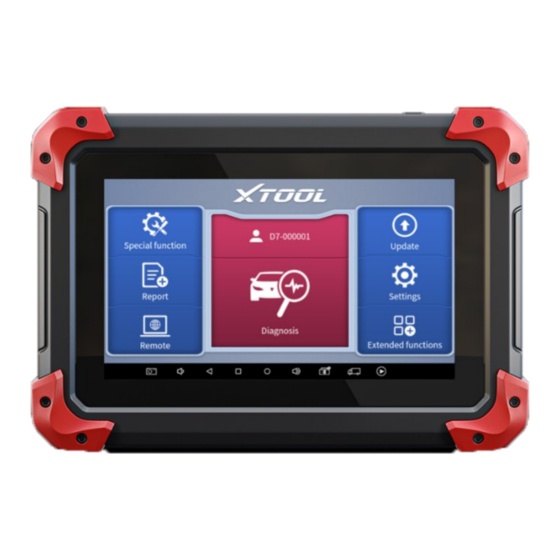
Page 23: Function Buttons
Fig 2-7 The main interface is mainly composed of Function Buttons and Navigation Buttons. The touch screen navigation is menu-driven, and you can quickly access functions by clicking on the option title and answering the dialogue window. A detailed description of the menu structure can be found in the next section Function Buttons. -
Page 24: Navigation Buttons
Enter to select a vehicle Includes special functions for car diagnosis You can view the vehicle diagnostic report In case of failure, you can control the diagnostic equipment remotely Users can upgrade the available software with one click Users can set the language, unit, Bluetooth, repair shop information,... -
Page 25: Notification Bar
Shows recently used applications Press for screenshot Decrease volume Click this button to return to the diagnostic vehicle interface Increase volume Click here to return to the diagnostic vehicle models interface NOTIFICATION BAR Slide down to open the notification bar. Users can adjust the brightness of the screen when they need it, and you can also connect Wi-Fi and so on. - Page 26 Fig 2-8...
-
Page 27: Factory Reset
FACTORY RESET When you choose to restore factory settings in the OS system, the device will automatically restart and enter the factory mode to pull the software. You can select the language in the following interface. Fig 2-9 After selecting the system language, click Next to enter the Wi- Fi connection page, as shown below:... - Page 28 Fig 2-10 Select a network to connect to on the Wi-Fi connection page. After successful network connection, the automatic system will jump to Factory mode to download the software: Fig 2-11 Once the software has been downloaded, the tablet will...
-
Page 29: Update
automatically reboot and request the system language selection again. Fig 2-11 Since restoring the factory settings will erase the user information on your device, you need to enter the email again to activate your device PDATE After activating the device, please update the software in "Update"... - Page 30 update application, open the diagnosis application and click UPDATE, shown as below: Fig 3-1 *Note: After contacting your dealer change language configuration, you need to download all the software packages on the device again...
-
Page 31: Diagnosis
(ABS), airbag system (SRS), and perform kinds of actuation tests. VEHICLE CONNECTION The diagnosis operation needs to connect the D7 smart diagnosis system to a vehicle first so that the tablet can establish correct vehicle communication. Please perform the following steps: Turn on the tablet;... -
Page 32: Diagnosis
connector should be inserted into the DLC usually located under the vehicle dashboard. The connection method is shown in the figure below: Fig 4-1 Tablet Main Test Cable OBDII-16 Connector Vehicle *Caution: Please make sure all the cables are connected tightly;... -
Page 33: Vehicle Selection
VEHICLE SELECTION D7 Smart Diagnosis System support 2 ways to access the vehicle diagnosis system. You can select "Automatic Detection" or "Manual Selection" to enter the diagnosis system. Automatic detection will... - Page 34 choose "manual selection", then you can start the diagnosis by selecting the vehicle brand, year, and model of the vehicle. Enter "manual selection", you can also diagnose the car according to the system according to your needs after selecting the model. Fig 4-3...
-
Page 35: Basic Functions
BASIC FUNCTIONS The diagnosis system supports 5 basic diagnosis functions, as follows: Read ECU Read /Clear DTCs Read Live Data Actuation Test Freeze Frame Fig 4-4 Read ECU Information: This function is to read ECU version information, which is the equivalent of "System Identification"... - Page 36 It is convenient for us to make a record in the maintenance process, and it also makes data feedback and management easier. Fig 4-5 Read Trouble Code: Read trouble codes stored in ECU.
- Page 37 Fig 4-6 *Tip: In the process of diagnosis, if the device shows “System is OK” or “No Trouble Code”, it means there is no related trouble code stored in ECU or some troubles are not under the control of ECU, most of these troubles are mechanical system troubles or executive circuit troubles, it is also possible that signal of the sensor may bias within limits, which can be judged in Live Data.
- Page 38 Fig 4-7 The trouble codes can’t be erased without eliminating all the troubles, which will cause the diagnostic tool to always read the trouble code because the code will always be saved in ECU. Suggestion: users should better not clear trouble codes, we need to record the trouble details after reading the code, which is provided as a reference for maintenance.
- Page 39 the problems such as performance characteristics offset, sensitivity reduction, can be judged in live data. Fig 4-8 Fig 4-9...
- Page 40 In the process of diagnosis, if the device shows “System is OK” or “No Trouble Code”, it means there is no related trouble code stored in ECU or some troubles are not under the control of ECU, most of these troubles are mechanical system troubles or executive circuit troubles, it is also possible that signal of the sensor may bias within limits, which can be judged in Live Data.
- Page 41 PCM responds by sending the information back to the scan tool for display. Most enhanced scan tools also can actuate relays, injectors and coils, perform system tests, etc. Users could check the individual part to see what is working properly by actuation test.
- Page 42 Some vehicles may not have the option of a freeze-frame which means that the model does not support this function.
-
Page 43: Special Functions
PECIAL UNCTIONS The D7 Smart Diagnosis System supports 23 commonly used special reset functions, allowing you to quickly access your vehicle system for various scheduled services, maintenance and reset performance, eliminating the need to reset after resolving common problems. This user manual lists some of the commonly used special reset services for your reference. -
Page 44: Oil Reset
D7 are subject to the actual special functions displayed on the device. OIL RESET Reset the Engine Oil Life System, which calculates the optimum oil life change interval based on the vehicle's driving conditions and climate. The oil life reminder must be reset each time the oil is changed so that the system can calculate when the next oil change is required. -
Page 45: Epb
Electronic Parking Brake (EPB) System reset is a popular special function. You can use this function to reset the electronic parking brake system and brake pads, which also supports the brake pad replacement (retraction, release of the brake pump), G-sensor and body angle calibration. This function has multiple uses and can safely and effectively maintain the electronic brake system. -
Page 46: Sas
Steering Angle Sensors (SAS) System Calibration permanently stores the current steering wheel position as the straight-ahead position in the SAS EEPROM. Therefore, the front wheels and the steering wheel must be set exactly to the straight-ahead position before calibration. In addition, the VIN is also read from the instrument cluster and stored permanently in the SAS EEPROM. -
Page 47: Dpf
The Diesel Particle Filter (DPF) function manages DPF regeneration, DPF component replacement teach-in and DPF teach-in after replacing the engine control unit. The ECM monitors driving style and selects a suitable time to employ regeneration. Cars driven a lot at idling speed and low load will attempt to regenerate earlier than cars driven more with higher load and speed. -
Page 48: Bms Match
The PM trap is removed or replaced. The fuel additive nozzle is removed or replaced. The catalytic oxidizer is removed or replaced. The DPF regeneration MIL is on and maintenance is performed. The DPF regeneration control module is replaced. ... -
Page 49: Throttle
without automatic function. Battery monitoring sensor. Battery matching is performed to re-match the control module and motoring sensor to detect battery power usage more accurately, which can avoid an error message displayed on the instrument panel. THROTTLE Throttle Position Sensor (TPS) Match, this function enables you to make initial settings to throttle actuators and returns the “learned”... -
Page 50: Abs Bleeding
After the tire pressure MIL turns on and maintenance is performed, the tire pressure resetting function must be performed to reset tire pressure and turn off the tire pressure MIL. Tire pressure resetting must performed after maintenance is performed in the following cases: tire pressure is too low, tire leaks, tire pressure monitoring device is replaced or installed, the tire is replaced, the tire pressure sensor is damaged, and tire is replaced for the... -
Page 51: Injector Coding
When performing ABS Bleeding, it is necessary to unscrew the exhaust screw of the ABS pump. After completing the tire pressure sensor learning, it takes a while for the fault light to go out. Tire pressure imbalance will also cause the tire pressure ... -
Page 52: Gearbox Match
GEARBOX MATCH After changing the gearbox or changing the gearbox ECU, you need to use the gearbox matching function to re-match the engine and the gearbox. *Cautions! Before resetting the gearbox, please check the gearbox control unit to ensure that there is no fault code. If there is a fault code, the gearbox memory function cannot be reset. -
Page 53: Windows Initialization
After replacing the air pump assembly; After replacing the control computer ECU. WINDOWS INITIALIZATION This function is to match the windows to restore the initial memory of the ECU and restore the automatic raising and lowering functions of the power window. Usually, when the vehicle window fails or after replacing the window glass, we need to use this function to initialize the car window. -
Page 54: Immo Service
pressing the button means that they stay indirect light, and will not turn when you turn the steering wheel. IMMO SERVICE An immobilizer is an anti-theft mechanism that prevents a vehicle’s engine from starting unless the correct ignition key or other device is present. -
Page 55: Gear Learning
ignition. To prevent the car from being used by unauthorized keys, the anti-theft key matching function must be performed so that the immobilizer control system on the car identifies and authorizes remote control keys to normally use the car. When the ignition switch key, ignition switch, combined instrument panel, ECU, BCM, or remote-control battery is replaced, anti-theft key matching must be performed. - Page 56 learning for the car. After tooth learning is successful, the MIL turns off. This function can complete the self-learning of the gearbox and improve the quality of shifting. After the engine ECU, crankshaft position sensor, or crankshaft flywheel is replaced, or the DTC 'tooth not learned' is present, tooth learning must be performed.
-
Page 57: Settings
ETTINGS Click the Settings button to adjust the default settings and view information about the D7 Smart Diagnosis System. There are seven options available in the system settings: Language Units My Workshop Info VCI Info About ... - Page 58 Fig 6-1 This will only change the language of the APP. If you want to change the system language, please go to Android Settings. How to change the language of your software? Step1: Contact your dealer and leave a message about ...
-
Page 59: Units
Step4: Back to Updates to pull all packages again UNITS You can switch the unit used by the system. D7 Smart Diagnosis System provides you with Metric, Imperial, and U.S. units. You can directly click on the unit you need, after the switch is successful, a blue checkmark will be displayed behind the unit’s name. -
Page 60: My Workshop Info
MY WORKSHOP INFO Click on My Workshop Information, you can input your workshop information here. As shown in the figure below, you just need to fill in the valid information in the corresponding column and click "SUBMIT". And then it will show your workshop information in the report when you generate a diagnostic report, including your company name, address, website, telephone, and mailbox. -
Page 61: Vci Information
VCI INFORMATION Fig 6-4 You can view the VCI information here, including the VCI firmware name, the latest firmware version, the currently used firmware version, and the VCI firmware type. The diagnosis tablet supports automatic firmware update, please make sure that the device is connected to the network when you enter the diagnostic software and the firmware will be automatically updated to the latest version. -
Page 62: About
ABOUT Tap on ABOUT, you can check the serial number and APP version on here. Fig 6-5... -
Page 63: Report
EPORT Diagnostic Report is used for viewing and printing the saved files, such as Live Data, Trouble codes or pictures generated in the process of diagnosis, users also can view a record of which cars have been previously tested. It includes 3 parts: Report ... -
Page 64: Report
you can view and delete the vehicle's diagnostic reports according to your needs. Fig 7-2 When you open the report, located in the header of the table is the studio information you filled in advance in the system setup, then the information of the vehicle, as shown as below:... - Page 65 IP address of the printer in the APP, or you can contact your dealer for help. D7 Smart Diagnosis System doesn’t provide the printer driver software, please install a third part App on the tablet if you need the print your diagnosis report.
-
Page 66: Replay
Fig 6-4 Step 4: Click the top-left corner of the screen and choose the printer you added before. Then click the button on the right to print. Fig 6-5 REPLAY This function allows you to replay the living data recorded during the diagnosis process. -
Page 67: File Manager
FILE MANAGER This function allows you to check and delete files on the device. Please use this function under the guidance of professionals. Ordinary users are not recommended to use it by themselves, as it may cause software missing or malfunctioning. -
Page 68: Remote Assistance
To obtain remote support from your partners or XTOOL After- service Center: 1. Turn on the power of the tablet. - Page 69 4. Provide your ID to the partner or XTOOL technician, and then wait for him/her to send you a remote-control request.
-
Page 70: Faq
9 FAQ Q1: FAILED TO GENERATE DIAGNOSIS REPORT 1. Currently only perform diagnostic functions, that is, read ECU information, read code and clear code, live data, freeze frame, which can trigger a diagnostic report. Other functions, such immobilization maintenance services will not be displayed in the report. 2. - Page 71 Fig 9-1 Fig 9-2...
-
Page 72: Q2: How To Print Diagnosis Report
OS settings. After the setting is completed, you can print it in the Report. Q3: FAILED TO EXTRACT FILES Since the XTOOL tablet is equipped with an Android system, you have to confirm the system type of receiver. For Android: supports transferring files via Bluetooth, USB... -
Page 73: Q4: Mailbox Supported
Q6: HOW TO GENERATE AND UPLOAD DIAGNOSTIC LOG FILES The D7 tablet will automatically generate and store the diagnostic logs. When the device is connected to the Internet, it will automatically upload all the stored diagnostic logs to the... -
Page 74: Q7: How To Switch Language
Q7: HOW TO SWITCH LANGUAGE 1. Contact your dealer and leave a message about the language you need and the S/N of your device, The technician will modify the language configuration for you in the backend system. 2. Settings->Language->Choose language 3. -
Page 75: Q9: Failed To Activate Or Register
Q9: FAILED TO ACTIVATE OR REGISTER For ‘Activation Failed’ Generally caused by network instability, please switch to a more stable network and try to activate again. For ‘Registration Failed’ Generally, it is caused by the connection timeout or the sending timeout, please check whether you have blocked the outgoing network traffic to non-US regions like China. - Page 76 ., L HENZHEN TOOLTECH NTELLIGENT Company address: 17&18/F, Building A2, Creativity City, Liuxian Avenue, Nanshan District, Shenzhen, China Factory address: 2/F, Building 12, Tangtou Third Industrial Zone, Shiyan Street, Baoan District, Shenzhen, China Service-Hotline: 0086-755-21670995/86267858 Email: marketing@xtooltech.com Fax: 0755-83461644 Website: www.xtooltech.com...
Need help?
Do you have a question about the D7 and is the answer not in the manual?
Questions and answers
Turned D7S on and a message displayed is "Application is restricted and cannot be started". What to do?
x tool 7 started updating then went to a blue screen and hasn't come on since what's wrong