Table of Contents
Advertisement
Quick Links
Advertisement
Table of Contents

Related Manuals for Xtool D8


Summary of Contents for Xtool D8
- Page 1 D8 Smart Diagnosis System User Manual Shenzhen Xtooltech Intelligent Co., LTD...
-
Page 2: Trademarks
Please read this user manual carefully before using the D8 Smart Diagnosis System. When reading the manual, please pay attention to the words “Note” or “Caution”, and read them carefully for appropriate operation. RADEMARKS is a registered trademark of Shenzhen Xtooltech Intelligent CO., LTD. -
Page 3: Copyright
(electronic, mechanical, photocopying, recording or other forms). ECLARATION This manual is designed for the usage of D8 Smart Diagnosis System, and provides operating instructions and product descriptions for users of the D8 Smart Diagnostic system. No part of this manual can be reproduced, stored in a retrieval... - Page 4 All information, specifications and illustrations in this manual are based on the latest configurations and functions available at the time of printing. Xtool reserves the right to make changes at any time without notice. PERATION NSTRUCTIONS For safe operation, please follow the instructions below: Keep the device away from heat or fumes when you using it.
-
Page 5: Cautions
Do not switch off the power or unplug the connectors during testing, otherwise you may damage the ECU and/or the Diagnostic Tablet. AUTIONS Avoid shaking or dismantling the unit as it may damage the internal components. Do not use hard or sharp objects to touch the LCD screen; ... -
Page 6: Table Of Contents
ONTENT TRADEMARKS......................I COPYRIGHT....................... II DECLARATION......................II OPERATION INSTRUCTIONS................III CAUTIONS!....................... IV AFTERSALES-SERVICES..................IV 1 GENERAL INTRODUCTION................4 Tablet........................4 Front View of Tablet ....................5 Back View of Tablet ....................6 Host Ports ....................... 7 Technical Specifications..................8 Packing List......................9 2 GETTING STARTED..................10 Guide to Activation.................... - Page 7 4 DIAGNOSIS......................23 Vehicle Connection................... 23 Diagnosis......................24 Vehicle Selection ....................25 Basic functions ...................... 30 5 SPECIAL FUNCTIONS..................37 Key Programming....................38 EEPROM Adapter..................... 39 EPB Reset......................40 OIL Light Reset....................41 SAS Reset......................41 TPS Match......................42 Injector Coding....................42 ABS Bleeding.....................
- Page 8 Seat Match......................50 Electronic Pump Activation................50 Transport Mode....................50 DIY Mode......................50 ODO Reset......................51 6 SETTINGS......................52 Language......................53 Units........................53 My Workshop Info....................54 VCI Information....................55 About........................56 7 REPORT......................58 Report........................59 8 REMOTE ASSISTANCE...................61 SHENZHEN XTOOLTECH INTELLIGENT CO., LTD........63...
-
Page 9: General Introduction
/ windows Initialization/seat matching/DIY mode) can also achieve faster and more accurate diagnosis. TABLET The main unit of the D8 is the tablet, which has a built-in VCI module, which can be directly connected to the tablet and the car... -
Page 10: Front View Of Tablet
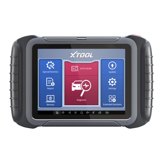
with the main test cable, without the need to connect to an external VCI box via Bluetooth. FRONT VIEW OF TABLET Fig 1-1 Tablet Front View The front of the main unit is a touchable display screen, you can use your fingers to operate on the screen to complete the car diagnosis. -
Page 11: Back View Of Tablet
BACK VIEW OF TABLET Fig 1-2 Tablet Back View Camera: 8-megapixel camera, for taking pictures. Tablet Holder: Used to support the tablet, flexible adjustment of the tablet height as needed. Nameplate: Display the basic information about tablet such as product name and model etc. Loudspeaker: It supports external sound playback.. -
Page 12: Host Ports
HOST PORTS Fig 1-3 Tablet Host Ports USB 3.0 port: Data transfer interface for tablet communication and diagnostics. VGA port: Diagnostic communication interface, which can be used for diagnosis. DC charging port: Charging port, connected to the charger can be charged. Power button: Long press to turn on/off, short press to rest/brighten the screen. -
Page 13: Technical Specifications
TECHNICAL SPECIFICATIONS Table 1-1 Specifications Item Description Android Processor Quad-core processor 1.8GHz Display 8-inch capacitive, 1024×768 resolution Connectivity Wi-Fi 8-megapixel autofocus rear camera with Camera flash Sensor Gravity sensor Audio input/ Audio Microphone/ Loudspeaker output USB3.0 Ports DC charging port ... -
Page 14: Packing List
PACKING LIST Table 1-2 Packing List Category Name Test OBD II-16 Connectors DB15 to VGA Cable and Cables USB 3.0 Cable DC12V(AC100~240V) 3A Adaptor US power cable EU power cable Main Unit P804 Tool kit Certificate of Quality Accessories Packing List User Manual Carton *Note... -
Page 15: Getting Started
ETTING TARTED GUIDE TO ACTIVATION After first time users turn on the system, the system will automatically enter the guide process and request the user to select the system operating language. Fig 2-1 After selecting the system language, click Next to enter the Wi-Fi connection page, as shown below:... - Page 16 Fig 2-2 Select a network to connect to on the Wi-Fi connection page. After successful network connection, the automatic system will jump to Factory mode to download the software: Fig 2-3...
- Page 17 Once the software has been downloaded, the tablet will automatically reboot and request the system language selection again. Fig 2-4 After setting the system language, you will enter the activation page, as shown in the figure below. You can also click the "Trial" button in the upper right corner to try it out before activation.
- Page 18 Fig 2-5 Click Start Activate to enter the activation page, as shown below: Fig 2-6...
- Page 19 A pop-up window showing Activation Success indicates that you have completed the first boot setup, click OK to enter the diagnostic system and start using the device. Fig 2-7...
-
Page 20: Main Interface
MAIN INTERFACE OPERATION SYSTEM As shown in the figure below, this interface is the main page of the operating system of the device. You can also return to this interface at any time by clicking 【 】 on the bottom navigation bar. - Page 21 D8 Smart Diagnosis System a) Browser: Click on the browser icon to enter the browser to view the official website of Xtool or search for other information. b) Gallery: Click the Gallery icon to enter the album to quickly view the pictures or screenshots stored in the device. You can...
- Page 22 Local/Home/Cleaner to clean up files. Fig 2-9 e) D8 Smart Diagnosis System: The App allows you to diagnose your vehicle and offers a range of special maintenance services.
-
Page 23: Diagnosis System Entrance
DIAGNOSIS SYSTEM ENTRANCE Once activated, you will automatically enter the diagnostic system with the following main screen. Tap on diagnosis application button on the menu, the main interface will be shown as below: Fig 2-10 The main interface is mainly composed of Function Buttons and Navigation Buttons. -
Page 24: Function Buttons
In case of failure, you can control the diagnostic equipment remotely Users can upgrade the upgradeable software with one click Users can set the language, unit, Bluetooth, repair shop information, also can view information about this software Users can view extended functions such as Xtool Cloud here... -
Page 25: Navigation Buttons
NAVIGATION BUTTONS Instructions for operating the navigation bar buttons at the bottom of the screen, as described in the table below: Table 2-3 Items Descriptions Back to previous interface Back to the main interface of Android system Shows recently used applications Press for screenshot Increase volume Click here to return to diagnostic vehicle models... -
Page 26: Notification Bar
NOTIFICATION BAR Slide down to open the notification bar. User can adjust the brightness of the screen when you need, and you can also connect Wi-Fi and so on. Fig 2-11... -
Page 27: Update
PDATE After activating the device, please update the software in "Update" first. The device will pull all currently supported software packages, and you can download them as needed. ALL software updates directly via the Internet. To access the update application, open the diagnosis application and click UPDATE, shown as below: Fig 3-1 *Note... -
Page 28: Diagnosis
(ABS), airbag system (SRS), and perform kinds of actuation tests. VEHICLE CONNECTION The diagnosis operation needs to connect the D8 smart diagnosis system to vehicle first, so that the tablet can establish correct vehicle communication. Please perform the following steps: 1 Turn on the tablet;... -
Page 29: Diagnosis
vehicle, and the main test line should be connected to the OBDII- 16 adapter and the tablet The connection method is shown in the figure below: Fig 4-1 Tablet Main Test Cable OBDII-16 Connector Vehicle *Caution: Please make sure all the cables are connected tightly; The vehicle’s DLC is not always located under the dash;... -
Page 30: Vehicle Selection
VEHICLE SELECTION The D8 intelligent diagnosis system supports the following 4 ways to access to the vehicle diagnosis system. AUTO SCAN SCAN CODE MANUAL ENTER SELECT VEHICLE BY AREA Fig 4-1 Click the VIN button in the upper left corner, you can choose to enter the vehicle diagnosis through the first 3 ways of AUTO SCAN/SCAN CODE/MANUAL ENTER. - Page 31 AUTO SCAN: It supports automatic reading of vehicle VIN code. Fig 4-2 *Note a) You also can tap on the button “AUTO SCAN” on diagnosis system entrance to use this function. b) Please make sure that the car and the device are well connected before using this function.
- Page 32 When using this function, please make sure that the light is sufficient and the bar code is not obstructed; Please make sure the wireless network environment is stable. MANUAL ENTER: It supports manual input of car VIN code. When entering the VIN code manually, make sure that the 17 characters entered are correct to avoid reading failure.
- Page 33 SELECT VEHICLE BY AREA In addition to the above 3 methods, you can also choose a car brand according to the region. You can select the vehicle model that needs to be diagnosed according to the area, as shown below: Fig 4-4 Some models provide multiple entry methods in the sub-menu, including Automatic Detection, Manual Selection and System...
- Page 34 Fig 4-5 Automatic Detection will automatically identify the vehicle's VIN code, and then read the information of your target diagnostic object. If you choose "Manual selection", then you can continue to select the vehicle brand, year, and model of the vehicle in the sub-menu to diagnosis the vehicle.
-
Page 35: Basic Functions
If you need to view the list of functions covered by the model, you can click the PDF icon at the top right of the model brand button. BASIC FUNCTIONS The diagnosis system supports 5 basic diagnosis functions, as follows: Read ECU Information ... - Page 36 Read ECU Information: This function is to read ECU version information, which is the equivalent of "System Identification" or "System information in some electronic control systems, all mean to read ECU related software and hardware versions, models and production date of diesel engine, part number, etc. It is convenient for us to make record in the maintenance process, and it also makes data feedback and management easier.
- Page 37 Read Trouble Code: Read trouble codes stored in ECU. Fig 4-6 *Tip: In the process of diagnosis, if the device shows “System is OK” or “No Trouble Code”, it means there is no related trouble code stored in ECU or some troubles are not under the control of ECU, most of these troubles are mechanical system troubles or executive circuit troubles, it is also possible that signal of the sensor may bias within limits, which can be judged in Live Data.
- Page 38 Clear Trouble Code: It allows to clear current and historical trouble codes memory in ECU, under the premise that all the troubles are eliminated. Fig 4-7 The trouble codes can’t be erased without eliminating all the troubles, which will cause the diagnostic tool always reading the trouble code because the code will always be saved in ECU.
- Page 39 Read Live Data: that is to read the parameters of running engine, such as oil pressure, temperature, engine speed, fuel oil temperature, coolant temperature, intake air temperature, etc. Based on these parameters, we can judge directly where the problem lies, which helps to narrow the scope in maintenance. For some vehicles, during their actual operation, the problems such as performance characteristics offset, sensitivity reduction, can be judged in live data.
- Page 40 stored in ECU or some troubles are not under the control of ECU, most of these troubles are mechanical system troubles or executive circuit troubles, it is also possible that signal of the sensor may bias within limits, which can be judged in Live Data. Actuation Test: mainly to judge whether these actuating components of engine are working properly.
- Page 41 The living data items supported by vehicles of different brands are not exactly the same, so the frozen frames displayed when diagnosing vehicle of different brands may also be different. Some vehicles may not have the option of frozen frame, because the model does not support this function.
-
Page 42: Special Functions
PECIAL UNCTIONS The D8 Smart Diagnosis System supports 23 commonly used special reset functions, allowing you to quickly access your vehicle system for various scheduled services, maintenance and reset performance, eliminating the need to reset after resolving common problems. This user manual lists some of the commonly used special reset services for your reference. -
Page 43: Key Programming
Due to the limitation of screenshots, the special functions shown in this picture are not complete. All special functions supported by D8 are subject to the actual special functions displayed on the device. KEY PROGRAMMING An immobilizer is an anti-theft mechanism that prevents a vehicle’s engine from starting unless the correct ignition key or other device is present. -
Page 44: Eeprom Adapter
To prevent the car being used by unauthorized keys, the anti-theft key matching function must be performed so that the immobilizer control system on the car identifies and authorizes remote control keys to normally use the car. When the ignition switch key, ignition switch, combined instrument panel, ECU, BCM, or remote-control battery is replaced, anti-theft key matching must be performed. -
Page 45: Epb Reset
EPB RESET Electronic Parking Brake (EPB) System reset is a popular special function. You can use this function to reset the electronic parking brake system and brake pads, which also supports the brake pad replacement (retraction, release of the brake pump), G-sensor and body angle calibration. -
Page 46: Oil Light Reset
OIL LIGHT RESET Reset the Engine Oil Life System, which calculates the optimum oil life change interval based on the vehicle's driving conditions and climate. The oil life reminder must be reset each time the oil is changed so that the system can calculate when the next oil change is required. -
Page 47: Tps Match
before calibration. In addition, the VIN is also read from the instrument cluster and stored permanently in the SAS EEPROM. On successful completion of calibration, the SAS fault memory is automatically cleared. To reset the steering angle, first find the relative zero-point position for the car to drive in straight line. -
Page 48: Abs Bleeding
Write injector actual code or rewrite code in the ECU to the injector code of the corresponding cylinder so as to more accurately control or correct cylinder injection quantity. After the ECU or injector is replaced, injector code of each cylinder must be confirmed or re-coded so that the cylinder can better identify injectors to accurately control fuel injection. -
Page 49: Gearbox Match
When performing ABS Bleeding, it is necessary to unscrew the exhaust screw of the ABS pump. After completing the tire pressure sensor learning, it takes a while for the fault light to go out. Tire pressure imbalance will also cause the tire pressure light to light up. GEARBOX MATCH After changing the gearbox or changing the gearbox ECU, you need to use the gearbox matching function to re-match the engine... -
Page 50: Srs Reset
the MIL turns off. This function can complete the self-learning of the gearbox and improve the quality of shifting. After the engine ECU, crankshaft position sensor, or crankshaft flywheel is replaced, or the DTC 'tooth not learned' is present, tooth learning must be performed. SRS RESET Supplemental Restrgint System (SRS) Reset allows you resets the airbag data to clear the airbag collision fault indicator. -
Page 51: Bms Match
the DPF light and “Check Engine” indicators displaying. A service regeneration can be requested in the workshop using the diagnostic tool. DPF regeneration is used to clear PM (Particulate Matter) from the DPF filter through continuous combustion oxidation mode (such as high temperature heating combustion, fuel additive or catalyst reduce PM ignition combustion) to stabilize the filter performance. -
Page 52: Air Suspension
Battery matching must be performed in the following cases: Main battery is replaced. Battery matching must be performed to clear original low battery information and prevent the related control module from detecting false information. If the related control module detects false information, it will invalidate some electric auxiliary functions, such as automatic start &... -
Page 53: Cylinder
The shock absorber is not the same height due to air leakage, maintenance, replacement, etc.; After replacing the air pump assembly; After replacing the control tablet ECU. CYLINDER This function is suitable for power balance after replacing and repairing the cylinder. -
Page 54: Tyre Refit
tire is replaced, tire pressure sensor is damaged, and tire is replaced for the car with tire pressure monitoring function. TYRE REFIT This function is used to set the size parameters of refitting or replacing tires. HEAD ADJUSTMENT This function is used to initialize the adaptive headlight system. It refers to the adaptive front lighting system (when using bi-xenon headlights at night), it can be rotated to the sides, pressing the button means that they remain direct, and do not turn when you... -
Page 55: Seat Match
SEAT MATCH This function is suitable for the matching of replacement and maintenance seats with memory function. After the seat fails or is replaced or repaired, it is generally necessary to use this function to match the seat. *Note Needed for cars with seats with memory function, general gasoline cars don’t need. ELECTRONIC PUMP ACTIVATION Use this function to activate the electronic water pump before venting the cooling system. -
Page 56: Odo Reset
this function to support the activation of the hidden functions of the car (except those that are not supported by the hardware). Different hidden functions may require different operation steps, please be sure to operate under the guidance. Cautions! The functions that the original ECU must support can be ... -
Page 57: Settings
ETTINGS Fig 6-1 Click the Settings button to adjust the default settings and view information about the D8 Smart Diagnosis System. There are seven options available in the system settings: Language Units My Workshop Info VCI Info ... -
Page 58: Language
UNITS You can switch the unit used by the system. D8 Smart Diagnosis System provides you with metric and imperial units. You can directly click on the unit when you need, after the switch is... -
Page 59: My Workshop Info
successful, a blue check mark will be shown behind the unit’s name. Fig 6-3 MY WORKSHOP INFO Click on My Workshop Information, you can input your workshop information here. As shown in the figure below, you just need to fill in the valid information in the corresponding column and click "SUBMIT". -
Page 60: Vci Information
Fig 6-4 VCI INFORMATION You can view the VCI information here, including the VCI firmware name, the latest firmware version, the currently used firmware version, and the VCI firmware type. If the current firmware version is lower than the latest firmware version, you can choose to update your firmware version and click "Update VCI Firmware"... -
Page 61: About
Fig 6-5 ABOUT Tap on ABOUT, you can check the serial number and APP version on here. - Page 62 Fig 6-6...
-
Page 63: Report
EPORT Diagnostic Report is used for viewing and printing the saved files, such as Live Data, Trouble codes or pictures generated in the process of diagnosis, users also can view a record of which cars have been previously tested. It includes 3 parts: Report ... -
Page 64: Report
REPORT This feature provides a history of diagnostic reports, where you can view and delete the vehicle's diagnostic reports according to your needs. Fig 7-2 When you open the report, located in the header of the table is the studio information you filled in advance in the system setup, then the information of the vehicle, including the diagnosis date and time, VIN number, vehicle brand, diagnosis path, etc., as shown as below:... - Page 65 Fig 7-3 As you can see, you also could click "Print PDF Report" at the bottom right corner to output the paper version of the diagnostic results. If you need to close the report, you could tap on the button “Exit”...
-
Page 66: Remote Assistance
If you encounter problems and are not able to solve them, you could open this application and ask for remote assistance. To obtain remote support from your partners or Xtool After-service Center: 1. Turn on the power of the tablet. - Page 67 4. Provide your ID to the partner or Xtool technician, and then wait for him/her to send you a remote-control request. 5. A pop-up window will be shown for asking you to confirm to allow the remote-control program to control your device.
-
Page 68: Shenzhen Xtooltech Intelligent Co., Ltd
., L HENZHEN TOOLTECH NTELLIGENT Company address: 17&18/F, Building A2, Creativity City, Liuxian Avenue, Nanshan District, Shenzhen, China Factory address: 2/F, Building 12, Tangtou Third Industrial Zone, Shiyan Street, Baoan District, Shenzhen, China Service Hotline: 0086-755-21670995/86267858 Email: marketing@Xtooltech.com Fax: 0755-83461644 Website: www.Xtooltech.com...
Need help?
Do you have a question about the D8 and is the answer not in the manual?
Questions and answers