Table of Contents
Advertisement
Advertisement
Table of Contents

Related Manuals for Xtool D8 BT


Summary of Contents for Xtool D8 BT
- Page 1 User Manual D8 BT Smart Diagnosis System Shenzhen Xtooltech Intelligent Co., LTD...
- Page 2 Please read this user manual carefully before using the D8 BT Smart Diagnosis System. When reading the manual, please pay attention to the words “Note” or “Caution”, and read them carefully for appropriate operation. RADEMARKS is a registered trademark of Shenzhen Xtooltech Intelligent CO., LTD.
-
Page 3: Copyright
(electronic, mechanical, photocopying, recording or other forms). ECLARATION This manual is designed for the usage of the D8 BT Smart Diagnosis System and provides operating instructions and product descriptions for users of the D8 BT Smart Diagnostic system. -
Page 4: Operation Instructions
All information, specifications and illustrations in this manual are based on the latest configurations and functions available at the time of printing. Xtool reserves the right to make changes at any time without notice. PERATION... - Page 5 Make sure the car is securely parked, Neutral is selected ⚫ or the selector is at P or N position to prevent the vehicle from moving when the engine starts. Do not switch off the power or unplug the connectors ⚫...
-
Page 6: Aftersales-Services
FTERSALES ERVICES E-Mail: supporting@xtooltech.com Tel: +86 755 21670995 or +86 755 86267858 (China) Official Website: www.xtooltech.com NOTE: When seeking technical support, please provide ✓ S/N of your device ✓ VIN of your vehicle Software version ✓ This will help us quickly locate your problem... -
Page 7: Table Of Contents
ONTENT TRADEMARKS ................I COPYRIGHT ................II DECLARATION ................II OPERATION INSTRUCTIONS ..........III CAUTIONS! ................IV AFTERSALES-SERVICES ............V GENERAL INTRODUCTION ..........1 1.1. Tablet ..............2 Front View of Tablet ................. 2 Back View of Tablet .................. 3 Host Ports .................... - Page 8 Diagnosis system entrance ..............15 Function Buttons ..................16 Navigation Buttons ................18 Notification Bar ..................19 UPDATE &DELETE SOFTWARE ........20 3.1. Update Software ..........20 3.2. Delete Software ........... 21 DIAGNOSIS ................ 23 4.1. Vehicle Connection ..........23 4.2.
- Page 9 5.8 GEARBOX MATCH ............. 74 5.9 GEAR LEARNING ............75 REPORT ................79 6.1. Report ..............80 6.2. Replay..............83 6.3. File Manager ............84 SETTINGS ................86 7.1. Language ............. 87 7.2. Units ..............88 7.3. Bluetooth ............. 89 7.4.
- Page 10 Q6: How to generate and upload diagnostic log files ..106 Q7: How to switch language ..........106 Q8: Failed to diagnose vehicle ........106 Q9: Failed to activate or register ........107 Q10: Failed to turn on when charging ......108 Q11: Failed to open the diagnosis app with PROMPT “Sync your device.
-
Page 11: General Introduction
ENERAL NTRODUCTION The D8 BT smart diagnostic system is an advanced scanning tool based on the Android operating system. It supports multi- language switching and is suitable for different countries and regions. The advantage of this OBDⅡscanner is not only its... -
Page 12: Tablet
1.1. TABLET The main unit of the D8 BT is the tablet, which has a built-in VCI module, which can be directly connected to the tablet and the car with the main test cable, without the need to connect to an external VCI box via Bluetooth. -
Page 13: Back View Of Tablet
The front of the main unit is a touchable display screen, you can use your fingers to operate on the screen to complete the car diagnosis. BACK VIEW OF TABLET Figure 1-2 Sample of Tablet Back View ① Camera: 8-megapixel camera, for taking pictures. ②... -
Page 14: Host Ports
③ Nameplate: Display the basic information about the tablet such as product name and model etc. ④ Loudspeaker: It supports playing external sounds. HOST PORTS Fig 1-3 Sample of Tablet Host Ports ① USB 3.0 port: Data transfer interface for tablet communication and diagnostics. -
Page 15: Vci Box
1.2. VCI BOX Fig 1-4 Sample of VCI Box ① LCD: Display the battery voltage of the vehicle ② OBD 16 pin connector: Insert the OBD- Ⅱ port on the vehicle ③ Light button: provide lighting function ④ Bluetooth Indicator: It turns blue when Bluetooth is connected successfully ⑤... -
Page 16: Specifications
1.3. SPECIFICATIONS Table 1-1 Specification Item Description Android Processor Quad-core processor 1.8GHz 8-inch capacitive, 1024×768 Display resolution ⚫ Connectivity ⚫ Wi-Fi 8-megapixel autofocus rear Camera camera with flash Sensor Gravity sensor Audio Input/ Audio Output Microphone/ Loudspeaker ⚫ USB3.0 ⚫ Ports DC charging port ⚫... -
Page 17: Packing List
Input Voltage 12V DC Operating Temperature -10~50℃ Relative Humidity < 90% Dimensions 274.0×175.0×33.8 mm 1.4. PACKING LIST Table 1-2 Packing List Category Name Tablet PC Main Units VCI Box USB 3.0 Cable DC12V(AC100~240V) 3A Adaptor US power cable EU power cable Tool kit Certificate of Quality Accessories... -
Page 18: Getting Started
ETTING TARTED 2.1. ACTIVATION After first-time users press and hold the power button to turn on the system, the system will automatically enter the guide process and request to select the language for the operating system. Figure 2-1 Sample of Selection Languages After setting the system language, you will enter the activation page, as shown in the figure below. - Page 19 "Trial" button in the upper right corner to try it out before activation. Figure 2-2 Sample of Activation (Screen 1) Click Start Activate to enter the activation page, as shown below:...
- Page 20 Figure 2-3 Sample of Activation (Screen 2) A pop-up window showing Activation Success indicates that you have completed the first boot setup, click OK to enter the diagnostic system and start using the device. Figure 2-4 Sample of Activation (Screen 3)
-
Page 21: Main Interface
2.2. MAIN INTERFACE OPERATION SYSTEM As shown in the figure below, this interface is the main page of the operating system of the device. You can also return to this interface at any time by clicking 【】on the bottom navigation bar. - Page 22 The icons on the right, from top to bottom, are browser, photo album, application square, file manager, system settings, as shown below: Table 2-1 Items Descriptions Browser Album Application Square File Explorer Settings for Android System D8 BT Smart Diagnosis System...
- Page 23 Browser: Click on the browser icon to enter the browser to view the official website of Xtool or search for other information. b) Gallery: Click the Gallery icon to enter the album to quickly view the pictures or screenshots stored in the device.
- Page 24 Figure 2-6 Sample of ES File Explorer e) D8 BT Smart Diagnosis System: The App allows you to diagnose your vehicle and offers a range of specialist maintenance services.
-
Page 25: Diagnosis System Entrance
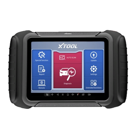
DIAGNOSIS SYSTEM ENTRANCE Once activated, you will automatically enter the diagnostic system with the following main screen. Tap on the diagnosis application button on the menu, the main interface will be shown as below: Figure 2-7 Sample of APP Main Page The main interface is mainly composed of Function Buttons and Navigation Buttons. -
Page 26: Function Buttons
on the option title and answering the dialogue window. A detailed description of the menu structure can be found in the next section Function Buttons. FUNCTION BUTTONS The following table briefly describes each function button Table 2-2 Item Description Quickly access to the vehicle system to identify the vehicle VIN code Enter to select a vehicle Includes special functions for car diagnosis... - Page 27 Users can view extended functions such as Xtool Cloud here...
-
Page 28: Navigation Buttons
NAVIGATION BUTTONS Instructions for operating the navigation bar buttons at the bottom of the screen, as described in the table below: Table 2-3 Items Descriptions Press for screenshot Decrease volume Back to the previous interface Shows recently used applications Back to the main interface of the Android system Increase volume Showing the Bluetooth states... -
Page 29: Notification Bar
NOTIFICATION BAR Slide down to open the notification bar. Users can adjust the brightness of the screen when they need it, and you can also connect Wi-Fi and so on. Figure 2-8 Sample of NOTIFICATION BAR... -
Page 30: Update &Delete Software
&D PDATE ELETE OFTWARE 3.1. UPDATE SOFTWARE After activating the device, please update the software in "Update" first. To access the update application, open the diagnosis application and click UPDATE, shown as below: Figure 3-1 Sample of Update List... -
Page 31: Delete Software
Click the magnifying glass in the upper right corner to ⚫ search for model software by keywords ⚫ Click the up arrow on the right to download the specified package ⚫ Click UPDATES All at the bottom right to download all packages NOTE: 1. - Page 32 Figure 3-2 Sample of How to Delete Vehicle Software ** When the device prompts that the memory is insufficient, you can delete the models that are not frequently used to release the memory.
-
Page 33: Diagnosis
(ABS), airbag system (SRS), and perform kinds of actuation tests. 4.1. VEHICLE CONNECTION The diagnosis operation needs to connect the D8 BT smart diagnosis system to a vehicle first so that the tablet can establish correct vehicle communication. - Page 34 Turn on the ignition switch and click the diagnostic App to test the vehicle. When the car interacts with the diagnostic program, the VCI box flashes green The connection method is shown in the figure below: Figure 4-1 Sample of How to Connect Device to Vehicle Precautions for Diagnosis ⚫...
-
Page 35: Diagnosis
ECU nameplate; 4. If the vehicle type or electronic control system to be tested is not found in the D8 BT diagnostic function, please upgrade the vehicle diagnostic software to the latest version or consult the technical service department;... - Page 36 AUTO SCAN ⚫ SCAN CODE ⚫ ⚫ MANUAL ENTER ⚫ SELECT VEHICLE BY AREA Fig 4-2 Sample of Vin Identification Click the VIN button in the upper left corner, you can choose to enter the vehicle diagnosis through the first 3 ways of AUTO SCAN/SCAN CODE/MANUAL ENTER.
- Page 37 AUTO SCAN: It supports automatic reading of vehicle VIN ⚫ code. You also can tap on the button “AUTO SCAN” on the diagnosis system entrance to use this function. Please make sure that the car and the device are well connected before using this function.
- Page 38 ⚫ SCAN CODE: It supports scanning the bar code on the vehicle nameplate through the camera to automatically read the VIN code. NOTE: When using this function, please make sure that the light is sufficient and the bar code is not obstructed; Please make sure the wireless network environment is stable.
- Page 39 Fig 4-4 Sample of Manually Inputting Vin NOTE: This function keeping the history of manually inputting the VIN code, you can directly select the history record below to confirm the vehicle information after the first manually input.
- Page 40 SELECT VEHICLE BY AREA ⚫ In addition to the above 3 methods, you can also choose a car brand according to the region. You can select the vehicle model that needs to be diagnosed according to the area, as shown below: Figure 4-5 Sample of Vehicle Selection by Ares NOTE: If you need to view the list of functions covered by the model, you can click the PDF icon at the top right of the model...
- Page 41 OBD- Ⅱ supports reading the related fault codes of PCM; DEMO, a demonstration program; Click this button to experience and learn the operation process of the diagnostic function Some models provide multiple entry methods in the sub-menu, including: ⚫ Automatic Detection Manual Selection ⚫...
-
Page 42: Basic Functions
Automatic Detection will automatically identify the vehicle's VIN code, and then read the information of your target diagnostic object. If you choose "Manual selection", then you can continue to select the vehicle brand, year, and model of the vehicle in the sub-menu to diagnosis the vehicle. Enter "System Selection", you can also diagnose the vehicle according to the system according to your needs after selecting the model. - Page 43 Figure 4-7 Sample of Basic Function ◼ Read ECU Information This function is to read ECU version information, which is the equivalent "System Identification" "System information in some electronic control systems, all mean to read ECU related software and hardware versions, models and production date of diesel engine, part number, etc.
- Page 44 convenient for us to make a record in the maintenance process, and it also makes data feedback and management easier. Figure 4-8 Sample of ECU Information...
- Page 45 Read Trouble Code ◼ Read trouble codes stored in ECU. Figure 4-9 Sample of Read DTC *Tip: In the process of diagnosis, if the device shows “System is OK” or “No Trouble Code”, it means there is no related trouble code stored in ECU or some troubles are not under the control of ECU, most of these troubles are mechanical system troubles or executive circuit troubles, it is also possible that signal of the sensor may bias within limits, which can be judged...
- Page 46 Clear Trouble Code ◼ It allows clearing current and historical trouble codes memory in ECU, under the premise that all the troubles are eliminated. Figure 4-10 Sample of Clear DTC The trouble codes can’t be erased without eliminating all the troubles, which will cause the diagnostic tool to always read the trouble code because the code will always be saved in ECU.
- Page 47 dealing with troubles, there will be no trouble code when we re-read. ◼ Read Live Data That is to read the parameters of the running engine, such as oil pressure, temperature, engine speed, fuel oil temperature, coolant temperature, intake air temperature, etc. Based on these parameters, we can judge directly where the problem lies, which helps to narrow the scope of maintenance.
- Page 48 Figure 4-11 Sample of PIDs List ⚫ Click the magnifying glass on the top right, you can search for related PIDs based on keywords...
- Page 49 Figure 4-12 Sample of the PIDs List related by Key Words ⚫ Custom Support to show the selected PIDs.
- Page 50 Figure 4-13 Sample of Custom the PIDs Click Display All, back to the page which display all PIDs Combine ⚫ Support to select multiple PIDs and click 【Combine】 to make different graphs into one chart.
- Page 51 Figure 4-14 Sample of the PIDs Combination Note: When customizing the graphs, the number of PIDs selected at a time should not exceed 5 Data recording ⚫ Supports recording the current data value in the form of text, you can view the recorded files in Reports->Data Replay. Pause ⚫...
- Page 52 Click this button to pause the timeline of timeline ◼ Actuation Test (Bi-Directional Control) Actuation test, also known as bidirectional control, is a generic term used to describe sending and receiving information between one device and another. Figure 4-15 Sample of the Actuation Test Menu...
- Page 53 The vehicle engineers responsible for designing computer control systems programmed them so a scan tool could request information or command a module to perform specific tests and functions. Some manufacturers refer to bidirectional controls as functional tests, actuator tests, inspection tests, system tests or the like.
- Page 54 (which relates to data parameters), the scan tool user initiates a request for information from the powertrain control module (PCM), and the PCM responds by sending the information back to the scan tool for display. Most enhanced scan tools also can actuate relays, injectors and coils, perform system tests, etc.
- Page 55 When the signal of the sensor is abnormal, the ECU will save the data at that moment of failure to form a freeze frame. It is usually used to analyze the reasons that may lead to car failures. The living data items supported by vehicles of different brands are not the same, so the freeze frames displayed when diagnosing vehicles of different brands may also be different.
-
Page 56: Special Functions
PECIAL UNCTIONS The D8 BT Smart Diagnosis System supports the commonly used special reset functions, allowing you to quickly access your vehicle system for various scheduled services, maintenance and reset performance, eliminating the need to reset after resolving common problems. This user manual lists some of the commonly used special reset services for your reference. -
Page 57: Oil Reset
*Note: Due to the limitation of screenshots, the special functions shown in this picture are not complete. All special functions supported by D8 BT are subject to the actual special functions displayed on the device. 5.1 OIL RESET Reset the Engine Oil Life System, which calculates the optimum oil life change interval based on the vehicle’s driving... - Page 58 Follow the instructions displayed and press OK after completing the instructions shown. Figure 5-2 Sample of oil reset function (screen 1) Enter Maintenance mileage reset menu. Input reasonable value of mileage and press OK.
-
Page 59: Epb
Figure 5-3 Sample of oil reset function (screen 2) Message of ‘Reset success’ displayed when Oil Reset function has successfully performed. 5.2 EPB Electronic Parking Brake (EPB) System reset is a popular special function. You can use this function to reset the electronic parking brake system and brake pads, which also supports the brake pad replacement (retraction, release of the brake pump), G-sensor, and body angle calibration. - Page 60 assisting in controlling brake fluid, opening and closing brake pads, setting brakes after replacing brake discs or brake pads, etc. 1. If the brake pad wears the brake pad sense line, the brake pad sense line will send a signal to the onboard tablet asking for replacing the brake pad.
- Page 61 Figure 5-4 Sample of EPB function (screen 1) Enter the Enter maintenance mode menu and release the handbrake brake. And press OK after completing the instructions shown.
- Page 62 Figure 5-5 Sample of EPB function (screen 2) Wait until the message of ‘Successful operation’ popes up. And press OK to exit the menu. Enter the Exit maintenance mode menu and wait until the message of ‘‘Successful operation’ popes up.
-
Page 63: Sas
5.3 SAS Steering Angle Sensors (SAS) System Calibration permanently stores the current steering wheel position as the straight-ahead position in the SAS EEPROM. Therefore, the front wheels and the steering wheel must be set exactly to the straight-ahead position before calibration. In addition, the VIN is also read from the instrument cluster and stored permanently in the SAS EEPROM. - Page 64 instructions displayed. Figure 5-6 Sample of SAS function (screen 1) Wait until the following instruction is displayed and press Yes after completing the instructions shown. Figure 5-7 Sample of SAS function (screen 2)
- Page 65 Follow the instructions displayed and press OK after completing the instructions shown. Figure 5-8 Sample of SAS function (screen 3) Wait until the following instruction is displayed and press OK after completing the instructions shown.
-
Page 66: Dpf
Figure 5-9 Sample of SAS function (screen 4) Message of ‘Function execution is completed’ displayed when SAS function has successfully performed. 5.4 DPF The Diesel Particle Filter (DPF) function manages DPF regeneration, DPF component replacement teach-in, and DPF teach-in after replacing the engine control module (ECM). The ECM monitors driving style and selects a suitable time to employ regeneration. - Page 67 catalyst reduce PM ignition combustion) to stabilize the filter performance. DPF regeneration may be performed in the following cases: The exhaust back pressure sensor is replaced. ⚫ The PM trap is removed or replaced. ⚫ The fuel additive nozzle is removed or replaced. ⚫...
- Page 68 Figure 5-10 Sample of DPF function (screen 1) Read the fuel tank level and make sure that it fulfills the requirement displayed. Read the carbon deposit load.
- Page 69 Choose the drive to warm up and follow the instructions listed below. And press OK after completing the instructions shown. Figure 5-11 Sample of DPF function (screen 2) Read the note carefully and follow the instructions shown on the screen. And press OK after completing the instructions shown.
- Page 70 Figure 5-12 Sample of DPF function (screen 3) Follow the instructions displayed and press OK after completing the instructions shown. Please pay attention to the Note. Figure 5-13 Sample of DPF function (screen 4)
- Page 71 Press the OK button to start the regeneration. Figure 5-14 Sample of DPF function (screen 5) 10. Wait for the value of carbon deposit to decrease until a message ‘Emergency regeneration been completed’ popes up, this process may take up to 40 minutes.
- Page 72 Figure 5-15 Sample of DPF function (screen 5)
- Page 73 11. Wait for 2 minutes to let the particulate filter cool down. Figure 5-16 Sample of DPF function (screen 6) 12. Press drop out to exit the DPF function.
-
Page 74: Bms Reset
5.5 BMS RESET The Battery Management System (BMS) allows the scan tool to evaluate the battery charge state, monitor the close-circuit current, register the battery replacement, and activate the rest state of the vehicle. This function enables you to perform a resetting operation on the monitoring unit of the vehicle battery, in which the original low battery fault information will be cleared and battery matching will be done. - Page 75 Enter the BMS Reset menu and choose relevant models according to the vehicle being tested. Turn on the ignition switch. Press OK to continue the BMS function. Enter battery capacity (within the given range) and press OK after the input. Figure 5-17 Sample of BMS function (screen 1) Enter the battery manufacturer and press OK after the input.
- Page 76 Figure 5-18 Sample of BMS function (screen 2) Enter the 10-digit battery serial number and press OK after the input. Figure 5-19 Sample of BMS function (screen 3)
-
Page 77: Throttle
5.6 THROTTLE Throttle Position Sensor (TPS) Match, this function enables you to make initial settings to throttle actuators and returns the “learned” values stored on ECU to the default state. Doing so can accurately control the actions of regulating throttle (or idle engine) to adjust the amount of air intake. - Page 78 Figure 5-20 Sample of throttle function (screen 1) Wait until all the parameters are read and displayed. Figure 5-21 Sample of throttle function (screen 2) Press the F2 button and wait until a message of ‘Match successfully’ pops up.
-
Page 79: Injector Coding
5.7 INJECTOR CODING This function can write the identification code of the fuel injector into the ECU so that the ECU can recognize and work normally. Write actual injector code or rewrite code in the ECU to the injector code of the corresponding cylinder for controlling accurately and correcting cylinder injection quantity. - Page 80 Read the note displayed carefully and press OK after the reading. Figure 5-22 Sample of injector coding function (screen 1) Read and confirm the value stored in the cylinders.
- Page 81 Figure 5-23 Sample of injector coding function (screen 2) Enter the Change the value of cylinder menu of the replaced injector(s), enter the new 5-digit value, and then press OK.
- Page 82 Figure 5-24 Sample of injector coding function (screen 3) Wait until the message ‘Write successfully’ pops up. Turn off the ignition switch. Wait until the message asked you to turn on the ignition switch.
- Page 83 Re-enter the Fuel injection nozzle injection volume adjustment menu to check whether the new value(s) are shown. Figure 5-25 Sample of injector coding function (screen 4)
-
Page 84: Gearbox Match
5.8 GEARBOX MATCH After changing the gearbox or changing the gearbox ECU, you need to use the gearbox matching function to re-match the engine and the gearbox. Before resetting the gearbox, please check the gearbox control unit to ensure that there is no fault code. If there is a fault code, the gearbox memory function cannot be reset. -
Page 85: Gear Learning
Figure 5-26 Sample of gearbox matching function (screen 1) Wait until the message ‘Successful operation’ popes up. 5.9 GEAR LEARNING The crankshaft position sensor learns crankshaft tooth machining tolerance and saves to the tablet to more accurately diagnose engine misfires. If gear learning is not performed for a car equipped with a Delphi engine, the MIL turns on after the engine is started. - Page 86 complete the self-learning of the gearbox and improve the quality of shifting. After the engine ECU, crankshaft position sensor, or crankshaft flywheel is replaced, or the DTC 'gear not learned' is present, gear learning must be performed. The operation guidelines of the Gear learning function are shown as below: Enter the Gear learning menu and choose relevant models according to the vehicle being tested.
- Page 87 Figure 5-27 Sample of gear learning function (screen 1) Read the instructions displayed and press Yes to start the learning process.
- Page 88 Figure 5-28 Sample of gear learning function (screen 2) Press the accelerator pedal down and hold it until a message of ‘The learning is successful, please release the accelerator pedal.’ pops up. Release the accelerator pedal and press OK to exit the gear learning function.
-
Page 89: Report
EPORT Diagnostic Report is used for viewing and printing the saved files, such as Live Data, Trouble codes or pictures generated in the process of diagnosis, users also can view a record of which cars have been previously tested. It includes 3 parts: Report ⚫... -
Page 90: Report
6.1. REPORT This feature provides a history of diagnostic reports, where you can view and delete the vehicle's diagnostic reports according to your needs. Figure 6-2 Sample of Report List When you open the report, located in the header of the table is the studio information you filled in advance in the system setup, then the information of the vehicle, including the... - Page 91 diagnosis date and time, VIN, vehicle brand, diagnosis path, etc., as shown as below: Figure 6-3 Sample of Report ◼ Print PDF Report As you can see, you also could click " Print PDF Report " at the bottom right corner to output the pdf report. If you need to close the report, you could tap on the button “Exit”.
- Page 92 Step 2: Back to the Android main menu, go to Settings -> Printing-> Turn printer on. Step 3: Report-> Choose report-> Print PDF Report-> Print Figure 6-4 Sample of How to Print Report, Screen 1 Step 4: Click the top-left corner of the screen and choose the printer you added before.
-
Page 93: Replay
Figure 6-5 Sample of Report, Screen 2 6.2. REPLAY This function allows you to replay the living data recorded during the diagnosis process. Figure 6-6 Sample of Data Playback, Screen 1... -
Page 94: File Manager
Before replaying the living data, please make sure you click on the "Save to Reference" button during the diagnosis Figure 6-7 Sample of Data Playback, Screen 2 6.3. FILE MANAGER This function allows you to check and delete files on the device. Please use this function under the guidance of professionals. - Page 95 Figure 6-8 Sample of File Manager...
-
Page 96: Settings
ETTINGS Figure 7-1 Sample of Settings Click the Settings button to adjust the default settings and view information about the D8 BT Smart Diagnosis System. There are seven options available in the system settings: Language ⚫ Units ⚫ My Workshop Info... -
Page 97: Language
VCI Info ⚫ About ⚫ 7.1. LANGUAGE The languages supported by this device are listed in Settings. In areas outside the English area, the default language is English and the local official language. Figure 7-2 Sample of Language Selection NOTE: The types and quantities of languages supported are subject to the actual language types displayed on the device... -
Page 98: Units
NOTE: Please be sure to download the model software again after switching the language, otherwise the diagnosis menu will be blank 7.2. UNITS You can switch the unit used by the system. D8 BT Smart Diagnosis System provides you with metric and imperial units. -
Page 99: Bluetooth
You can directly click on the unit when you need it, after the switch is successful, a blue checkmark will be shown behind the unit’s name. Figure 7-3 Sample of Units Selection 7.3. BLUETOOTH Check your VCI box bluetooth name here and pair it... -
Page 100: My Workshop Info
Figure 7-4 Sample of Units Selection 7.4. MY WORKSHOP INFO Click on My Workshop Information, you can input your workshop information here. As shown in the figure below, you just need to fill in the valid information in the corresponding column and click "SUBMIT". -
Page 101: Vci Firmware Information
Figure 7-5 Sample of W Information orkshop 7.5. VCI FIRMWARE INFORMATION You can view the VCI firmware information here, including the VCI firmware name, the latest firmware version, the currently used firmware version, and the VCI firmware type. -
Page 102: About
Figure 7-6 Sample of VCI Firmware Information NOTE: To view the VCI firmware information, you need to enter the diagnostic package first to get the VCI box to work. 7.6. ABOUT Tap on ABOUT, you can check the serial number and APP version on here. - Page 103 Figure 7-7 Sample of About Information...
-
Page 104: Factory Reset
ACTORY ESET After first-time users turn on the system, the system will automatically enter the guide process and request the user to select the system operating language. Figure 8-1 Sample of Selecting Languages After selecting the system language, click Next to enter the Wi- Fi connection page, as shown below:... - Page 105 Figure 8-2 Sample of Selecting Wi-Fi Select a network to connect to on the Wi-Fi connection page. After successful network connection, the automatic system will jump to Factory mode to download the software:...
- Page 106 Figure 8-3 Sample of Factory Mode Once the software has been downloaded, the tablet will automatically reboot and request the system language selection again. Figure 8-4 Sample of Selecting Languages,Screen2 After setting the system language, you will enter the activation page, as shown in the figure below.
- Page 107 Figure 8-5 Sample of Activation, Screen 1 Click Start Activate to enter the activation page, as shown below:...
- Page 108 Figure 8-6 Sample of Activation, Screen 2 A pop-up window showing Activation Success indicates that you have completed the first boot setup, click OK to enter the diagnostic system and start using the device. Figure 8-7 Sample of Activation, Screen 3...
-
Page 109: Remote Assistance
If you encounter problems and are not able to solve them, you could open this application and ask for remote assistance. To obtain remote support from your partners or Xtool After- service Center: 1. Turn on the power of the tablet. - Page 110 4. Provide your ID to the partner or Xtool technician, and then wait for him/her to send you a remote-control request.
- Page 111 Figure 9-1 Sample of Activating Team Viewer, Screen 1...
-
Page 112: Faq
10 FAQ Q1: FAILED TO GENERATE DIAGNOSIS REPORT 1. Currently only perform diagnostic functions, that is, read ECU information, read code and clear code, live data, freeze frame, which can trigger a diagnostic report. Other functions, such as immobilization and maintenance services will not be displayed in the report. - Page 113 ⚫ Sample as follows: Fig 9-1 Sample1: How to clear APP cache...
-
Page 114: Q2: How To Print Diagnosis Report
Fig 9-3 Sample1: How to clear APP cache Q2: HOW TO PRINT DIAGNOSIS REPORT The XTOOL device is compatible with third-party print drivers. You can download the printer driver you need in the browser that comes with the tablet to install it, and then set your printer in the OS settings. -
Page 115: Q3: Failed To Extract Files
Q3: FAILED TO EXTRACT FILES Since the XTOOL tablet is equipped with an Android system, you have to confirm the system type of receiver. For Android: supports transferring files via Bluetooth, USB cable, etc.; For IOS: only supports transferring files through a wired connection (Bluetooth connection is not available). -
Page 116: Q6: How To Generate And Upload Diagnostic Log Files
Q6: HOW TO GENERATE AND UPLOAD DIAGNOSTIC LOG FILES The A80 tablet will automatically generate and store the diagnostic logs. When the device is connected to the Internet, it will automatically upload all the stored diagnostic logs to the backend system. Q7: HOW TO SWITCH LANGUAGE 1. -
Page 117: Q9: Failed To Activate Or Register
equipped with a VCI box, please check the status of the VCI box indicator. 3. Confirm whether you have entered the correct diagnosis menu. 4. Confirm whether the AUTO-SCAN function can assist you to enter the correct diagnosis menu, or whether the OBDII function works. -
Page 118: Q10: Failed To Turn On When Charging
Q10: FAILED TO TURN ON WHEN CHARGING In the charging state, you need to first press the power button to light up the screen (showing the charging status). Then press and hold the power button for 4-5 seconds until the boot animation is shown on screen. -
Page 119: Q12: Failed To Enter Vehicle Menu
Q12: FAILED TO ENTER VEHICLE MENU If you encounter the following two prompts, please delete the package and download it again to diagnose ⚫ ‘Failed’ ⚫ ‘License exception’... -
Page 120: Shenzhen Xtooltech Intelligent Co., Ltd
., L HENZHEN TOOLTECH NTELLIGENT Company address: 17&18/F, Building A2, Creativity City, Liuxian Avenue, Nanshan District, Shenzhen, China Factory address: 2/F, Building 12, Tangtou Third Industrial Zone, Shiyan Street, Baoan District, Shenzhen, China Service-Hotline: 0086-755-21670995/86267858 Email: marketing@Xtooltech.com Fax: 0755-83461644 Website: www.Xtooltech.com...
Need help?
Do you have a question about the D8 BT and is the answer not in the manual?
Questions and answers
Does this unit display standard range information on screen