Table of Contents
Advertisement
Quick Links
Advertisement
Table of Contents

Subscribe to Our Youtube Channel
Related Manuals for Xtool H6EB


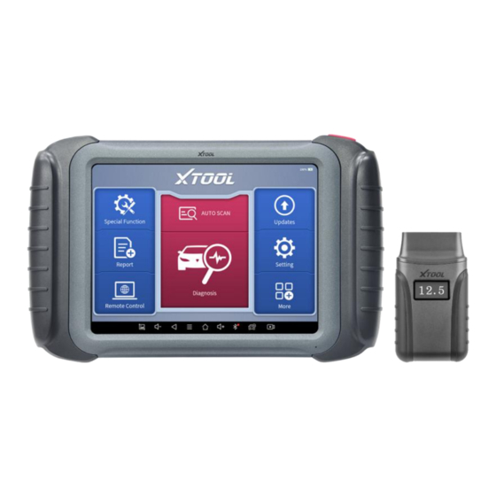
Summary of Contents for Xtool H6EB
- Page 1 User Manual H6EB Smart Diagnosis System Shenzhen Xtooltech Intelligent Co., LTD...
-
Page 2: Copyright
(electronic, mechanical, photocopying, recording or other forms). Declaration This manual is designed for the usage of the H6EB Smart Diagnosis System and provides operating instructions and product descriptions for users of the H6EB Smart Diagnostic system. -
Page 3: Operation Instructions
Xtool. Use the device only as described in this manual. Xtool is not responsible for any consequences of violating the laws and regulations caused by using the product or its data information... -
Page 4: Cautions
Do not switch off the power or unplug the connectors during testing, otherwise, you may damage the ECU and/or the Diagnostic Tablet. AUTIONS Avoid shaking or dismantling the unit as it may damage the internal components. Do not use hard or sharp objects to touch the LCD screen; ... -
Page 5: Table Of Contents
ONTENT TRADEMARKS...................I COPYRIGHT....................I DECLARATION..................I OPERATION INSTRUCTIONS...............II CAUTIONS!....................III AFTERSALES-SERVICES..............III GENERAL INTRODUCTION............1 1.1.Tablet................... 1 Front View of Tablet................2 Back View of Tablet................3 Host Ports................... 4 1.2.VCI Box..................5 1.3.Specifications................6 1.4.Packing List.................7 GETTING STARTED.................8 2.1.Activation..................8 2.2.Main Interface................10 Operation system................10 Diagnosis system entrance............13 Function Buttons................14 Navigation Buttons................ - Page 6 3.1.Update Software..............17 3.2.Delete Software................18 DIAGNOSIS..................19 4.1.Vehicle Connection..............19 4.2.Diagnosis.................. 20 Vehicle Selection................20 Basic functions................. 25 SPECIAL FUNCTIONS..............35 5.1 OIL RESET................36 5.2 EPB.................... 38 5.3 SAS.................... 39 5.4 DPF.................... 43 5.5 BMS RESET................47 5.6 THROTTLE................49 5.7 INJECTOR CODING............... 50 5.8 GEARBOX MATCH..............53 5.9 GEAR LEARNING..............
- Page 7 7.3.Bluetooth................... 65 7.4.My Workshop Info..............65 7.5.VCI Firmware Information............66 7.6.About....................FACTORY RESET................68 REMOTE ASSISTANCE..............71 10 FAQ....................73 Q1: Failed to generate diagnosis report........73 Q2: How to print diagnosis report..........74 Q3: Failed to extract files.............. 75 Q4: Mailbox supported..............75 Q5: How to make an appointment for remote support.....
-
Page 8: General Introduction
Please confirm the OBD connector specifications configured on your car before connecting. 1.1. TABLET The main unit of the H6EB is the tablet, which has a built-in VCI module, which can be directly connected to the tablet and the car with... -
Page 9: Front View Of Tablet
the main test cable, without the need to connect to an external VCI box via Bluetooth. FRONT VIEW OF TABLET Figure 1-1 Sample of Tablet Front View The front of the main unit is a touchable display screen, you can use your fingers to operate on the screen to complete the car diagnosis. -
Page 10: Back View Of Tablet
BACK VIEW OF TABLET ① ② ③ Figure 1-2 Sample of Tablet Back View Camera: 8-megapixel camera, for taking pictures. Tablet Holder: Used to support the tablet, flexible adjustment of the tablet height as needed. Nameplate: Display the basic information about the tablet such as product name and model etc. -
Page 11: Host Ports
Fig 1-3 Sample of Tablet Host Ports USB 3.0 port: Data transfer port *Please do not use other non-xtool UBS cable with this port! VGA port: A reserved interface can be used for charging. DC charging port: Charging port, connected to the charger can be charged. -
Page 12: Vci Box
1.2. VCI BOX Fig 1-4 Sample of VCI Box LCD: Display the battery voltage of the vehicle OBD 16 pin connector: Insert the OBD-Ⅱ port on the vehicle Light button: provide lighting function Bluetooth Indicator: It turns blue when Bluetooth is connected successfully Power Indicator: It turns red when power is on Vehicle Indicator: The green light flashes when the VCI box... -
Page 13: Specifications
1.3. SPECIFICATIONS Table 1-1 Specification Item Description Android Processor Quad-core processor 1.8GHz Display 8-inch capacitive, 1024×768 resolution Connectivity Wi-Fi 8-megapixel autofocus rear camera with Camera flash Sensor Gravity sensor Audio Input/ Audio Output Microphone/ Loudspeaker USB3.0 Ports DC charging port ... -
Page 14: Packing List
Operating Temperature -10~50℃ Relative Humidity < 90% Dimensions 274.0×175.0×33.8 mm 1.4. PACKING LIST Table 1-2 Packing List Category Name Tablet PC Main Units VCI Box USB 3.0 Cable DC12V(AC100~240V) 3A Adaptor US power cable EU power cable Tool kit Certificate of Quality Accessories Packing List User Manual... -
Page 15: Getting Started
ETTING TARTED 2.1. ACTIVATION After first-time users press and hold the power button to turn on the system, the system will automatically enter the guide process and request to select the language for the operating system. Figure 2-1 Sample of Selection Languages After setting the system language, you will enter the activation page, as shown in the figure below. - Page 16 Figure 2-2 Sample of Activation (Screen 1) Click Start Activate to enter the activation page, as shown below: Figure 2-3 Sample of Activation (Screen 2) A pop-up window showing Activation Success indicates that you have completed the first boot setup, click OK to enter the diagnostic system and start using the device.
-
Page 17: Main Interface
Figure 2-4 Sample of Activation (Screen 3) 2.2. MAIN INTERFACE OPERATION SYSTEM As shown in the figure below, this interface is the main page of the operating system of the device. You can also return to this interface at any time by clicking 【】on the bottom navigation bar. Figure 2-5 Sample of OS Main page... - Page 18 Table 2-1 Items Descriptions Browser Album Application Square File Explorer Settings for Android System H6EB Smart Diagnosis System Browser: Click on the browser icon to enter the browser to view the official website of Xtool or search for other information.
- Page 19 Local/Home/Cleaner to clean up files. Figure 2-6 Sample of ES File Explorer H6EB Smart Diagnosis System: The App allows you to diagnose your vehicle and offers a range of specialist maintenance services.
-
Page 20: Diagnosis System Entrance
DIAGNOSIS SYSTEM ENTRANCE Once activated, you will automatically enter the diagnostic system with the following main screen. Tap on the diagnosis application button on the menu, the main interface will be shown as below: Figure 2-7 Sample of APP Main Page The main interface is mainly composed of Function Buttons and Navigation Buttons. -
Page 21: Function Buttons
In case of failure, you can control the diagnostic equipment remotely Users can upgrade the upgradeable software with one click Users can set the language, unit, Bluetooth, repair shop information, also can view information about this software Users can view extended functions such as Xtool Cloud here... -
Page 22: Navigation Buttons
NAVIGATION BUTTONS Instructions for operating the navigation bar buttons at the bottom of the screen, as described in the table below: Table 2-3 Items Descriptions Press for screenshot Decrease volume Back to the previous interface Shows recently used applications Back to the main interface of the Android system Increase volume Showing the Bluetooth states Click this button to return to the diagnostic vehicle... -
Page 23: Notification Bar
NOTIFICATION BAR Slide down to open the notification bar. Users can adjust the brightness of the screen when they need it, and you can also connect Wi-Fi and so on. Figure 2-8 Sample of NOTIFICATION BAR... -
Page 24: Update &Delete Software
&D PDATE ELETE OFTWARE 3.1. UPDATE SOFTWARE After activating the device, please update the software in "Update" first. To access the update application, open the diagnosis application and click UPDATE, shown as below: Figure 3-1 Sample of Update List Click the magnifying glass in the upper right corner to search for ... -
Page 25: Delete Software
3.2. DELETE SOFTWARE Long-press the unwanted software until it has been selected, then click the Delete button shown on the upper part of the screen. And you can select and delete multiple software at once. Figure 3-2 Sample of How to Delete Vehicle Software ** When the device prompts that the memory is insufficient, you can delete the models that are not frequently used to release the memory. -
Page 26: Diagnosis
(ABS), airbag system (SRS), and perform kinds of actuation tests. 4.1. VEHICLE CONNECTION The diagnosis operation needs to connect the H6EB smart diagnosis system to a vehicle first so that the tablet can establish correct vehicle communication. Please perform the following steps: ... -
Page 27: Diagnosis
5. It is forbidden to use wiring harnesses other than Xtool for connection testing to avoid unnecessary losses; 6. In the communication between the H6EB Smart Diagnosis System and the vehicle, it is forbidden to shut down directly. - Page 28 MANUAL ENTER SELECT VEHICLE BY AREA Fig 4-2 Sample of Vin Identification Click the VIN button in the upper left corner, you can choose to enter the vehicle diagnosis through the first 3 ways of AUTO SCAN/SCAN CODE/MANUAL ENTER. AUTO SCAN: It supports automatic reading of vehicle VIN code.
- Page 29 Fig 4-3 Sample of AUTOSCAN SCAN CODE: It supports scanning the bar code on the vehicle nameplate through the camera to automatically read the VIN code. NOTE: When using this function, please make sure that the light is sufficient and the bar code is not obstructed; Please make sure the wireless network environment is stable.
- Page 30 Fig 4-4 Sample of Manually Inputting Vin NOTE: This function keeping the history of manually inputting the VIN code, you can directly select the history record below to confirm the vehicle information after the first manually input. SELECT VEHICLE BY AREA In addition to the above 3 methods, you can also choose a car brand according to the region.
- Page 31 Figure 4-5 Sample of Vehicle Selection by Ares NOTE: If you need to view the list of functions covered by the model, you can click the PDF icon at the top right of the model brand button. OBD- Ⅱ supports reading the related fault codes of PCM; DEMO, a demonstration program;...
-
Page 32: Basic Functions
Figure 4-6 Sample of Diagnosis Method Selection Automatic Detection will automatically identify the vehicle's VIN code, and then read the information of your target diagnostic object. If you choose "Manual selection", then you can continue to select the vehicle brand, year, and model of the vehicle in the sub-menu to diagnosis the vehicle. - Page 33 Figure 4-7 Sample of Basic Function Read ECU Information This function is to read ECU version information, which is the equivalent of "System Identification" or "System information in some electronic control systems, all mean to read ECU related software and hardware versions, models and production date of diesel engine, part number, etc.
- Page 34 Figure 4-8 Sample of ECU Information Read Trouble Code Read trouble codes stored in ECU. Figure 4-9 Sample of Read DTC...
- Page 35 *Tip: In the process of diagnosis, if the device shows “System is OK” or “No Trouble Code”, it means there is no related trouble code stored in ECU or some troubles are not under the control of ECU, most of these troubles are mechanical system troubles or executive circuit troubles, it is also possible that signal of the sensor may bias within limits, which can be judged in Live Data.
- Page 36 Read Live Data That is to read the parameters of the running engine, such as oil pressure, temperature, engine speed, fuel oil temperature, coolant temperature, intake air temperature, etc. Based on these parameters, we can judge directly where the problem lies, which helps to narrow the scope of maintenance.
- Page 37 Figure 4-12 Sample of the PIDs List related by Key Words Custom Support to show the selected PIDs. Figure 4-13 Sample of Custom the PIDs...
- Page 38 Click Display All, back to the page which display all PIDs Combine Support to select multiple PIDs and click 【Combine】 to make different graphs into one chart. Figure 4-14 Sample of the PIDs Combination Note: When customizing the graphs, the number of PIDs selected at a time should not exceed 5 Data recording ...
- Page 39 Actuation Test (Bi-Directional Control) Actuation test, also known as bidirectional control, is a generic term used to describe sending and receiving information between one device and another. Figure 4-15 Sample of the Actuation Test Menu The vehicle engineers responsible for designing computer control systems programmed them so a scan tool could request information or command a module to perform specific tests and functions.
- Page 40 Figure 4-16 Sample of the Actuation Test This function allows the device to send information to and receive information from, vehicle control modules. For example, in the case of OBD II generic information Mode 1 (which relates to data parameters), the scan tool user initiates a request for information from the powertrain control module (PCM), and the PCM responds by sending the information back to the scan tool for display.
- Page 41 Figure 4-17 Sample of the Freeze Frame When the signal of the sensor is abnormal, the ECU will save the data at that moment of failure to form a freeze frame. It is usually used to analyze the reasons that may lead to car failures. The living data items supported by vehicles of different brands are not the same, so the freeze frames displayed when diagnosing vehicles of different brands may also be different.
-
Page 42: Special Functions
PECIAL UNCTIONS The H6EB Smart Diagnosis System supports the commonly used special reset functions, allowing you to quickly access your vehicle system for various scheduled services, maintenance and reset performance, eliminating the need to reset after resolving common problems. This user manual lists some of the commonly used special reset services for your reference. -
Page 43: Oil Reset
All special functions supported by H6EB are subject to the actual special functions displayed on the device. 5.1 OIL RESET Reset the Engine Oil Life System, which calculates the optimum oil life change interval based on the vehicle’s driving conditions and climate. - Page 44 Figure 5-2 Sample of oil reset function (screen 1) Enter Maintenance mileage reset menu. Input reasonable value of mileage and press OK. Figure 5-3 Sample of oil reset function (screen 2) Message of ‘Reset success’ displayed when Oil Reset function has successfully performed.
-
Page 45: Epb
5.2 EPB Electronic Parking Brake (EPB) System reset is a popular special function. You can use this function to reset the electronic parking brake system and brake pads, which also supports the brake pad replacement (retraction, release of the brake pump), G-sensor, and body angle calibration. -
Page 46: Sas
Figure 5-4 Sample of EPB function (screen 1) Enter the Enter maintenance mode menu and release the handbrake brake. And press OK after completing the instructions shown. Figure 5-5 Sample of EPB function (screen 2) Wait until the message of ‘Successful operation’ popes up. And press OK to exit the menu. - Page 47 reference, the ECU can calculate the accurate angle for left and right steering. After replacing the steering angle position sensor, replacing steering mechanical parts (such as steering gearbox, steering column, end tie rod, steering knuckle), performing four-wheel alignment, or recovering the car body, you must reset the steering angle.
- Page 48 Figure 5-7 Sample of SAS function (screen 2)
- Page 49 Follow the instructions displayed and press OK after completing the instructions shown. Figure 5-8 Sample of SAS function (screen 3) Wait until the following instruction is displayed and press OK after completing the instructions shown. Figure 5-9 Sample of SAS function (screen 4) Message of ‘Function execution is completed’...
-
Page 50: Dpf
5.4 DPF The Diesel Particle Filter (DPF) function manages DPF regeneration, DPF component replacement teach-in, and DPF teach-in after replacing the engine control module (ECM). The ECM monitors driving style and selects a suitable time to employ regeneration. Vehicles driven a lot at idling speed and low load will attempt to regenerate earlier than vehicles driven more with higher load and speed. - Page 51 Figure 5-10 Sample of DPF function (screen 1) Read the fuel tank level and make sure that it fulfills the requirement displayed. Read the carbon deposit load. Choose the drive to warm up and follow the instructions listed below. And press OK after completing the instructions shown. Figure 5-11 Sample of DPF function (screen 2)
- Page 52 Read the note carefully and follow the instructions shown on the screen. And press OK after completing the instructions shown. Figure 5-12 Sample of DPF function (screen 3) Follow the instructions displayed and press OK after completing the instructions shown. Please pay attention to the Note. Figure 5-13 Sample of DPF function (screen 4)
- Page 53 Press the OK button to start the regeneration. Figure 5-14 Sample of DPF function (screen 5) 10. Wait for the value of carbon deposit to decrease until a message of ‘Emergency regeneration has been completed’ popes up, this process may take up to 40 minutes. Figure 5-15 Sample of DPF function (screen 5)
-
Page 54: Bms Reset
11. Wait for 2 minutes to let the particulate filter cool down. Figure 5-16 Sample of DPF function (screen 6) 12. Press drop out to exit the DPF function. 5.5 BMS RESET The Battery Management System (BMS) allows the scan tool to evaluate the battery charge state, monitor the close-circuit current, register the battery replacement, and activate the rest state of the vehicle. - Page 55 The operation guidelines of the BMS Reset function are shown as below: Enter the BMS Reset menu and choose relevant models according to the vehicle being tested. Turn on the ignition switch. Press OK to continue the BMS function. Enter battery capacity (within the given range) and press OK after the input.
-
Page 56: Throttle
Enter the 10-digit battery serial number and press OK after the input. Figure 5-19 Sample of BMS function (screen 3) 5.6 THROTTLE Throttle Position Sensor (TPS) Match, this function enables you to make initial settings to throttle actuators and returns the “learned” values stored on ECU to the default state. -
Page 57: Injector Coding
Figure 5-20 Sample of throttle function (screen 1) Wait until all the parameters are read and displayed. Figure 5-21 Sample of throttle function (screen 2) Press the F2 button and wait until a message of ‘Match successfully’ pops up. 5.7 INJECTOR CODING This function can write the identification code of the fuel injector into the ECU so that the ECU can recognize and work normally. - Page 58 injector code or rewrite code in the ECU to the injector code of the corresponding cylinder for controlling accurately and correcting cylinder injection quantity. After the ECU or injector is replaced, the injector code of each cylinder must be confirmed or re-coded so that the cylinder can better identify injectors to accurately control fuel injection.
- Page 59 Read and confirm the value stored in the cylinders. Figure 5-23 Sample of injector coding function (screen 2) Enter the Change the value of cylinder menu of the replaced injector(s), enter the new 5-digit value, and then press OK. Figure 5-24 Sample of injector coding function (screen 3) Wait until the message ‘Write successfully’...
-
Page 60: Gearbox Match
Re-enter the Fuel injection nozzle injection volume adjustment menu to check whether the new value(s) are shown. Figure 5-25 Sample of injector coding function (screen 4) 5.8 GEARBOX MATCH After changing the gearbox or changing the gearbox ECU, you need to use the gearbox matching function to re-match the engine and the gearbox. -
Page 61: Gear Learning
Figure 5-26 Sample of gearbox matching function (screen 1) Wait until the message ‘Successful operation’ popes up. 5.9 GEAR LEARNING The crankshaft position sensor learns crankshaft tooth machining tolerance and saves to the tablet to more accurately diagnose engine misfires. If gear learning is not performed for a car equipped with a Delphi engine, the MIL turns on after the engine is started. - Page 62 Read carefully and complete the requisites listed before performing the gear learning function. And press OK after completing the instructions shown Figure 5-27 Sample of gear learning function (screen 1) Read the instructions displayed and press Yes to start the learning process.
-
Page 63: Report
Press the accelerator pedal down and hold it until a message of ‘The learning is successful, please release the accelerator pedal.’ pops up. Release the accelerator pedal and press OK to exit the gear learning function. EPORT Diagnostic Report is used for viewing and printing the saved files, such as Live Data, Trouble codes or pictures generated in the process of diagnosis, users also can view a record of which cars have been previously tested. -
Page 64: Report
Figure 6-1 Sample of Report 6.1. REPORT This feature provides a history of diagnostic reports, where you can view and delete the vehicle's diagnostic reports according to your needs. Figure 6-2 Sample of Report List When you open the report, located in the header of the table is the studio information you filled in advance in the system setup, then the information of the vehicle, including the diagnosis date and time, VIN, vehicle brand, diagnosis path, etc., as shown as below:... - Page 65 Figure 6-3 Sample of Report Print PDF Report As you can see, you also could click " Print PDF Report " at the bottom right corner to output the pdf report. If you need to close the report, you could tap on the button “Exit”. Please follow the below steps to print your report▼...
-
Page 66: Replay
Figure 6-4 Sample of How to Print Report, Screen 1 Step 4: Click the top-left corner of the screen and choose the printer you added before. Then click the button on the right to print. Figure 6-5 Sample of Report, Screen 2 6.2. - Page 67 Figure 6-6 Sample of Data Playback, Screen 1 Before replaying the living data, please make sure you click on the "Save to Reference" button during the diagnosis Figure 6-7 Sample of Data Playback, Screen 2...
-
Page 68: File Manager
6.3. FILE MANAGER This function allows you to check and delete files on the device. Please use this function under the guidance of professionals. Ordinary users are not recommended to use it by themselves! Figure 6-8 Sample of File Manager... -
Page 69: Settings
ETTINGS Figure 7-1 Sample of Settings Click the Settings button to adjust the default settings and view information about the H6EB Smart Diagnosis System. There are seven options available in the system settings: Language Units My Workshop Info ... -
Page 70: Language
LANGUAGE 7.1. The languages supported by this device are listed in Settings. In areas outside the English area, the default language is English and the local official language. Figure 7-2 Sample of Language Selection NOTE: The types and quantities of languages supported are subject to the actual language types displayed on the device Users can switch between English and local official languages on the device by themselves. -
Page 71: Units
UNITS 7.2. You can switch the unit used by the system. H6EB Smart Diagnosis System provides you with metric and imperial units. You can directly click on the unit when you need it, after the switch is successful, a blue checkmark will be shown behind the unit’s name. -
Page 72: Bluetooth
BLUETOOTH 7.3. Check your VCI box bluetooth name here and pair it Figure 7-4 Sample of Bluetooth Selection 7.4. MY WORKSHOP INFO Click on My Workshop Information, you can input your workshop information here. As shown in the figure below, you just need to fill in the valid information in the corresponding column and click "SUBMIT". -
Page 73: Vci Firmware Information
Figure 7-5 Sample of W orkshop Information 7.5. VCI FIRMWARE INFORMATION You can view the VCI firmware information here, including the VCI firmware name, the latest firmware version, the currently used firmware version, and the VCI firmware type. Figure 7-6 Sample of VCI Firmware Information... - Page 74 NOTE: To view the VCI firmware information, you need to enter the diagnostic package first to get the VCI box to work. 7.6. ABOUT Tap on ABOUT, you can check the serial number and APP version on here. Figure 7-7 Sample of About Information...
-
Page 75: Factory Reset
ACTORY ESET After first-time users turn on the system, the system will automatically enter the guide process and request the user to select the system operating language. Figure 8-1 Sample of Selecting Languages After selecting the system language, click Next to enter the Wi-Fi connection page, as shown below: Figure 8-2 Sample of Selecting Wi-Fi... - Page 76 Select a network to connect to on the Wi-Fi connection page. After successful network connection, the automatic system will jump to Factory mode to download the software: Figure 8-3 Sample of Factory Mode Once the software has been downloaded, the tablet will automatically reboot and request the system language selection again.
- Page 77 After setting the system language, you will enter the activation page, as shown in the figure below. You can also click the "Trial" button in the upper right corner to try it out before activation. Figure 8-5 Sample of Activation, Screen 1 Click Start Activate to enter the activation page, as shown below: Figure 8-6 Sample of Activation, Screen 2...
-
Page 78: Remote Assistance
PC through the TeamViewer software, thereby obtaining temporary remote support from Xtool's technical support centre. Tablets and mobile devices running TeamViewer are identified by a globally unique ID. When the remote application is started for the first time, the ID will be automatically generated according to the hardware characteristics and will not be changed in the future. - Page 79 4. Provide your ID to the partner or Xtool technician, and then wait for him/her to send you a remote-control request. 5. A pop-up window will be shown asking you to confirm to allow the remote-control program to control your device.
-
Page 80: Faq
10 FAQ Q1: FAILED TO GENERATE DIAGNOSIS REPORT 1. Currently only perform diagnostic functions, that is, read ECU information, read code and clear code, live data, freeze frame, which can trigger a diagnostic report. Other functions, such as immobilization and maintenance services will not be displayed in the report. -
Page 81: Q2: How To Print Diagnosis Report
Fig 9-3 Sample1: How to clear APP cache Q2: HOW TO PRINT DIAGNOSIS REPORT The XTOOL device is compatible with third-party print drivers. You can download the printer driver you need in the browser that comes with the tablet to install it, and then set your printer in the OS settings. After... -
Page 82: Q3: Failed To Extract Files
Q3: FAILED TO EXTRACT FILES Since the XTOOL tablet is equipped with an Android system, you have to confirm the system type of receiver. For Android: supports transferring files via Bluetooth, USB cable, etc.; For IOS: only supports transferring files through a wired connection (Bluetooth connection is not available). -
Page 83: Q9: Failed To Activate Or Register
4. Confirm whether the AUTO-SCAN function can assist you to enter the correct diagnosis menu, or whether the OBDII function works. 5. Check whether the software is the latest version, if not, please update to the latest version first. Q9: FAILED TO ACTIVATE OR REGISTER For ‘Activation Failed’... - Page 84 ‘Failed’ ‘License exception’ LIMITED ONE YEAR WARRANTY...
-
Page 85: Warranty & Services
ERVICES Shenzhen Xtooltech Intelligent Co., LTD.(the Company) warrants to the original retail purchaser of this XTOOL device that should this product or any part thereof during normal usage and under normal conditions be proven defective in material or workmanship that results in product... - Page 86 ., L HENZHEN TOOLTECH NTELLIGENT Company address: 17&18/F, Building A2, Creativity City, Liuxian Avenue, Nanshan District, Shenzhen, China Factory address: 2/F, Building 12, Tangtou Third Industrial Zone, Shiyan Street, Baoan District, Shenzhen, China Service-Hotline: 0086-755-21670995/86267858 Email: marketing@Xtooltech.com Fax: 0755-83461644 Website: www.Xtooltech.com...
Need help?
Do you have a question about the H6EB and is the answer not in the manual?
Questions and answers