
Related Manuals for Xtool H6 Elite Smart


Summary of Contents for Xtool H6 Elite Smart
- Page 1 User Manual H6 Elite Smart Diagnostics System Shenzhen Xtooltech Intelligent Co., LTD...
-
Page 2: Copyright
Shenzhen Xtooltech Intelligent CO., LTD.In countries where the trademarks, service marks, domain names, logos and the name of the company are not registered, Xtool claims that it still reserves the ownership of the unregistered trademarks, service marks, domain names, logos and the company name. -
Page 3: Operation Instructions
Xtool shall not be liable for any incidental or consequential damages or for any economic consequential damages arising from the accidents of individual users and the third parties, misuse or abuse of the device, unauthorized change or repair of the device, or the failure made by the user not to use the product according to the manual. -
Page 4: Aftersales-Services
⚫ If necessary, calibrate the screen before testing to ensure the accuracy of LCD performance. ⚫ Keep the main unit away from strong magnetic fields. FTERSALES ERVICES E-Mail: supporting@xtooltech.com Tel: +86 755 21670995 or +86 755 86267858 (China) Official Website: www.xtooltech.co NOTE: When seeking technical support, please provide:... -
Page 5: Table Of Contents
Content TRADEMARKS .................I COPYRIGHT ..................I DECLARATION .................I OPERATION INSTRUCTIONS ............II CAUTIONS! ..................II AFTERSALES-SERVICES..............III GENERAL INTRODUCTION ..........4 1.1. Car DIAGNOSTICS Tablet ............4 Front View of Tablet ..................5 Back View of Tablet ..................6 Host Ports ......................7 1.2. Specifications ................7 1.3. - Page 6 3.2. Delete Software ............... 18 DIAGNOSIS ................. 19 4.1. Vehicle Connection ..............19 4.2. Diagnosis................. 21 Vehicle Selection ................... 21 Diagnosis functions ..................24 SPECIAL FUNCTIONS ............33 5.1 OIL RESET ..................33 5.2 EPB ....................35 5.3 SAS ....................37 5.4 DPF ....................
- Page 7 REMOTE ASSISTANCE ............64 FAQ ..................66 Q1: Failed to generate diagnosis report ..........66 Q2: How to print diagnosis report ............67 Q3: Failed to extract files ..............68 Q4: Mailbox supported ................. 68 Q5: How to make an appointment for remote support ......68 Q6: How to generate and upload diagnostic log files ......
-
Page 8: General Introduction
1. G ENERAL NTRODUCTION The H6 ELITE smart diagnostic system is an advanced scanning tool based on the Android operating system. It supports multi-language switching and is suitable for different countries and regions. The advantage of this OBDⅡ scanner is not only its comprehensive functions, including complete system diagnosis, all OBDⅡfunctions, various reset functions can also achieve a... -
Page 9: Front View Of Tablet
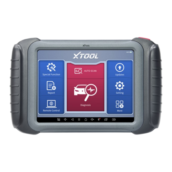
FRONT VIEW OF TABLET Figure 1-1 Sample of Tablet Front View The front of the main unit is a touchable display screen, you can use your fingers to operate on the screen to complete the car diagnosis. -
Page 10: Back View Of Tablet
BACK VIEW OF TABLET ④ ① ② ③ Figure 1-2 Sample of Tablet Back View ① Camera: 8-megapixel camera, for taking pictures. ② Tablet Holder: Used to support the tablet, flexible adjustment of the tablet height as needed. ③ Nameplate: Display the basic information about the tablet such as product name and model etc. -
Page 11: Host Ports
① Fig 1-3 Sample of Tablet Host Ports ① USB 3.0 port: Data transfer port. (*Please do not use other non- xtool UBS cable with this port!) ② VGA port: A reserved interface can be used for charging. ③ DC charging port: Charging port, connected to the charger can be charged. -
Page 12: Packing List
⚫ Connectivity ⚫ Wi-Fi 8-megapixel autofocus rear camera with Camera flash Sensor Gravity sensor Audio Input/ Audio Output Microphone/ Loudspeaker ⚫ USB3.0 ⚫ Ports DC charging port ⚫ VGA port Battery 10000mAh 3.7V lithium polymer battery Input Voltage 12V DC Operating Temperature -10~50℃... -
Page 13: Getting Started
Tool kit Certificate of Quality Accessories Packing List User Manual Carton 2. G ETTING TARTED 2.1. ACTIVATION After first-time users press and hold the power button to turn on the system, the system will automatically enter the guide process and request to select the language for the operating system. - Page 14 Figure 2-2 Sample of Activation (Screen 1) Click Start Activate to enter the activation page, as shown below: Figure 2-3 Sample of Activation (Screen 2) A pop-up window showing Activation Success indicates that you have completed the first boot setup, click OK to enter the diagnostic system and start using the device.
-
Page 15: Main Interface
Figure 2-4 Sample of Activation (Screen 3) 2.2. MAIN INTERFACE OPERATION SYSTEM As shown in the figure below, this interface is the main page of the operating system of the device. You can also return to this interface at any time by clicking home button on the bottom navigation bar. - Page 16 H6 ELITE Smart Diagnostics System Browser: Click on the browser icon to enter the browser to view the official website of Xtool or search for other information. Gallery: Click the Gallery icon to enter the album to quickly view the pictures or screenshots stored in the device. You can select the...
-
Page 17: Diagnosis System Entrance
Figure 2-6 Sample of ES File Explorer H6 ELITE Smart Diagnostics System: The App allows you to diagnose your vehicle and offers a range of specialist maintenance services. DIAGNOSIS SYSTEM ENTRANCE Once activated, you will automatically enter the diagnostic system with the following main screen. -
Page 18: Function Buttons
Figure 2-7 Sample of APP Main Page The main interface is mainly composed of Function Buttons and Navigation Buttons. The touch screen navigation is menu-driven, and you can quickly access functions by clicking on the option title and answering the dialogue window. -
Page 19: Navigation Buttons
You can view the vehicle diagnostic report In case of failure, you can control the diagnostic equipment remotely Users can upgrade the upgradeable software with one click Users can set the language, unit, workshop information here Users can view extended functions, such as endoscope NAVIGATION BUTTONS Instructions for operating the navigation bar buttons at the bottom of the... -
Page 20: Notification Bar
Click this button to return to the diagnostic vehicle interface Press for screen recording NOTIFICATION BAR Slide down to open the notification bar. Users can adjust the brightness of the screen when they need it, and you can also connect Wi-Fi and so on. Figure 2-8 Sample of NOTIFICATION BAR... -
Page 21: Update &Delete Software
3. U &D PDATE ELETE OFTWARE 3.1. UPDATE SOFTWARE After activating the device, please update the software in "Update" first. To access the update application, open the diagnosis application and click UPDATE, shown as below: Figure 3-1 Sample of Update List Click the magnifying glass in the upper right corner to search for model ⚫... -
Page 22: Delete Software
3.2. DELETE SOFTWARE Long-press the unwanted software until it has been selected, then click the Delete button shown on the upper part of the screen. And you can select and delete multiple software at once. Figure 3-2 Sample of How to Delete Vehicle Software ** When the device prompts that the memory is insufficient, you can delete the models that are not frequently used to release the memory. -
Page 23: Diagnosis
(SRS), and perform kinds of actuation tests. 4.1. VEHICLE CONNECTION The diagnosis operation needs to connect the H6 Elite Smart Diagnostics System to a vehicle first so that the tablet can establish correct vehicle communication. Please perform the following steps: Since the display tablet and the VCI box are integrated, to communicate with the vehicle, the OBDⅡ-16 connector must be connected to the main test... - Page 24 Figure 4-1 Sample of How to Connect Device to Vehicle ① Tablet ② Main Test Cable ③ OBDII-16 Connector ④ Vehicle ⚫ Precautions for Diagnosis 1. The battery voltage range on the car: +9~+36V DC; 2. When testing some special functions, the operator must operate according to the prompts and meet the test conditions.
-
Page 25: Diagnosis
H6 Elite diagnostic function, please upgrade the vehicle diagnostic software to the latest version or consult the technical service department; 5. It is forbidden to use wiring harnesses other than Xtool for connection testing to avoid unnecessary losses; 6. In the communication between the H6 ELITE Smart Diagnostics System and the vehicle, it is forbidden to shut down directly. - Page 26 Click the VIN button in the upper left corner, you can choose to enter the vehicle diagnosis through the 2 ways of AUTO SCAN/MANUAL ENTER. ⚫ AUTO SCAN: It supports automatic reading of vehicle VIN code. You also can tap on the button “AUTO SCAN” on the diagnosis system entrance to use this function.
- Page 27 Figure 4-4 Sample of Vehicle Selection by Ares OBD- Ⅱ supports reading the related fault codes of PCM; DEMO, a demonstration program; Click this button to experience and learn the operation process of the diagnostic function. Some models provide multiple entry methods in the sub-menu, including: ⚫...
-
Page 28: Diagnosis Functions
Enter "System Selection", you can also diagnose the vehicle according to the system according to your needs after selecting the model. DIAGNOSIS FUNCTIONS Diagnostics functions supported by H6 Elite Smart Diagnostics System are as below: Read ECU Information ⚫... - Page 29 systems, all mean to read ECU related software and hardware versions, models and production date of diesel engine, part number, etc. It is convenient for us to make a record in the maintenance process, and it also makes data feedback and management easier. Figure 4-8 Sample of ECU Information Read Trouble Code ◼...
- Page 30 *Tip: In the process of diagnosis, if the device shows “System is OK” or “No Trouble Code”, it means there is no related trouble code stored in ECU or some troubles are not under the control of ECU, most of these troubles are mechanical system troubles or executive circuit troubles, it is also possible that signal of the sensor may bias within limits, which can be judged in Live Data.
- Page 31 That is to read the parameters of the running engine, such as oil pressure, temperature, engine speed, fuel oil temperature, coolant temperature, intake air temperature, etc. Based on these parameters, we can judge directly where the problem lies, which helps to narrow the scope of maintenance. For some vehicles, during their actual operation, the problems such as performance characteristics offset, sensitivity reduction, can be judged in live data.
- Page 32 Figure 4-12 Sample of the PIDs List related by Key Words ⚫ Custom Support to show the selected PIDs. Figure 4-13 Sample of Custom the PIDs Click Display All, back to the page which display all PIDs...
- Page 33 Combine ⚫ Support to select multiple PIDs and click 【Combine】 to make different graphs into one chart. *Note: When combining the PIDs, the number of them selected at a time should not exceed 5 Figure 4-14 Sample of the PIDs Combination ⚫...
- Page 34 The living data items supported by vehicles of different brands are not the same, so the freeze frames displayed when diagnosing vehicles of different brands may also be different. Some vehicles may not have the option of a freeze-frame which means that the model does not support this function. Take Renault Duster ii ph as an example, after selecting the system to enter the lower freeze frame menu, the device will list all the fault codes under the system.
- Page 35 Context when fault appeared: record the live data when fault appeared to help the user to know the vehicle status. *Some vehicles don't support this function; users will get a prompt when they click the menu. Current context: Displays the current live data stream associated with the Figure 4-19 Sample of the Freeze frame for Renault Duster ii ph (Screen 3) dditional data: record other data related to the fault...
- Page 36 Figure 4-20 Sample of the Freeze frame for Renault Duster ii ph (Screen 4) ◼ Special functions Figure 4-21 Sample of the Special Functions for the Injection system of Renault Duster ii Usually, special functions provide various reset or re-learning functions menus for most vehicle systems.
-
Page 37: Special Functions
5. S PECIAL UNCTIONS The H6 ELITE Smart Diagnostics System supports the commonly used special reset functions, allowing you to quickly access your vehicle system for various scheduled services, maintenance and reset performance, eliminating the need to reset after resolving common problems. This user manual lists some of the commonly used special reset services for your reference. - Page 38 This function can be performed in the following cases: If the service lamp is on, you must provide service for the car. After ⚫ service, you need to reset the driving mileage or driving time so that the service lamp turns off and the system enables the new service cycle. ⚫...
-
Page 39: Epb
Figure 5-3 Sample of oil reset function (screen 2) 5.2 EPB Electronic Parking Brake (EPB) System reset is a popular special function. You can use this function to reset the electronic parking brake system and brake pads, which also supports the brake pad replacement (retraction, release of the brake pump), G-sensor, and body angle calibration. - Page 40 Enter the EPB menu and choose relevant models according to the vehicle being tested. Follow the instructions displayed and press YES after completing the instructions shown. Figure 5-4 Sample of EPB function (screen 1) Enter the Enter maintenance mode menu and release the handbrake brake.
-
Page 41: Sas
Wait until the message of ‘Successful operation’ popes up. And press OK to exit the menu. Enter the Exit maintenance mode menu and wait until the message of ‘‘Successful operation’ popes up. 5.3 SAS Steering Angle Sensors (SAS) System Calibration permanently stores the current steering wheel position as the straight-ahead position in the SAS EEPROM. - Page 42 Figure 5-6 Sample of SAS function (screen 1) Wait until the following instruction is displayed and press Yes after completing the instructions shown. Figure 5-7 Sample of SAS function (screen 2) Follow the instructions displayed and press OK after completing the instructions shown.
- Page 43 Figure 5-8 Sample of SAS function (screen 3) Wait until the following instruction is displayed and press OK after completing the instructions shown. Figure 5-9 Sample of SAS function (screen 4) Message of ‘Function execution is completed’ displayed when SAS function has successfully performed.
-
Page 44: Dpf
5.4 DPF The Diesel Particle Filter (DPF) function manages DPF regeneration, DPF component replacement teach-in, and DPF teach-in after replacing the engine control module (ECM). The ECM monitors driving style and selects a suitable time to employ regeneration. Vehicles driven a lot at idling speed and low load will attempt to regenerate earlier than vehicles driven more with higher load and speed. - Page 45 Figure 5-10 Sample of DPF function (screen 1) Read the fuel tank level and make sure that it fulfills the requirement displayed. Read the carbon deposit load. Choose the drive to warm up and follow the instructions listed below. And press OK after completing the instructions shown. Figure 5-11 Sample of DPF function (screen 2) Read the note carefully and follow the instructions shown on the...
- Page 46 screen. And press OK after completing the instructions shown. Figure 5-12 Sample of DPF function (screen 3) Follow the instructions displayed and press OK after completing the instructions shown. Please pay attention to the Note. Figure 5-13 Sample of DPF function (screen 4) Press the OK button to start the regeneration.
- Page 47 Figure 5-14 Sample of DPF function (screen 5) 10. Wait for the value of carbon deposit to decrease until a message of ‘Emergency regeneration has been completed’ popes up, this process may take up to 40 minutes. Figure 5-15 Sample of DPF function (screen 5) 11.
-
Page 48: Bms Reset
Figure 5-16 Sample of DPF function (screen 6) 12. Press drop out to exit the DPF function. 5.5 BMS RESET The Battery Management System (BMS) allows the scan tool to evaluate the battery charge state, monitor the close-circuit current, register the battery replacement, and activate the rest state of the vehicle. - Page 49 The operation guidelines of the BMS Reset function are shown as below: Enter the BMS Reset menu and choose relevant models according to the vehicle being tested. Turn on the ignition switch. Press OK to continue the BMS function. Enter battery capacity (within the given range) and press OK after the input.
-
Page 50: Throttle
Enter the 10-digit battery serial number and press OK after the input. Figure 5-19 Sample of BMS function (screen 3) 5.6 THROTTLE Throttle Position Sensor (TPS) Match, this function enables you to make initial settings to throttle actuators and returns the “learned” values stored on ECU to the default state. - Page 51 Figure 5-20 Sample of throttle function (screen 1) Wait until all the parameters are read and displayed. Figure 5-21 Sample of throttle function (screen 2) Press the F2 button and wait until a message of ‘Match successfully’ pops up.
-
Page 52: Injector Coding
5.7 INJECTOR CODING This function can write the identification code of the fuel injector into the ECU so that the ECU can recognize and work normally. Write actual injector code or rewrite code in the ECU to the injector code of the corresponding cylinder for controlling accurately and correcting cylinder injection quantity. - Page 53 Figure 5-22 Sample of injector coding function (screen 1) Read and confirm the value stored in the cylinders. Figure 5-23 Sample of injector coding function (screen 2) Enter the Change the value of cylinder menu of the replaced injector(s), enter the new 5-digit value, and then press OK.
- Page 54 Figure 5-24 Sample of injector coding function (screen 3) Wait until the message ‘Write successfully’ pops up. Turn off the ignition switch. Wait until the message asked you to turn on the ignition switch. Re-enter the Fuel injection nozzle injection volume adjustment menu to check whether the new value(s) are shown.
-
Page 55: Gearbox Match
5.8 GEARBOX MATCH After changing the gearbox or changing the gearbox ECU, you need to use the gearbox matching function to re-match the engine and the gearbox. Before resetting the gearbox, please check the gearbox control unit to ensure that there is no fault code. If there is a fault code, the gearbox memory function cannot be reset. - Page 56 learning is not performed for a car equipped with a Delphi engine, the MIL turns on after the engine is started. The diagnostic device detects the DTC P1336 'Gear not learned'. In this case, you must use the diagnostic device to perform gear learning for the car.
-
Page 57: Report
Figure 5-28 Sample of gear learning function (screen 2) Press the accelerator pedal down and hold it until a message of ‘The learning is successful, please release the accelerator pedal.’ pops up. Release the accelerator pedal and press OK to exit the gear learning function. -
Page 58: Report
Figure 6-1 Sample of Report 6.1. REPORT This feature provides a history of diagnostic reports, where you can view and delete the vehicle's diagnostic reports according to your needs. Figure 6-2 Sample of Report List When you open the report, located in the header of the table is the studio information you filled in advance in the system setup, then the information of the vehicle, including the diagnosis date and time, VIN, vehicle brand, diagnosis path, etc., as shown as below:... - Page 59 Print PDF Report ◼ As you can see, you also could click " Print PDF Report " at the bottom right corner to output the pdf report. If you need to close the report, you could tap on the button “Exit”. Please follow the below steps to print your report▼...
-
Page 60: Replay
6.2. REPLAY This function allows you to replay the living data recorded during the diagnosis process. Figure 6-6 Sample of Data Playback, Screen 1 Before replaying the living data, please make sure you click on the "Save to Reference" button during the diagnosis Figure 6-7 Sample of Data Playback, Screen 2 6.3. -
Page 61: Settings
7. S ETTINGS Figure 7-1 Sample of Settings Click the Settings button to adjust the default settings and view information about the H6 ELITE Smart Diagnostics System. There are seven options available in the system settings: Language ⚫ Units ⚫... - Page 62 Figure 7-2 Sample of Language Selection Users can switch between English and local official languages on the device by themselves. If you need to switch other languages, please contact the dealer to unbind the current language configuration and rebind it to the language configuration you need to switch.
-
Page 63: Units
UNITS 7.2. You can switch the unit used by the system. H6 ELITE Smart Diagnostics System provides you with metric and imperial units. You can directly click on the unit when you need it, after the switch is successful, a blue checkmark will be shown behind the unit’s name. -
Page 64: Firmware Information
Figure 7-5 Sample of Workshop Information 7.4. FIRMWARE INFORMATION You can view the firmware information here, including the firmware name, the latest firmware version, the currently used firmware version, and the firmware type. Figure 7-6 Sample of Firmware Information NOTE: To view the firmware information, you need to enter the diagnostic package first to get it works. -
Page 65: Factory Reset
8. F ACTORY ESET After first-time users turn on the system, the system will automatically enter the guide process and request the user to select the system operating language. Figure 8-1 Sample of Selecting Languages After selecting the system language, click Next to enter the Wi-Fi connection page, as shown below: Figure 8-2 Sample of Selecting Wi-Fi... - Page 66 Select a network to connect to on the Wi-Fi connection page. After successful network connection, the automatic system will jump to Factory mode to download the software: Figure 8-3 Sample of Factory Mode Once the software has been downloaded, the tablet will automatically reboot and request the system language selection again.
- Page 67 After setting the system language, you will enter the activation page, as shown in the figure below. You can also click the "Trial" button in the upper right corner to try it out before activation. Figure 8-5 Sample of Activation, Screen 1 Click Start Activate to enter the activation page, as shown below: Figure 8-6 Sample of Activation, Screen 2 A pop-up window showing Activation Success indicates that you have...
-
Page 68: Remote Assistance
If you encounter problems and are not able to solve them, you could open this application and ask for remote assistance. To obtain remote support from your partners or Xtool After-service Center: 1. Turn on the power of the tablet. - Page 69 (http://www.teamviewer.com) online, and then start the software on his/her tablet at the same time, to provide support and remote control of the tablet. 4. Provide your ID to the partner or Xtool technician, and then wait for him/her to send you a remote-control request.
-
Page 70: Faq
10. FAQ Q1: FAILED TO GENERATE DIAGNOSIS REPORT 1. Currently only perform diagnostic functions, that is, read ECU information, read code and clear code, live data, freeze frame, which can trigger a diagnostic report. Other functions, such as immobilization and maintenance services will not be displayed in the report. -
Page 71: Q2: How To Print Diagnosis Report
Fig 9-3 Sample1: How to clear APP cache Q2: HOW TO PRINT DIAGNOSIS REPORT The XTOOL device is compatible with third-party print drivers. You can download the printer driver you need in the browser that comes with the tablet to install it, and then set your printer in the OS settings. After the setting... -
Page 72: Q3: Failed To Extract Files
Q3: FAILED TO EXTRACT FILES Since the XTOOL tablet is equipped with an Android system, you have to confirm the system type of receiver. For Android: supports transferring files via Bluetooth, USB cable, etc.; For IOS: only supports transferring files through a wired connection (Bluetooth connection is not available). -
Page 73: Q8: Failed To Diagnose Vehicle
2. Settings->Language->Choose language 3. Back to Updates to update all the software again Q8: FAILED TO DIAGNOSE VEHICLE 1. Contact your dealer to confirm whether the vehicle model is supported by the scan tool you owned. 2. Check whether the vehicle is properly connected (e.g. whether the ignition is ON, and the diagnosis of some vehicles need to turn on the engine), If your tablet is equipped with a VCI box, please check the status of the VCI box indicator. -
Page 74: Q10: Failed To Turn On When Charging
Q10: FAILED TO TURN ON WHEN CHARGING In the charging state, you need to first press the power button to light up the screen (showing the charging status). Then press and hold the power button for 4-5 seconds until the boot animation is shown on screen. Q11: FAILED TO OPEN THE DIAGNOSIS APP “With PROMPT ‘Sync your device. -
Page 75: Warranty & Services
ERVICES Shenzhen Xtooltech Intelligent Co., LTD.(the Company) warrants to the original retail purchaser of this XTOOL device that should this product or any part thereof during normal usage and under normal conditions be proven defective in material or workmanship that results in product failure within one year from the date of purchase, such defect(s) will be repaired, or replaced (with new or rebuilt parts) with Proof of Purchase, at the Company’s option,... - Page 76 4.Damage resulting from connection to, or use of any accessory or other product not approved or authorized by the Company; 5.Defects in appearance, cosmetic, decorative, or structural items such as framing and non-operating parts; 6.Products damaged from external causes such as fire, dirt, sand, battery leakage, blown fuse, theft, or improper usage of any electrical source.
-
Page 77: Shenzhen Xtooltech Intelligent Co., Ltd
., L HENZHEN TOOLTECH NTELLIGENT Company address: 17&18/F, Building A2, Creativity City, Liuxian Avenue, Nanshan District, Shenzhen, China Factory address: 2/F, Building 12, Tangtou Third Industrial Zone, Shiyan Street, Baoan District, Shenzhen, China Service-Hotline: 0086-755-21670995/86267858 Email: marketing@Xtooltech.com Fax: 0755-83461644 Website: www.Xtooltech.com...
Need help?
Do you have a question about the H6 Elite Smart and is the answer not in the manual?
Questions and answers