
Related Manuals for Vidicode APRESA Series


Summary of Contents for Vidicode APRESA Series
- Page 1 Call Recorder APRESA & Call Recorder APRESA Compact Installation Manual V 2.20 (VC1988)
- Page 2 APRESA. LICENSES Store your APRESA licenses in a safe place as you may need these in the future. € THIS EQUIPMENT MUST BE EARTHED FOR SAFETY REASONS INSTALLATION MANUAL APRESA COPYRIGHT © 2011-2017 VIDICODE ®...
- Page 3 This manual was written to support and guide customers in the installation process of the hardware and software of the: APRESA STANDARD 4U SERVER APRESA SUPER MICRO 1U SERVER APRESA SUPER MICRO 4U SERVER APRESA COMPACT APRESA SOFTWARE ONLY All products of VIDICODE INSTALLATION MANUAL APRESA COPYRIGHT © 2011-2017 VIDICODE ®...
- Page 4 How to use this manual. You may want to install a complete “VIDICODE made” APRESA server while others want to install the APRESA software-only on their alternative hardware. Also, the expansion of existing APRESA systems may need some guidance. Expanding an APRESA system involves adding recording channels, increasing storage capacity or adding/ changing a RAID volume.
-
Page 5: Table Of Contents
ROAD MAP ................................8 INSTALLATION START ............................ 9 1.1............................9 ITUATIONS 1.1.1. The “made by VIDICODE” APRESA Server / APRESA Compact.............. 9 1.1.2. Software only ............................9 1.1.3. Upgrading an existing APRESA ......................9 1.2.................. 10 ACKAGE CONTENTS... - Page 6 RAID ..................72 UILDING OR CHANGING A SOFTWARE VOLUME BACKUP AND RESTORE BACKUP ......................... 73 MAINTENANCE .............................. 74 APPLICABLE VIDICODE ARTICLE CODES FOR APRESA ................75 REDUNDANT POWER SUPLLY ........................77 STORAGE OPTIONS ............................79 11.1........................... 79 ONFIGURATION 11.2.
- Page 7 +/2.0 ..................86 12.3. DTP-X0C/PCI+ / DTP-X0C/PCI + ....................87 GNU GENERAL PUBLIC LICENSE...................... 88 TERMINILOGY EXPLAINED ........................ 89 COPYRIGHT AND TRADEMARKS ...................... 92 FCC STATEMENT ............................ 92 ROHS 2 STATEMENT ..........................92 INSTALLATION MANUAL APRESA COPYRIGHT © 2011-2017 VIDICODE ®...
-
Page 8: Road Map
I/F C AR D S ETTIN G S F U LL E TC D ETAILS TE LE C O M W IR IN G C O M M IS SIO N IN G D W G 1129_1 EN D INSTALLATION MANUAL APRESA COPYRIGHT © 2011-2017 VIDICODE ®... -
Page 9: Installation Start
You will find the APRESA software already installed and running on the product. Channel licenses are activated and interface cards will be installed according to your purchase order by VIDICODE. You are advised to read the introduction and the go directly to the mounting, software configuration, telecom wiring, and commissioning sections. -
Page 10: Package Contents, Materials And Tooling
Open the package carefully, and make sure that none of the items that are listed below are missing This product has a very high level of flexibility and inherently there is no standard package content. To help you in checking the delivery read the following: Package = “VIDICODE APRESA server” APRESA SERVER S&U LICENSE Support &... -
Page 11: Advised Materials
RJ48C to BNC adapter Coaxial T-Splitter(s) 1.2.3. Advised tooling We advise you to check the following list of tooling of before you start installing the system: Standard installers tooling kit; RJ modular connector crimp tool INSTALLATION MANUAL APRESA COPYRIGHT © 2011-2017 VIDICODE ®... -
Page 12: Introduction To The Apresa Server
(e.g. identical between different APRESA units). The sole purpose of the DVD is to accommodate software installation. Because the software is pre- installed by VIDICODE, the DVD has no immediate function. The DVD is used when software must be re-installed in the future for whatever reason. -
Page 13: The Black 19" Housing
HARD DISC BUTTON ACTIVITY LED NUM LOCK BUTTON NUM LOCK LED (NOT USED) (NOT USED) RE S E T P OW E R H.D.D KB-LK KB-LK POW ER DWG1131_0 DOOR (OPENED) SW ITCH INSTALLATION MANUAL APRESA COPYRIGHT © 2011-2017 VIDICODE ®... -
Page 14: Back Side, C2Sbc-Q Motherboard, Standard Psu
• This housing also accommodates the X9-SCM motherboard. Refer to the next section for information. • The PSU alarm mute button location may be located elsewhere on your unit. Specifications of the “BLACK” APRESA server INSTALLATION MANUAL APRESA COPYRIGHT © 2011-2017 VIDICODE ®... -
Page 15: Enclosure
500W Optional (for all specifications: www.supermicro.com) Optional: 1+1 redundant power supply : 4 slots PCI-e : 2 slots 2.1.3. Hard drive (various configurations possible) INTERFACE : SATA 3GBIT/SEC SIZE : 3.5 INCH INSTALLATION MANUAL APRESA COPYRIGHT © 2011-2017 VIDICODE ®... -
Page 16: Dvd R/W
: +10….+35 °C (Operating) or - 10 - + 65 °C (Storage) HUMIDITY : 8%-90% No condensing, operating and storage. 2.1.8. Approvals EMC APPROVAL : EN55022 / EN55024 / FCC15 SAFETY : EN60950 INSTALLATION MANUAL APRESA COPYRIGHT © 2011-2017 VIDICODE ®... -
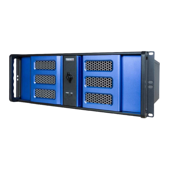
Page 17: The Blue 19" Housing
HARD DRIVE DWG1171_00 ACT IVIT Y LED Front side, door opened VENT ILAT ION HOLES OPENED DOOR OPT IONAL SAT A BAY EJECT VIDICODE APRESA POWER HDD RESET ON/OFF DWG1172_00 USB (NOT USED) INSTALLATION MANUAL APRESA COPYRIGHT © 2011-2017 VIDICODE ®... -
Page 18: Back Side, X9-Scm Motherboard. (Obsolte)
Back side, X10-SLL motherboard. MAINS POWER SWITCH POWER INTERFACE CARDS (NOT ON ALL MODELS) ENTRY SLOTS DISPLAY (NOT USED DWG1186_00 SERIAL RS232 IPMI VOIP ETHERNET (NOT USED) 4XUSB2.0 PC ETHERNET (NOT USED) INSTALLATION MANUAL APRESA COPYRIGHT © 2011-2017 VIDICODE ®... -
Page 19: Pecifications Of The "Blue" Apresa Server
SIZE : 3.5 INCH : 7200 CACHE : 16MByte QUALITY GRADE : 24/7 CAPACITY : 1T BYTE (standard configuration) Optional 1or 2 TBYTE RAID VOLUMES : Optional, Software RAID1 or Software RAID5 INSTALLATION MANUAL APRESA COPYRIGHT © 2011-2017 VIDICODE ®... -
Page 20: Dvd R/W
: +10 …. +35 °C (Operating) or - 10 …. + 65 °C (Storage) HUMIDITY : 8%-90% No condensing, operating and storage. 2.3.8. Approvals EMC APPROVAL : EN55022 / EN55024 / FCC15 SAFETY : EN60950 INSTALLATION MANUAL APRESA COPYRIGHT © 2011-2017 VIDICODE ®... -
Page 21: The Apresa-Compact
DWG1175_00 Front side, door opened VoIP| ISD N| TDM | POTS| AUD IO APRESA Co m p act - Li n e DWG117 6_ 00 AUDIO OPEN DOOR (NOT USED) Back side INSTALLATION MANUAL APRESA COPYRIGHT © 2011-2017 VIDICODE ®... - Page 22 • The “APRESA-Compact IP5” and the “APRESA-Compact IP10” with a network port option (VIDICODE art .no 010.05570) installed (in the expansion slot) interfaces to the VoIP over LAN port marked ‘Ethernet’ in the figure above. The normal LAN traffic is connected to the LAN card in the expansion slot.
-
Page 23: Specifications Of The Apresa-Compact Server
CAPACITY : 1TBYTE 2.5.4. Supported PCIe interface cards ANALOG : SYNWAY TYPE ATP- 24A/PCIe+/2.0 : 8CH max. SYNWAY TYPE ATP- 24A/PCIe+/3.0 : 8CH max. : SYNWAY TYPE DST- 24B/PCIe+/2.0 : 8CH max. INSTALLATION MANUAL APRESA COPYRIGHT © 2011-2017 VIDICODE ®... -
Page 24: Environmental Specification
: +10 - +35 °C (Operating) or - 10 - + 65 °C (Storage) HUMIDITY : 8%-90% No condensing, operating and storage. 2.5.6. Approvals EMC APPROVAL : EN55022 / EN55024 / FCC15 SAFETY : EN60950 INSTALLATION MANUAL APRESA COPYRIGHT © 2011-2017 VIDICODE ®... -
Page 25: Apresa Base Software
- APRESA license, Channel license, G.729 license etc. - WORK-PC (for processing the licenses / WEB configuration APRESA) - Interface cards as applicable. If you have purchased the complete “VIDICODE made” INST ALLAT ION ST ART APRESA server can skip this chapter. Your product will... -
Page 26: Hardware Requirements
Open the chassis by removing the 2 screws of the top cover plate to gain excess to the PCI(PCIe) expansion slots. (only for VIDICODE, other vendor hardware may be opened differently, refer to the documentation supplied by your typical hardware vendor) Locate a free PCI or PCI-e slot to accommodate the interface card you want to install. -
Page 27: Software Installation Procedure From The Cd
When installing the software RAID 1 or software RAIID 5 version of APRESA you must set the BIOS-setting for RAID to NO RAID ( RAID is handled by software ) Select : “SAVE & EXIT” (enter : & 3.3.3. Prepare an installation CD INSTALLATION MANUAL APRESA COPYRIGHT © 2011-2017 VIDICODE ®... -
Page 28: Installation From Cd
The APRESA quick guide lists the internet link to the APRESA-ISO image that will be ‘burned’ to CD in order to become the APRESA Base Software installation CD. Ask VIDICODE sales for a “APRESA quick guide” if you don’t have one at hand. One single image supports all the different hard drive configurations (NORAID/RAID0/RAID5) and the versions with the encryption feature. - Page 29 - As Subnet mask, fill in: 255.255.255.0 B. If the PC was already set to a static IP address, but in another subnet, then it is possible to add an extra IP address to the PC configuration. INSTALLATION MANUAL APRESA COPYRIGHT © 2011-2017 VIDICODE ®...
- Page 30 • Click Apply and let the network restart If after the restart, the new IP address of the Apresa is not known for some reason, the program Apresa IP Lookup can be used. INSTALLATION MANUAL APRESA COPYRIGHT © 2011-2017 VIDICODE ®...
- Page 31 If this program cannot find the IP address, then the current IP address of the Apresa will be displayed on the monitor. After this is completed, the network configuration adjustment for the PC that was discussed can be reversed. INSTALLATION MANUAL APRESA COPYRIGHT © 2011-2017 VIDICODE ®...
-
Page 32: Apresa Base Software License Activation
ENT ER 'COMPANY NAME' AND PRESS OK APRESA LICENSED COMPLET ED DWG1158_00 NOTE : If you can’t “click” on the APRESA web page to reach the VIDICODE license server go to : http://www.vidicode.com/activation INSTALLATION MANUAL APRESA COPYRIGHT © 2011-2017 VIDICODE ®... - Page 33 T h en cl i ck on th i s NOT l i cen se d yet l i nk DWG1 16 0_ 00 On the screen below, enter the license key and press ok INSTALLATION MANUAL APRESA COPYRIGHT © 2011-2017 VIDICODE ®...
- Page 34 DWG1 16 3_ 00 By clicking the link you will be connected to the VIDICODE license server WEB page. INSTALLATION MANUAL APRESA COPYRIGHT © 2011-2017 VIDICODE ®...
- Page 35 Enter COM PANY nam e PAST E the code CT RL+V PRESS Subm it DWG1164_00 On the screen below copy the activation code (select then CTRL+C) COPY the co de CT RL+C DWG11 65_00 INSTALLATION MANUAL APRESA COPYRIGHT © 2011-2017 VIDICODE ®...
- Page 36 If the software serial number a realistic value (not 0 but a number larger then 80000) then the license is activated. Note that you need the software serial number to install recording channels on your APRESA. See the section “channel license activation”. INSTALLATION MANUAL APRESA COPYRIGHT © 2011-2017 VIDICODE ®...
-
Page 37: Base Software Update
Or… 4-B. When Apresa has no internet connection, download the update file from http://www.vidicode.com/softwupd/apresa-update.tgz to your PC. In the Apresa web interface, select this file on your PC, and click Upload. After the file uploaded, or after Apresa has downloaded the update itself, Apresa displays that it is updating the system. -
Page 38: Channel License Activation
AP RE SA CHA NNEL LICENSING COM PL ET ED DWG1159 _00 NOTE : If you can’t “click” on the APRESA web page to reach the VIDICODE license server go to : http://www.vidicode.com/channels INSTALLATION MANUAL APRESA COPYRIGHT © 2011-2017 VIDICODE ®... - Page 39 (CTRL+C) the “Software serial number” that is displayed; • Click Options -> System settings > Activate new channel license. This will open the VIDICODE channel license server on the internet; • Enter the license key of the channel license (including the dashes);...
-
Page 40: Codec License Activation (Optional)
(CTRL+C) the “Software serial number” that is displayed; • Click Options -> System settings > Activate new channel license. This will open the VIDICODE channel license server on the internet; • Enter the license key of the codec license (including the dashes);... -
Page 41: Mounting
4. MOUNTING This chapter describes the mounting of the “made by VIDICODE” version of the APRESA server. If you use another brand of server then things may be different in your situation. A full APRESA installation involves the following steps: •... -
Page 42: Mounting Apresa Into A 19 Inch Cabinet
A simple way to comply is using the third pin on the APRESA-PSU power inlet. Using a good quality standard (earthed) mains cable and insert it to an EARTHED mains source. Absent or improper grounding may cause instability in operation as well as unsafe situations. INSTALLATION MANUAL APRESA COPYRIGHT © 2011-2017 VIDICODE ®... -
Page 43: Telecom Wiring
A special chapter is dedicated to the specification of the interface cards. For TETRA and VOIP recording NO special interface card is needed. These networks are Ethernet based and both use the designated Ethernet port located on the PC motherboard. WIRING INSTALLATION MANUAL APRESA COPYRIGHT © 2011-2017 VIDICODE ®... - Page 44 RTP packets to the APRESA VoIP Ethernet port. RJ11 PATCHBOX -Indicates the compatibility with the simple 24 channel RJ11 patch panel. TAPPING PATCHBOX -Indicates the compatibility with the splitting 24 channel Tapping Patch box. INSTALLATION MANUAL APRESA COPYRIGHT © 2011-2017 VIDICODE ®...
-
Page 45: Connector Locations
APRESA monitors the communication line to be recorded electrically “in parallel”. As a result, we will have to make “T” junctions. For the RJ-modular connection system one can use readily on the market available “T” splitters (RJ12 or RJ45) INSTALLATION MANUAL APRESA COPYRIGHT © 2011-2017 VIDICODE ®... -
Page 46: Wiring Audio Taps
(typically an amplifier) you probably want to add a line terminator in some situations. If you want, f.i. 600 ohms line termination you have to provide the 600 ohm termination resistor externally. LINE term ination AUDIO AUDIO CHx-A SOURCE SOURCE APRESA CHx-B BALANCED PAIR DWG1136_00 INSTALLATION MANUAL APRESA COPYRIGHT © 2011-2017 VIDICODE ®... -
Page 47: Un-Balance Signals
AUDIO CHx-A SOURCE SOURCE APRESA CHx-B SINGLE ENDED When dealing with an unbalanced signal we advise only to use the best quality of shielded cable that is kept as short as possible. INSTALLATION MANUAL APRESA COPYRIGHT © 2011-2017 VIDICODE ®... -
Page 48: Wiring Using The Rj11 Patch Box
25 colored twisted pairs. Only 24 twisted pairs represent the recording channels, the 25 twisted pair has no function and can be ignored. INSTALLATION MANUAL APRESA COPYRIGHT © 2011-2017 VIDICODE ®... - Page 49 BRACKET) AND THE NUMBERS 1/26 AND 25/50 ARE SWAPPED IN COMPAPRISON WITH THE NUMBERING PRINTED ON THE CONNECTOR BY THE CONNECTOR MANUFACTURER. WE USE THE SWAPPED NUMBERING TO KEEP COMPLIANCE WITH DOCUMENTATION OF THE INTERFACE CARD MANUFACTURER. INSTALLATION MANUAL APRESA COPYRIGHT © 2011-2017 VIDICODE ®...
-
Page 50: Wiring Analog Telephony (Pots) Taps
1. Direct wiring of the RJ21 connector of the interface card (pinning see above) 2. With the RJ11 patch box (POTS signal to pins 3&4,NO CONNECTION TO OTHER PINS ! 3. With the RJ45 Tapping Patch box. INSTALLATION MANUAL APRESA COPYRIGHT © 2011-2017 VIDICODE ®... -
Page 51: Wiring Tdm Telephony Taps
The TDM wiring taps can be realized in 3 ways: 1. Direct wiring of the RJ21 connector of the interface card (pinning see above) 2. With the RJ11 patch box 3. With the RJ45 patch box INSTALLATION MANUAL APRESA COPYRIGHT © 2011-2017 VIDICODE ®... - Page 52 24 C H R J11 to R J21 PATC H BO X Always test ONE custom cable first to R J21/R J21 cable avoid time and material loss. TO APR ESA D W G 1141_01 INSTALLATION MANUAL APRESA COPYRIGHT © 2011-2017 VIDICODE ®...
- Page 53 IMPORTANT NOTES ON USING THE RJ11 PATCH BOX WITH -WIRE CONNECTION YOU CAN USE OUTLETS OF THE RJ11 PATCH BOX ONLY WITH -WIRE CONNECTION YOU CAN USE THE NUMBERED OUTLETS OF THE RJ11 PATCH BOX INSTALLATION MANUAL APRESA COPYRIGHT © 2011-2017 VIDICODE ®...
-
Page 54: Wiring Isdn2 Telephony Taps (Basic Rate Isdn)
Further information can be found in the chapter that describes the Tapping Patchbox. 5.7. Wiring ISDN2 Telephony TAPS (Basic rate ISDN) ISDN2 or ISDN-basic rate is from a wiring point of view pretty much identical the 4-wire TDM installation. Refer to the previous chapter. INSTALLATION MANUAL APRESA COPYRIGHT © 2011-2017 VIDICODE ®... -
Page 55: Wiring Isdn E1/T1 Telephony Taps
Too much framing errors will occur and the APRESA stops recording this specific trunk. (Restart recording component to recover from this situation) INSTALLATION MANUAL APRESA COPYRIGHT © 2011-2017 VIDICODE ®... - Page 56 The coaxial cables used are of 75 ohm characteristic impedance. The cable between the BNC T-splitter and the APRESA should be less then 20 meter in length. A Photo of the RJ48C BNC adapter A photo of a BNC T-Splitter INSTALLATION MANUAL APRESA COPYRIGHT © 2011-2017 VIDICODE ®...
-
Page 57: Configuration Of Voip Telephony Recording
With trunk side recording, only one port-mirroring switch is needed to facilitate a single tap on the VoIP PBX. The simple switches (without port-mirroring) that may be used in the existing VoIP network need not to be replaced. INSTALLATION MANUAL APRESA COPYRIGHT © 2011-2017 VIDICODE ®... -
Page 58: Station Side Recording
3 questions below: - Find out the Network type - Find out the routing of the RTP packets - Find out: record ALL calls or only in & out bound calls INSTALLATION MANUAL APRESA COPYRIGHT © 2011-2017 VIDICODE ®... - Page 59 SWITCHES WITH PROPER SET UP PROPER SETUP DWG1155_01 VT1 …. VT7 on the bottom refers to on of the 7 diagrams that follow below: (for compact drawing a 5-port switch is used) INSTALLATION MANUAL APRESA COPYRIGHT © 2011-2017 VIDICODE ®...
-
Page 60: Voip Topology 1
Port M irroring Setting : SourcePort = Port 1 Destinati onPort = Port 5 DWG-1147_00 T el ephone T el ephone T el ephone T el ephone ONLY EXTERNAL CALLS ARE RECORDED INSTALLATION MANUAL APRESA COPYRIGHT © 2011-2017 VIDICODE ®... -
Page 61: Voip Topology 2
Port M i rroring Setti ng : SourcePort = Port 2 Desti nati onPort = Port 5 T el ephone T el ephone T el ephone T el ephone DWG-1148_00 INTERNAL AND EXTERNAL CALLS ARE RECORDED INSTALLATION MANUAL APRESA COPYRIGHT © 2011-2017 VIDICODE ®... -
Page 62: Voip Topology 3
Port mirroring sw itch Port M irroring Setting : SourcePort = Port 3+Port 4 DestinationPort = Port 5 T elephone T elephone T elephone T elephone DWG-1149_00 INTERNAL AND EXTERNAL CALLS ARE RECORDED INSTALLATION MANUAL APRESA COPYRIGHT © 2011-2017 VIDICODE ®... -
Page 63: Voip Topology 4
SourcePort = Port 1 Desti nationPort = Port 5 RT P RT P T el ephone T el ephone T elephone T elephone T el ephone T el ephone DWG-1150_00 ONLY EXTERNAL CALLS ARE RECORDED INSTALLATION MANUAL APRESA COPYRIGHT © 2011-2017 VIDICODE ®... -
Page 64: Voip Topology 5
T el e p ho ne T el e p ho ne T e le p ho n e T e le p ho n e DWG-1 1 51_ 00 INTERNAL AND EXTERNAL CALLS ARE RECORDED INSTALLATION MANUAL APRESA COPYRIGHT © 2011-2017 VIDICODE ®... -
Page 65: Voip Topology 6
T el eph one T el eph one T el ep hone T el ep hone T el ep hone T el ep hone DWG-1152_0 0 INTERNAL AND EXTERNAL CALLS ARE RECORDED INSTALLATION MANUAL APRESA COPYRIGHT © 2011-2017 VIDICODE ®... -
Page 66: Voip Topology 7
DestinationPort = Port 5 T elephone T elephone T elephone T elephone T elephone T elephone DWG-1153_00 INTERNAL AND EXTERNAL CALLS ARE RECORDED 5.10. Configuration of TETRA communication recording NOT YET SUPPORTED INSTALLATION MANUAL APRESA COPYRIGHT © 2011-2017 VIDICODE ®... -
Page 67: Patch Panels
The unit is not suitable for 19” rack mounting. Note that this wiring solution may need external ‘T’ splitter (RJ12 or RJ45) and custom cabling between the splitter and this patch panel. INSTALLATION MANUAL APRESA COPYRIGHT © 2011-2017 VIDICODE ®... -
Page 68: The Tapping Patch Box
NOTE THAT THERE ARE 2 DIFFERENT RJ45 PATCH PANELS < 2-WIRE SYSTEM 4-WIRE SYSTEM ORDER THE CORRECT TYPE FOR YOUR INSTALLATION A wiring diagram can be found in the chapter “Wiring TDM Telephony TAPS”. INSTALLATION MANUAL APRESA COPYRIGHT © 2011-2017 VIDICODE ®... -
Page 69: Expanding Apresa
6.1.1. Channel license upgrade For every recording channel expansion, you must handle as follows: Buy channel license(s) from your dealer or from directly VIDICODE; Link the license to your machine (www.vidicode.com/channels); Enter the response license code in your machine. Refer to chapter 3 for more details. -
Page 70: Installation Of Interface Cards
Base card +1 interface module = 16 channels. Base card +2 interface module = 24 channels. NOTE : ATP and DST expansion modules are NOT identical Use MOD_24A on ATP Cards and use MOD_24DB on DST Cards INSTALLATION MANUAL APRESA COPYRIGHT © 2011-2017 VIDICODE ®... - Page 71 ( 2 P CS ) A UDIO JA CK L O CK ING B RA CK E T S RJ2 1 P CI / P CIe DWG 1 1 7 0_ 0 0 INSTALLATION MANUAL APRESA COPYRIGHT © 2011-2017 VIDICODE ®...
-
Page 72: Increasing The Storage Capacity
• Re-installation of the software in the desired required software NoRAID or RAID configuration; • Re-installation the channel licenses; • Restore the recordings; • Note that you can re-use the original base software- and channel licenses for this machine. INSTALLATION MANUAL APRESA COPYRIGHT © 2011-2017 VIDICODE ®... -
Page 73: Backup And Restore Backup
APRESA will detect a licensing issue. On the WEB (home) page this issue will be displayed as shown below: INSTALLATION MANUAL APRESA COPYRIGHT © 2011-2017 VIDICODE ®... -
Page 74: Maintenance
IS SUE T O AT T ENT T O DWG1167_00 Contact VIDICODE sales to obtain a valid license. Note that APRESA with invalid license will record only for a period of 30 days after installation. 8. MAINTENANCE Only basic server maintenance is needed. No special things worth mentioning. -
Page 75: Applicable Vidicode Article Codes For Apresa
9. APPLICABLE VIDICODE ARTICLE CODES FOR APRESA Below is a list of all valid Vidicode article numbers for APRESA, for pricing please refer to the latest price list. 19”SERVER -010.04601 APRESA 4U-19”server, Base SW, 1TB HD, no channels -010.04605 APRESA SuperMicro,4U-19”server, Base SW, 1TB HD, no channels -010.04606... - Page 76 Cable option RJ21 to RJ21, L=5m. -090.05585 Cable option RJ21 to RJ21, L=10m. Patch Box -090.05560 Vidicode PATCHBOX 4-Wire TDM / ISDN Basic rate / 4 wire Audio. -090.05565 Vidicode PATCHBOX 2-Wire TDM Analog / Audio input. Installation Service -091.04690 Offsite Configuration / Setup Service for APRESA.
-
Page 77: Redundant Power Suplly
REDUNDANT POWER SUPLLY Redundant power supply is available as standard on the SuperMicro servers: Vidicode article number. 010.04605 (SuperMicro 1U) Vidicode article number. 010.04606 (Supermicro 4U) For the documentation on the redundant power supply of these SuperMicro servers the user is advised to read the applicable documents on the SuperMicro web-site (www.supermicro.com). - Page 78 To take the full advantage of the RPSU, connect the 2 mains power cables to different fused mains power groups. By doing this the APRESA system remains stable and powered when a fuse is blown in the building and one power group is going down. INSTALLATION MANUAL APRESA COPYRIGHT © 2011-2017 VIDICODE ®...
-
Page 79: Storage Options
RAID interface controller card manages the virtual drive. Hardware RAID5 Is in terms of functionality this one behaves just like the ‘Software RAID5’, but a dedicated RAID interface controller card manages the virtual drive. INSTALLATION MANUAL APRESA COPYRIGHT © 2011-2017 VIDICODE ®... -
Page 80: General Information
• E-mail • And/or SNMP • And/or the alarm card option (Vidicode ART. 010.04663). 11.3. How to replace a failing hard drive in a HARDWARE-RAID volume On the server, the failing hard drive is easily identified by a RED LED permanently lit on. -
Page 81: Volume
-a /dev/md0 /dev/sda1 sudo mdadm -a /dev/md1 /dev/sda2 sudo mdadm -a /dev/md2 /dev/sda3 If the second drive (SATA1) was replaced, then type: The next command should display no partitions. sudo sfdisk -d /dev/sdb INSTALLATION MANUAL APRESA COPYRIGHT © 2011-2017 VIDICODE ®... -
Page 82: Advised Hardware Raid
/dev/sdc 11.5. Advised hardware RAID controller card Vidicode advises the use of LSI model MegaRAID SAS 9341i. This card can be used for both hardware-RAID1 and hardware-RAID5 (and more, not tested so far but likely to work fine). -
Page 83: Rebuilding Of The Replaced Drive In Progress
11.6. Rebuilding of the replaced drive in progress Go to: Tools -> System -> System Information. INSTALLATION MANUAL APRESA COPYRIGHT © 2011-2017 VIDICODE ®... -
Page 84: Interface Card Specifications
• All PCIe X1 that will fit also into X4/X8/X16x32 PCIe-slots; • NO jumpers; • All line interfaces are based on “PASSIVE TAPPING“; • On-board DSP(s) for effective VOICE compression; • No line termination possible. INSTALLATION MANUAL APRESA COPYRIGHT © 2011-2017 VIDICODE ®... -
Page 85: Atp-24A/Pci+/2.0 / Atp-24A/Pci
Hi-Impedance passive monitoring by parallel connection Isolation 500 VDC Power dissipation <8 W (3V3@900mA / 5V@200mA / 12V@100mA Sample rate 8KHz Frequency response 300-3400 Hz (±3dB) Signal to Noise ratio >34 dB INSTALLATION MANUAL APRESA COPYRIGHT © 2011-2017 VIDICODE ®... -
Page 86: Dst-24B/Pci+/2.0 / Dst-24B/Pci
Hi-Impedance passive monitoring by parallel connection Isolation 500VDC Power dissipation < 9 W (3V3@1300mA / 5V@50mA / 12V@300mA Sample rate 8 KHz Frequency response 300-3400 Hz (±3dB) Signal to Noise ratio >34 dB INSTALLATION MANUAL APRESA COPYRIGHT © 2011-2017 VIDICODE ®... -
Page 87: Dtp-X0C/Pci+ / Dtp-X0C/Pci E
Hi-Impedance passive monitoring by parallel connection Isolation 500VDC Power dissipation < 5 W (3V3@1500mA Sample rate 8KHz Frequency response 300-3400 Hz (±3dB) Signal to Noise ratio >34 dB Signaling systems SS1 / SS7 / DSSS1 INSTALLATION MANUAL APRESA COPYRIGHT © 2011-2017 VIDICODE ®... -
Page 88: Gnu General Public License
Sections 1 and 2 of the GPL License *) on a medium customarily used for software interchange. The GPL License can be found on the Application CD in your CR APRESA package under the directory Licenses. If you want to receive the source code, contact VIDICODE: VIDICODE Blauw-roodlaan 140... -
Page 89: Terminilogy Explained
During writes, there will be a minor performance penalty when compared to writing to a single disk. If one drive fails, all data (and software applications) are preserved on the other INSTALLATION MANUAL APRESA COPYRIGHT © 2011-2017 VIDICODE ®... - Page 90 An acronym for Integrated Services Digital Network 2 channels. Also, called basic rate ISDN ISDN-E1= An acronym for Integrated Services Digital Network 30 channels. Also, called primary rate ISDN. Used everywhere except in the USA and Japan. INSTALLATION MANUAL APRESA COPYRIGHT © 2011-2017 VIDICODE ®...
- Page 91 Managed switches offer port mirroring. REDUNDANT POWER SUPPLY= Power supply used in high availability installation. Build with two power packs and allows one power pack to fail without interruption of the processing. INSTALLATION MANUAL APRESA COPYRIGHT © 2011-2017 VIDICODE ®...
-
Page 92: Copyright And Trademarks
17. RoHS 2 STATEMENT Vidicode hereby declares and certifies that all APRESA hardware is RoHS 2 5/6 compliant according to the definitions and restrictions given by the Directive 2011/65/ EU of The European Parliament and of the Council of June 8, 2011 on the restriction of the use of certain hazardous substances in electrical and electronic equipment (EEE).
Need help?
Do you have a question about the APRESA Series and is the answer not in the manual?
Questions and answers