Table of Contents
Advertisement
Quick Links
Vidicode
Blauw-roodlaan 140
2718 SK Zoetermeer
The Netherlands
Call Recorder APRESA
Call Recorder APRESA Compact
Installation Manual
Phone
+31(0)79 3471000
Fax
+31(0)79 3618092
&
V 4.1
(VC1988)
Sales
+31(0)79 3471010
Support
+31(0)79 3471005
vidicode
Email
info@vidicode.com
Internet
www.vidicode.com
Advertisement
Table of Contents

Related Manuals for Vidicode APRESA


Summary of Contents for Vidicode APRESA
- Page 1 Call Recorder APRESA & Call Recorder APRESA Compact Installation Manual V 4.1 (VC1988) vidicode Vidicode Phone Sales Email Blauw-roodlaan 140 +31(0)79 3471000 +31(0)79 3471010 info@vidicode.com 2718 SK Zoetermeer Support Internet The Netherlands +31(0)79 3618092 +31(0)79 3471005 www.vidicode.com...
- Page 2 Care and Maintenance Keep the APRESA dry. If it gets wet, wipe it dry immediately with a soft, clean cloth. Liquids might contain minerals that corrode the electronic circuits. Use and store the APRESA only in temperature conditions between 0 and 40 degrees Celsius.
- Page 3 This manual was written to support and guide customers in the installation process of the hardware and software of the: APRESA STANDARD VIDICODE 1U SERVER APRESA STANDARD VIDICODE 4U SERVER APRESA SUPER MICRO 1U SERVER INSTALLATION MANUAL APRESA COPYRIGHT © 2011-2021 VIDICODE ®...
- Page 4 APRESA SUPER MICRO 4U SERVER APRESA COMPACT IP5 – IP10 – D8 – A8 – M10 APRESA COMPACT VoIP APRESA SOFTWARE ONLY INSTALLATION MANUAL APRESA COPYRIGHT © 2011-2021 VIDICODE ®...
- Page 5 How to use this manual. You may need an introduction to a “VIDICODE made” APRESA server, while others want to install the APRESA software-only on their alternative hardware. Connecting the APRESA to the telecommunication infrastructure, the correct approach to signal tapping, will be an issue that most users will have to deal with.
-
Page 6: Table Of Contents
DOCUMENT USE ............................10 1.1............................10 ITUATIONS 1.1.1. The “made by VIDICODE” APRESA Server / APRESA Compact..........10 1.1.2. Apresa ‘Software only’ ........................10 1.1.3. Expanding an existing APRESA ..................... 10 1.2.................. 11 ACKAGE CONTENTS MATERIALS AND OOLING 1.2.1. - Page 7 2.9.12. Install addstorcli ........................49 2.9.13. Help for installation of APRESA on Virtual Machines .............. 49 2.9.14. Help for installation of Apresa on an existing Debian machine (Cloud)........49 2.9.15. General APRESA configuration ....................50 MOUNTING ............................... 51 3.1........................ 51 OCATION CONSIDERATIONS 3.2.
- Page 8 +/2.0 ..................96 11.3. DTP-X0C/PCI+ / DTP-X0C/PCI + ....................97 11.4. GNU GENERAL PUBLIC LICENSE....................98 TERMINOLOGY EXPLAINED....................... 99 COPYRIGHT AND TRADEMARKS ....................102 FCC STATEMENT ..........................102 ROHS 2 STATEMENT ..........................102 INSTALLATION MANUAL APRESA COPYRIGHT © 2011-2021 VIDICODE ®...
- Page 9 UPDATE APRESA SERVER OPTIONAL DRIVERS : CHANNEL & CODEC LICENSING - SYNWAY - IPMI - STORCLI MOUNTING OF APRESA AND GENERAL INSTALLATION ISSUES CONFIGURE APRESA : USERS / USERGROUPS/ I/F CARD SETTINGS TELECOM WIRING COMMISSIONING DWG1129_03 INSTALLATION MANUAL APRESA COPYRIGHT © 2011-2021 VIDICODE ®...
-
Page 10: Document Use
The “made by VIDICODE” APRESA Server / APRESA Compact. The APRESA is available on the market as a turn-key product, either a 19” rack or a desktop version. You will find the APRESA base software already installed and running on the product. The channel licenses are activated and interface cards will be installed according to your purchase order by VIDICODE. -
Page 11: Package Contents, Materials And Tooling
Description BOX content APRESA CALL RECORDER MAINS POWER CORD MAINS POWER ADAPTOR KEY (FOR DOOR LOCK) QUICK GUIDE APRESA INSTALLATION APRESA BASE SOFTWARE LICENSE APRESA CLIENT SOFTWARE LICENSE S&U LICENSE GUARANTEE / REGISTRATION FORM QTTY delivered according to customer order... -
Page 12: Introduction To The Apresa Server
Please note that the door-lock-keys are universal (e.g. identical between different APRESA units). The Apresa Base Software is pre-installed by VIDICODE. Note that there is no redundant PSU option available for this model. - Page 13 VoIP. All APRESA-options ordered are pre-installed by VIDICODE: You will find APRESA Base software license, CHANNEL licenses, etc. These are just for your safekeeping only. You need these items only when you want to re-install the software. Interface card(s) that are ordered for these machines will be pre-installed.
-
Page 14: Apresa Standard Vidicode 4U Server
Apresa standard Vidicode 4U server 2.1. Back side, X11-SCL-F motherboard. MAINS POWER SWITCH POWER INTERFACE CARDS (NOT ON ALL MODELS) ENTRY SLOTS DISPLAY (NOT USED SERIAL RS232 DWG1186_00 IPMI VOIP ETHERNET (NOT USED) 4XUSB2.0 PC ETHERNET (NOT USED) INSTALLATION MANUAL APRESA... -
Page 15: Specifications
: 7200 CACHE : 64MByte QUALITY GRADE : 24/7 CAPACITY : 1T BYTE (standard configuration) Optional 1or 2 TBYTE RAID VOLUMES : Optional, Software RAID1 BACKUP DRIVE : Supported, 1,2 or 3 TB INSTALLATION MANUAL APRESA COPYRIGHT © 2011-2021 VIDICODE ®... -
Page 16: Supported Pcie Interface Card
: +10 …. +35 °C (Operating) or - 10 …. + 65 °C (Storage) HUMIDITY : 8%-90% No condensing, operating and storage. 2.1.7. Approvals EMC APPROVAL : EN55022 / EN55024 / FCC15 SAFETY : EN60950 INSTALLATION MANUAL APRESA COPYRIGHT © 2011-2021 VIDICODE ®... -
Page 17: Apresa Standard Vidicode 1U Server
Apresa standard Vidicode 1U server 2.2. Front side Back side 2.2.1. Specifications 2.2.2. Enclosure TYPE : CSE 510-203B (Super Micro) COLOR : Black sheet metal (Textured) WEIGHT : 4 Kg (approximately, varies with different models) DIMENSIONS -Height : 44.45 mm (1U) -Width : 482 mm (19”... -
Page 18: Hard Drive (Various Configurations Possible)
:+10 …. +35 °C (Operating) or - 10 …. + 65 °C (Storage) HUMIDITY : 8%-90% No condensing, operating and storage. 2.2.8. Approvals EMC APPROVAL : EN55022 / EN55024 / FCC15 SAFETY : EN60950 INSTALLATION MANUAL APRESA COPYRIGHT © 2011-2021 VIDICODE ®... -
Page 19: Apresa Super Micro 1U Server
Apresa Super Micro 1U server 2.3. Front side: Back side: 2.3.1. Specifications 2.3.2. Enclosure TYPE : Super Micro CSE-813MTQ-R400CB COLOR : Black front, sheet metal. WEIGHT : 9 Kg (approximately, varies with different models) DIMENSIONS -Height : 44,45 mm (1U) -Width : 482 mm (19”... -
Page 20: Hard Drive (Various Configurations Possible)
: +10 …. +35 °C (Operating) or - 10 …. + 65 °C (Storage) HUMIDITY : 8%-90% No condensing, operating and storage. 2.3.7. Approvals EMC APPROVAL : EN55022 / EN55024 / FCC15 SAFETY : EN60950 INSTALLATION MANUAL APRESA COPYRIGHT © 2011-2021 VIDICODE ®... -
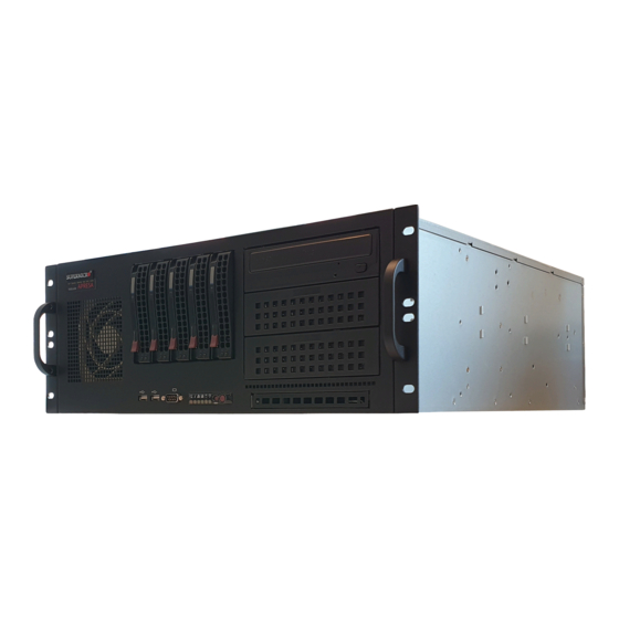
Page 21: Apresa Super Micro 4U Server
Apresa Super Micro 4U server 2.4. Front side: (Current models are shipped without the DVD) Back side: 2.4.1. Specifications 2.4.2. Enclosure TYPE : Super Micro CSE-842XTQ-R606B COLOR : Black front, sheet metal. WEIGHT : 18 Kg (approximately, varies with different models) -
Page 22: Motherboard / Cpu / Ram / Psu
: 8CH / 16CH or 24CH ISDN E1/T1 : SYNWAY TYPE DTP-30C/PCIe+/2.0 : 30CH / 1TRUNK ISDN60 (E1) : SYNWAY TYPE DTP-60C/PCIe+/2.0 : 60CH / 2TRUNK ISDN120(E1) : SYNWAY TYPE DTP-120C/PCIe+/2.0 : 120CH / 4TRUNK INSTALLATION MANUAL APRESA COPYRIGHT © 2011-2021 VIDICODE ®... -
Page 23: Environmental Specification
: +10 …. +35 °C (Operating) or - 10 …. + 65 °C (Storage) HUMIDITY : 8%-90% No condensing, operating and storage. 2.4.7. Approvals EMC APPROVAL : EN55022 / EN55024 / FCC15 SAFETY : EN60950 INSTALLATION MANUAL APRESA COPYRIGHT © 2011-2021 VIDICODE ®... -
Page 24: The Apresa-Compact
ACTIVITY LED Compact - Line POWER BUTTON BLUE BUTTON LIGHT WHEN ON DOOR DWG1175_00 Front side, door opened VoIP| ISDN| TDM| POTS| AUDIO APRESA Compact - Line DWG1176_00 AUDIO OPEN DOOR (NOT USED) INSTALLATION MANUAL APRESA COPYRIGHT © 2011-2021 VIDICODE ®... -
Page 25: Specifications
(in the PCI-e expansion slot) marked ‘LAN’ to interface the normal LAN. The motherboard LAN is marker ‘VoIP’ and should connect to the VoIP-LAN. • The APRESA-Compact D8 and the APRESA-Compact A8 have a line interface card installed (ATP or DST) capable to capture 8 recording channels. The motherboard LAN is marked ‘LAN’... -
Page 26: Motherboard / Cpu / Ram / Psu
Environmental specification TEMPERATURE : +10….+35 °C (Operating) or -10….+ 65 °C (Storage) HUMIDITY : 8%-90% No condensing, operating and storage. 2.5.7. Approvals EMC APPROVAL : EN55022 / EN55024 / FCC15 SAFETY : EN60950 INSTALLATION MANUAL APRESA COPYRIGHT © 2011-2021 VIDICODE ®... -
Page 27: The Apresa-Compact (Voip-Only)
PCI-e : not available 2.6.4. Hard drive INTERFACE : SATA 3GBIT/SEC SIZE : 2.5 INCH : 5400 CACHE : 128MByte QUALITY GRADE : 24/7 CAPACITY : 1 TBYTE RAID : NOT SUPPORTED INSTALLATION MANUAL APRESA COPYRIGHT © 2011-2021 VIDICODE ®... -
Page 28: Environmental Specification
Environmental specification TEMPERATURE : +10….+35 °C (Operating) or -10….+ 65 °C (Storage) HUMIDITY : 8%-90% No condensing, operating and storage. 2.6.6. Approvals EMC APPROVAL : EN55022 / EN55024 / FCC15 SAFETY : EN60950 INSTALLATION MANUAL APRESA COPYRIGHT © 2011-2021 VIDICODE ®... - Page 29 APRESA BASE Software This chapter describes the complete procedure to install the APRESA base software imageon a USB memory stick to a server PC Pre-requisites: - USB Stick + MONITOR + KEYBOARD + ETHERNET+ MOUSE - APRESA Base License, Channel License(s), G.729 License(s), S&U License etc.
-
Page 30: Hardware Requirements
• WORK IN AN ESD SAFE ENVIRONMENT Procedure in detail: Simply push the ON/OFF button on front of the Apresa or shutdown the APRESA by using the WEB page (LOGON, ->TOOL->SYSTEM->SHUTDOWN (The shutdown may take some time so wait patiently until the red power LED turns off). -
Page 31: Apresa Base Software Installation Procedure By Using Ausb Stick
Select: “BOOT SETTINGS “ - SET: boot-sequence to BOOT from the Apresa installation drive. When installing the software RAID 1 or software RAID 10 version of APRESA you must set the BIOS-setting for RAID to NO RAID (RAID is handled by software ) -CSM (compatibility service module) ->... -
Page 32: Preparations
Image that must be used to write a bootable USB stick containing all necessary Apresa installation files. Ask VIDICODE sales for a “APRESA Quick Guide” if you don’t have one at hand. One single image supports all APRESA configurations (NORAID/Software RAID/Hardware RAID/Encryption). -
Page 33: Prepare A Bootable Usb-Stick For Apresa Base Software Installation
Prepare a bootable USB-Stick for Apresa Base Software Installation. The traditional way of installing the Apresa base software is to create a CD/DVD using a .ISO installation image. Today we prefer the easier and faster approach and use a bootable USB-Stick. - Page 34 3. Generate the bootable image on the USB-Stick by pressing the ‘START’ button. 4. Rufus will see that the Apresa-Image is actually a ISO-Hybrid and popup another question about the writing mode to use , select ‘Write in DD Image mode’.
-
Page 35: Apresa Base Software Installation Using The Usb-Stick
2.9.4. Apresa Base Software Installation using the USB-stick Insert the APRESA installation USB-Stick in the APRESA server and restart the system. The installation process should start automatically. If installation does not start, make sure the USB- Stick is in the bootable devices list (Check BIOS setting: list of bootable devices). As an alternative one can make a manual selection for booting from USB-Stick by pressing F8 or F11 (depends on BIOS-brand) quickly after power-on. - Page 36 If you counter a prompt for ‘ Force UEFI ? ’, your reply should be: 'Yes' as UEFI is preferred for Apresa. UEFI is state-of-the -art, safer and allows for larger hard drive storage compared to MBR. After a while, when asked for, confirm the partitioning schema and allow writing of that scheme to the hard drive.
-
Page 37: Access The Apresa For The First Time
You can skip the rest of this section and proceed APRESA installation at ‘APRESA BASE SOFTWARE license activation”. The next section helps you in setting up the web connection to the APRESA by means of and a web browser on your work PC over the LAN. - Page 38 Define the APRESA IP on the work PC To access the APRESA web interface, you need to configure your work PC to have an IP address in the same subnet as the APRESA system. This means that your work PC should have an IP address assigned in the range from 192.168.55.1 to 192.168.55.254, for example 192.168.55.10.
- Page 39 Note: This installation manual was originally written when Vidicode was distributing the 2011 version of the Apresa software. Consequently, some references and screenshots are targeted to that version. When running later versions, your screens may look slightly different. The primary account username is “admin”.
- Page 40 • Adjust the network configuration to match that of the PC network in your organization. • Click Apply and let the network restart If after the restart, the new IP address of the Apresa is not known for some reason, the program Apresa IP Lookup can be used.
-
Page 41: Base Software Licensing
T HE INPUT BOX ENT ER 'COMPANY NAME' AND PRESS OK APRESA LICENSED COMPLET ED DWG1158_00 NOTE: If you can’t “click” on the APRESA web page to reach the VIDICODE license server go to: http://www.vidicode.com/activation INSTALLATION MANUAL APRESA COPYRIGHT © 2011-2021 VIDICODE ®... - Page 42 DWG1161_00 The ‘Home’ page will be displayed, see below. The page will notify that no license is activated yet. APRESA will ONLY record calls after proper licensing. Click on the link ‘Software activation’ to start the licensing procedure. If the APRESA is...
- Page 43 APRESA generates a hardware dependent ACT IVAT ION CODE COPY the code CT RL+C and then click this link DWG1163_00 By clicking the link you will be connected to the VIDICODE license server WEB page. INSTALLATION MANUAL APRESA COPYRIGHT © 2011-2021 VIDICODE ®...
- Page 44 Enter COMPANY name PASTE the code CTRL+V PRESS Submit DWG1164_00 On the screen below copy the activation code (select then CTRL+C) COPY the code CT RL+C DWG1165_00 INSTALLATION MANUAL APRESA COPYRIGHT © 2011-2021 VIDICODE ®...
- Page 45 Now go back to the WEB page of the APRESA and paste (CTRL+V) the activation code. Enter the Company name, followed by ok. PAST E the code CT RL+V Enter the com pany nam e Press OK DWG1166_00 Now the activation is finalized.
-
Page 46: Channel Licensing
CHECK ACT IVAT ED CHANNELS APRESA CHANNEL LICENSING COMPLET ED DWG1159_00 NOTE : If you can’t “click” on the APRESA web page to reach the VIDICODE license server go to : http://www.vidicode.com/channels INSTALLATION MANUAL APRESA COPYRIGHT © 2011-2021 VIDICODE ®... -
Page 47: Synway Driver Installation
2.9.8. SYNWAY driver installation This step can be skipped if your Apresa is ' VoIP - only ', but if Synway interface cards are deployed you must install the Synway Card I/F Driver manually. First, check that all the Synway I/F cards are physically installed in your server. Then, run from the Apresa-WEB page: Tools->System->Install Driver. -
Page 48: S&U Licensing
Just follow the quick guide that comes with the S&U license. 2.9.10. Base Software Update 1. Assure that the APRESA that you want to update has a valid S&U license; 2. Log in as administrator (admin) in the web interface;... -
Page 49: Install Addstorcli
Debian Linux. In this document, the procedure is described to install Apresa in such an environment. Notice that since the virtual machine is not set up and fully controlled by the Apresa installation, we cannot guarantee the same functionality. -
Page 50: General Apresa Configuration
Consider applying the following security measures, especially when Apresa is on the public internet. • Restrict access using a firewall on Apresa or outside of it, based on IP address or other rules, or give access only through a VPN tunnel. Disable remote access to SSH, or allow access to SSH (port 22) only for your own IP address. -
Page 51: Mounting
As the best location, we advise to install the APRESA server is your computer server room. Always install the APRESA server in close proximity of the PBX and phone patch panel as there are maximum cable length restrictions to deal with. -
Page 52: Mounting Apresa Into A 19-Inch Cabinet
Mounting APRESA into a 19-inch cabinet 3.2. The APRESA server is designed to fit in standardized 19-inch server cabinets and will take 1U or 4U in height. Depending on the telecommunication system to be tapped up to 4 patch panels (each 1U in height) may be involved in the total installation and need to be considered when planning cabinet space. -
Page 53: Telecom Wiring
Introduction 4.1. The APRESA can be used to record from a wide variety of different signal sources spanning from simple audio lines to the more complex ones like ISDN and VoIP networks. In the table below you find the various source characteristics listed... -
Page 54: Connector Locations
All interface cards mentioned extract the signals to be recorded based on ‘high impedance tapping’ meaning that the original signal is extracted with minimal electric disturbance. Depending on the type of PBX, the cable length between the APRESA recorder and the TAP- point (the “stub length”) can be up to 6 to 20 meter. -
Page 55: General Remarks About Wiring
The focus here is tracing the wires that carry the desired signal and how to make an easy TAP to feed the signal to the APRESA. Connect to the ports labeled “ANALOG”, “TDM”... -
Page 56: Balanced Signals
It is preferred to feed balanced pairs to the interface card. This will give the best results in terms of hum and other distortion. Every analog input of the APRESA is built with individual line transformers and DC blocking capacitors, in a truly balanced configuration. - Page 57 AUDIO CHx-A SOURCE SOURCE APRESA CHx-B SINGLE ENDED When dealing with an unbalanced signal we advise only to use the best quality of shielded cable that is kept as short as possible. INSTALLATION MANUAL APRESA COPYRIGHT © 2011-2021 VIDICODE ®...
-
Page 58: Wiring Using The Rj11 Patch Box
To ease the wiring job, all analog interface boards are supplied with a RJ11 patch box and a RJ21/RJ21 cable 1meter in length. (Optionally lengths of 3,5 and 10m are available, but remember that shorter=better) Connect the Patch Box to the APRESA: BACK SIDE APRESA AT P (ANALOG) -
Page 59: Direct Wiring (Not Using A Patch Box)
NOTES: • THIS IS SUPPORTING INFORMATION ONLY AND WE ADVISE YOU TO CAREFULLY CHECK THE CABLE YOU HAVE, AS ITS COLORING SCHEME MAY EVEN BE DIFFERENT FROM THE 2 SCHEMES LISTED ABOVE. INSTALLATION MANUAL APRESA COPYRIGHT © 2011-2021 VIDICODE ®... -
Page 60: Wiring Analog Telephony (Pots) Taps
For the APRESA the polarity of the signal is irrelevant and can be ignored during wiring. The wiring- type used to install the analog telephone system can very different as we see in the field: •... -
Page 61: Wiring Tdm Telephony Taps
The whole issue of wiring TDM telephony TAPS is simply just to identify the wire-pair (or wire pairs) that carry the voice data and to connect these wires to recording channel(s) on the APRESA. The first step is to find out the name of the manufacturer and the model number of the PBX and Telephones. - Page 62 PBX brands. 24 CH RJ11 to RJ21 PAT CH BOX Always test ONE custom cable first to RJ21/RJ21 cable T O APRESA avoid time and material loss. DWG1141_01 INSTALLATION MANUAL APRESA COPYRIGHT © 2011-2021 VIDICODE ®...
- Page 63 IMPORTANT NOTES ON USING THE RJ11 PATCH BOX WITH -WIRE CONNECTION YOU CAN USE OUTLETS OF THE RJ11 PATCH BOX ONLY WITH -WIRE CONNECTION YOU CAN USE THE NUMBERED OUTLETS OF THE RJ11 PATCH BOX INSTALLATION MANUAL APRESA COPYRIGHT © 2011-2021 VIDICODE ®...
-
Page 64: Wiring Isdn2 Telephony Taps (Basic Rate Isdn)
Further information can be found in the chapter that describes the Tapping Patch-box. Wiring ISDN2 Telephony TAPS (Basic rate ISDN) 4.7. ISDN2 or ISDN-basic rate is from a wiring point of view pretty much identical the 4-wire TDM installation. Refer to the previous chapter. INSTALLATION MANUAL APRESA COPYRIGHT © 2011-2021 VIDICODE ®... -
Page 65: Wiring Isdn E1/T1 Telephony Taps
All cables used are twisted pair cables. Refer to the pinning of the DTP connector in the drawing for signal reference. The cable between the RJ45 splitter and the APRESA should be less, then 20 meter in length. This cable should be twisted pair and explicit NOT parallel pair cables that are commonly used for ISDN basic rate installations. - Page 66 There are in fact 2 coax cables to tap with E1/T1/J1. The actual tap is made by using a “BNC” T- connector, one in each coax cable. The coaxial cables used are of 75-ohm characteristic impedance. The cable between the BNC T-splitter and the APRESA should maximum 20 meter in length. A Photo of the RJ48C BNC adapter...
-
Page 67: Configuration Of Voip Telephony Recording
APRESA ‘see’ these RTP packets on its recording NIC (NIC, Network Interface Card). Apresa uses RTP data to record the audio of VoIP calls. The VoIP PBX should be configured to use only G.711, G.722, G.729, GSM 6.10, or iLBC. These Codecs are supported in Apresa. Apresa will not record audio in other Codecs. -
Page 68: Station Side Recording
The next section presents several VOIP topology examples. All examples are based on enabling the APRESA to ‘see’ the data to be recorded. To find the valid example that applies to your VoIP- situation, just get the answer to the 3 questions below:... - Page 69 SWITCHES WITH SWITCHES WITH PROPER SETUP PROPER SETUP DWG1155_01 VT1 …. VT7 on the bottom refers to on of the 7 diagrams that follow below: (for compact drawing a 5-port switch is used) INSTALLATION MANUAL APRESA COPYRIGHT © 2011-2021 VIDICODE ®...
-
Page 70: Voip Topology 1
PBX/ VoIP ITSP GATEWAY ITSP GATEWAY MIRROR Port mirroring switch Port Mirroring Setting : SourcePort = Port 1 DestinationPort = Port 5 DWG-1147_00 Telephone Telephone Telephone Telephone ONLY EXTERNAL CALLS ARE RECORDED INSTALLATION MANUAL APRESA COPYRIGHT © 2011-2021 VIDICODE ®... -
Page 71: Voip Topology 2
PBX/ VoIP ITSP GATEWAY ITSP GATEWAY MIRROR Port mirroring switch Port Mirroring Setting : SourcePort = Port 2 DestinationPort = Port 5 Telephone Telephone Telephone Telephone DWG-1148_00 INTERNAL AND EXTERNAL CALLS ARE RECORDED INSTALLATION MANUAL APRESA COPYRIGHT © 2011-2021 VIDICODE ®... -
Page 72: Voip Topology 3
ITSP GATEWAY ITSP GATEWAY MIRRORS Port mirroring switch Port Mirroring Setting : SourcePort = Port 3+Port 4 DestinationPort = Port 5 Telephone Telephone Telephone Telephone DWG-1149_00 INTERNAL AND EXTERNAL CALLS ARE RECORDED INSTALLATION MANUAL APRESA COPYRIGHT © 2011-2021 VIDICODE ®... -
Page 73: Voip Topology 4
PBX/ VoIP PBX/ VoIP MIRROR Port mirroring switch Port Mirroring Setting : SourcePort = Port 1 DestinationPort = Port 5 Telephone Telephone Telephone Telephone Telephone Telephone DWG-1150_00 ONLY EXTERNAL CALLS ARE RECORDED INSTALLATION MANUAL APRESA COPYRIGHT © 2011-2021 VIDICODE ®... -
Page 74: Voip Topology 5
4.9.7. VoIP topology 5 PSTN PBX/ VoIP PBX/ VoIP MIRRORS Port mirroring switch Telephone Telephone Telephone Telephone Telephone Telephone DWG-1151_00 INTERNAL AND EXTERNAL CALLS ARE RECORDED INSTALLATION MANUAL APRESA COPYRIGHT © 2011-2021 VIDICODE ®... -
Page 75: Voip Topology 6
PBX/ VoIP PBX/ VoIP MIRROR Port mirroring switch Port Mirroring Setting : SourcePort = Port 1 DestinationPort = Port 5 Telephone Telephone Telephone Telephone Telephone Telephone DWG-1152_00 INTERNAL AND EXTERNAL CALLS ARE RECORDED INSTALLATION MANUAL APRESA COPYRIGHT © 2011-2021 VIDICODE ®... -
Page 76: Voip Topology 7
Port Mirroring Setting : SourcePort = Port 1 DestinationPort = Port 5 Telephone Telephone Telephone Telephone Telephone Telephone DWG-1153_00 INTERNAL AND EXTERNAL CALLS ARE RECORDED Configuration of TETRA communication recording 4.10. NOT YET SUPPORTED INSTALLATION MANUAL APRESA COPYRIGHT © 2011-2021 VIDICODE ®... -
Page 77: Patch Panels
The unit is not suitable for 19” rack mounting. Note that this wiring solution may need external ‘T’ splitter (RJ12 or RJ45) and custom cabling between the splitter and this patch panel. INSTALLATION MANUAL APRESA COPYRIGHT © 2011-2021 VIDICODE ®... -
Page 78: The Tapping Patch Box
(=2-wires) to establish the link with the PBX. Used pair is on the PIN4/5 and this is the pair has the passive TAP to feed the APRESA recording channels. The remaining 3 balanced pairs (3x2-wires) are of no concern for the data communication (and for the APRESA). -
Page 79: Expanding Apresa
5.1.1. Channel license upgrade For every recording channel expansion, you must handle as follows: Buy channel license(s) from your dealer or from directly VIDICODE; Link the license to your machine (www.vidicode.com/channels); Enter the response license code in your machine. Refer to chapter 3 for more details. -
Page 80: Installation Of Interface Cards
Base card +1 interface module = 16 channels. Base card +2 interface module = 24 channels. NOTE: ATP and DST expansion modules are NOT identical Use MOD_24A on ATP Cards and use MOD_24DB on DST Cards INSTALLATION MANUAL APRESA COPYRIGHT © 2011-2021 VIDICODE ®... - Page 81 DST-24B/PCI+ ON BASE BOARD DST-24B/PCIe+(2.0) ON BASE BOARD ATP or DST interface card OPT IONAL 8CH EXPANSION MODULES ( 2 PCS ) AUDIO JACK LOCKING BRACKET S RJ21 PCI / PCIe DWG1170_00 INSTALLATION MANUAL APRESA COPYRIGHT © 2011-2021 VIDICODE ®...
-
Page 82: Increasing The Storage Capacity
5.1.4. Increasing the storage capacity Increase of storage capacity is possible by installing a larger hard drive(s). Backup the APRESA and bring it up on the newly installed larger drive(s). 5.1.5. Building or changing a software RAID volume Changing from NoRAID to RAID1 or vice versa require: •... -
Page 83: Backup And Restore Backup
REPLACEMENT OF HARDWARE MAY HAVE LICENSING ISSUES he APRESA software is protected against illegal copying. This protection is based on the linkage of the software license and the hardware signature of the system that was used at first installation. - Page 84 ISSUE T O AT T ENT T O DWG1167_00 Contact VIDICODE sales to obtain a valid license. Note that APRESA with an invalid license will record only for a period of 30 days after installation. INSTALLATION MANUAL APRESA COPYRIGHT © 2011-2021 VIDICODE ®...
-
Page 85: Maintenance
Vidicode advises customers to check for Apresa base software updates from time to time as the software is intensively maintained and expanded. Note that Apresa base software updates are free of charge for every Apresa machine but only with a valid support and Upgrade (S&U) License that must be purchased every 1-or 3 year(s) . -
Page 86: Redundant Power Supply
In the status page of the APRESA (Tools/System/System Information) the health of the RPSU is displayed. In the event that one power pack fail, the other power pack will take over completely by delivering the desired power standing alone. - Page 87 There is no need to bring the APRESA system down to swap a power pack as the power packs are ‘Hot Swappable’. It is easy to replace a failing power pack.
-
Page 88: Storage Options
The capacity of a RAID5 volume equals the capacity of N-1 TBYTE, were N=the number of hard drives in the RAID5 volume. RAID5 is depreciated for use with Apresa because 1) the chance to rebuild a RAID5 volume build with the modern high capacity hard drives is not at an acceptable level and 2) the lower write performance of RAID5 will limit the number of channels that can be serviced on an Apresa. -
Page 89: General Information
RAID5 is not an option to consider. Hardware RAID10 This combo of RAID0 and RAID1 is an excellent choice for Apresa with a high number of channels. Use the advised controller with cache/BBU for best write speed and reliable rebuild. -
Page 90: Volume
Password: -- For default password, see Call Recorder Apresa System Shell manual -- The system shell can be reached remotely, with SSH (PuTTY), if "Enable remote shell" is enabled in the system settings, or it can be done locally by connecting a monitor and keyboard to the Apresa machine, and rebooting. - Page 91 /dev/sda If the second drive (SATA1) was replaced, then type the following command: sudo grub-install /dev/sdb If the third drive (SATA2) was replaced, then type the following command: sudo grub-install /dev/sdc INSTALLATION MANUAL APRESA COPYRIGHT © 2011-2021 VIDICODE ®...
- Page 92 Rebuilding of the replaced drive in progress Go to: Tools -> System -> System Information. INSTALLATION MANUAL APRESA COPYRIGHT © 2011-2021 VIDICODE ®...
-
Page 93: Advised Hardware Raid Controller Card
The cards can be used for both hardware-RAID1 and hardware-RAID10 SOFTWARE RAID5 & HARDWARE RAID5 are DEPRECIATED Note that early in the setup of the Apresa system, even before base software installation the user must assign hard drives to a virtual drive to build the RAID volume, the ‘Redundant Array of Independent Drives’. -
Page 94: Interface Card Specifications
11. INTERFACE CARD SPECIFICATIONS To establish a technical correct tap on the various types of communication links the installer must have some basic information about the interface cards deployed inside the APRESA recorder. Common characteristics for all interface cards: • All cards are basically PC- PCIe expansion cards;... -
Page 95: Atp-24A/Pci+/2.0 / Atp-24A/Pci
Isolation 500 VDC Power dissipation <8 W (3V3@900mA / 5V@200mA / 12V@100mA Sample rate 8KHz Frequency response 300-3400 Hz (±3dB) Signal to Noise ratio >34 dB Dynamic input range -40 …… +10dB INSTALLATION MANUAL APRESA COPYRIGHT © 2011-2021 VIDICODE ®... -
Page 96: Dst-24B/Pci+/2.0 / Dst-24B/Pci
High-Impedance passive monitoring by parallel connection Isolation 500VDC Power dissipation < 9 W (3V3@1300mA / 5V@50mA / 12V@300mA Sample rate 8 KHz Frequency response 300-3400 Hz (±3dB) Signal to Noise ratio >34 dB INSTALLATION MANUAL APRESA COPYRIGHT © 2011-2021 VIDICODE ®... -
Page 97: Dtp-X0C/Pci+ / Dtp-X0C/Pci
High-Impedance passive monitoring by parallel connection Isolation 500VDC Power dissipation < 5 W (3V3@1500mA Sample rate 8KHz Frequency response 300-3400 Hz (±3dB) Signal to Noise ratio >34 dB Signaling systems SS1 / SS7 / DSSS1 INSTALLATION MANUAL APRESA COPYRIGHT © 2011-2021 VIDICODE ®... -
Page 98: Gnu General Public License
Sections 1 and 2 of the GPL License *) on a medium customarily used for software interchange. The GPL License can be found on the Application CD in your CR APRESA package under the directory Licenses. If you want to receive the source code, contact VIDICODE:... -
Page 99: Terminology Explained
An acronym for ‘Just a bunch of drives’. A group of hard drives under a RAID controller are not set up as any type of RAID volume. These drives are available to the operating system as an individual disk. JBOD does not provide data redundancy. JBOD is not supported by APRESA LOCAL CALL=... - Page 100 The length of an un-terminated segment of a transmission line. Applies to the length of the cable between the tap and the APRESA recorder. The maximum length allowed varies with the brand of the PBX and the telecom wiring. Exceeding the maximum stub length will degrade the quality and the reliability of the voice link.
- Page 101 Managed switches offer port mirroring. REDUNDANT POWER SUPPLY= Power supply used in high availability installation. Build with two power packs and allows one power pack to fail without interruption of the computing. INSTALLATION MANUAL APRESA COPYRIGHT © 2011-2021 VIDICODE ®...
-
Page 102: Copyright And Trademarks
15. RoHS 2 STATEMENT Vidicode hereby declares and certifies that all APRESA hardware is RoHS 2 5/6 compliant according to the definitions and restrictions given by the Directive 2011/65/ EU of The European Parliament and of the Council of...
Need help?
Do you have a question about the APRESA and is the answer not in the manual?
Questions and answers