Table of Contents
Advertisement
Quick Links
Advertisement
Table of Contents

Related Manuals for Postek iQ200


Summary of Contents for Postek iQ200
- Page 2 Microsoft, Windows are registered trademarks of Microsoft Corporation. Copyright © 2021 by Postek Electronics Co., Ltd. All rights reserved. Under the copyright laws, this manual cannot be reproduced in any form without the prior written permission of POSTEK. No patent liability is assumed, with respect to the use of the information contained herein.
- Page 3 (according to POSTEK Warranty Clauses). In no event shall POSTEK or the resellers involved be liable for any direct or indirect loss, including but not limited to loss of business profits, business interruption, loss of business information, or other pecuniary loss.
-
Page 4: Table Of Contents
User’s Manual Contents Contents Preface .......................... 1 Important Notes ......................2 Chapter 1: Introduction ....................3 1.1 Specifications ......................... 3 1.2 Contents in the Box ........................ 4 Chapter 2: Setup and Use ................... 5 2.1 Main Parts and Structures ...................... 5 2.1.1 Front View ........................ -
Page 5: Preface
This manual explains how to set up and begin using your iQ printer. It also provides detailed information on configuring your printer, basic operations, care and troubleshooting. Please read this manual carefully before using the POSTEK iQ printer. Symbol Conventions The symbols that may be found in this document are defined as follows. -
Page 6: Important Notes
User’s Manual Important Notes Important Notes Please read the following passages thoroughly before proceeding. Printhead The thermal printhead can be easily damaged due to its precision construction. A printhead damaged by misuse is not covered under the terms of the warranty. To ensure longevity of the printhead, please note the following: •... -
Page 7: Chapter 1: Introduction
Optional Items Guide Adapter, 10/100 M Adaptive Ethernet Port HEAT , or Heating Equilibrium Adaptive Tuning, is a POSTEK designed and developed cutting-edge technology that sets the benchmark for heat management in thermal printing. Printers equipped with HEAT have significant improvements in their printout clarity and print speed. The HEAT level represents the fineness of the heating uniformity with level I being the finest. -
Page 8: Contents In The Box
User’s Manual Chapter 1: Introduction 1.2 Contents in the Box Inspect the shipping carton(s) for possible shipping damage, if damage is discovered, notify the shipping company to report the nature and extent of the damage. Please check the items according to the Quick Start Guide. If there are any items missing, notify... -
Page 9: Chapter 2: Setup And Use
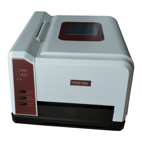
User’s Manual Chapter 2: Setup and Use Chapter 2: Setup and Use 2.1 Main Parts and Structures 2.1.1 Front View Figure 2-1 Front View Table 2-1 Front View Description Number Description [READY] Indicator [MEDIA] Indicator WIFI Indicator [PAUSE/Self Test] Button... -
Page 10: Internal View
User’s Manual Chapter 2: Setup and Use 2.1.2 Internal View Figure 2-2 shows the detailed structure of the printer. Figure 2-2 Internal View Table 2-2 Internal View Description Number Description Handle Printhead Assembly Platen Roller Media Guide Media Guide Rod... -
Page 11: Rear View
User’s Manual Chapter 2: Setup and Use 2.1.3 Rear View The printer is equipped with multiple interfaces. See Figure 2-3. Figure 2-3 Rear View Table 2-3 Rear View Description Number Description RS232 Serial Port DIP Switch USB Port WiFi RESET button... -
Page 12: Setting Up The Printer
Do not use the printer near liquids or corrosive chemicals. ⚫ Using the wrong power adapter may cause damage to your printer. POSTEK assumes no ⚫ liability for any damage in such cases. The rating for the printer is 24VDC. -
Page 13: Loading The Media
User’s Manual Chapter 2: Setup and Use 2.2.3 Loading the Media iQ printer can be operated under four different modes: Standard Mode, Tear-off Mode, Cutter Mode, and Peeler Mode. • In Standard Mode, the printer stops and goes into standby as soon as the print job is complete. - Page 14 User’s Manual Chapter 2: Setup and Use Media Spindle Media Roll Adaptors Media Roll Media Roll Guide Media Roll Module correctly fitted with Spindle and Guides Figure 2-5 Place Media Roll on Media Spindle 3. Place the entire unit into the printer’s Media Compartment.
- Page 15 User’s Manual Chapter 2: Setup and Use 5. Thread the media under the Media Guide Rod, over and pass the Platen Roller to the front of the printer. 6. Slide the Media Guide to the edge of the media, making sure that the media remains flat and is placed in the middle of the Tear-off Bar.
-
Page 16: Using The External Media Stand
User’s Manual Chapter 2: Setup and Use 2.3 Using the External Media Stand It is recommended to install the External Media Stand when the outer diameter of the media roll is larger than 4 inches or when fanfold media is applied. - Page 17 User’s Manual Chapter 2: Setup and Use Figure 2-9 Lift the Handle 3. Load a roll of media (labels facing up) on the Media Spindle, then slide the two Media Roll Guides, with smooth sides facing toward the media, onto the Media Spindle from each end until both Media Roll Guides touch the media.
- Page 18 User’s Manual Chapter 2: Setup and Use 6. Position the media roll in the middle of the Spindle, using the ruler on the Media Spindle for alignment. See Figure 2-11. Figure 2-11 Load the Media 7. Thread the media under the Media Guide Rod, over and pass the Platen Roller to the front of the printer.
- Page 19 User’s Manual Chapter 2: Setup and Use Figure 2-13 Media loaded Fanfold Label To load fanfold media on External Media Stand, follow the steps below: 1. Place the front part of the External Media Stand under the printer, making sure the two rear rubber feet of the printer are fitted into the two holes on the media stand, see Figure 2-14.
- Page 20 User’s Manual Chapter 2: Setup and Use Figure 2-15 Lift the Handle 3. Thread the folded label through the media slot at the rear end of the printer, and go on to thread the media under the Media Guide Rod, over and pass the Platen Roller to the front of the printer.
-
Page 21: Changing The Position Of Reflective Media Sensor
User’s Manual Chapter 2: Setup and Use Figure 2-17 Fanfold Label Loaded 2.4 Changing the Position of Reflective Media Sensor 1. Open the media sensor cover on the bottom side of the printer and loosen the screws. 2. Move the media sensor to the appropriate position. See Figure 2-18. - Page 22 User’s Manual Chapter 2: Setup and Use Media Media Media Figure 2-19 Media Sensor Position When media rolls are produced, the media end would be fixed to the media core by duct tape or ⚫ scotch tape. If your printer cannot detect Media Out signal well, please refer to Figure 2-20 to...
- Page 23 User’s Manual Chapter 2: Setup and Use Tape Hole The tape shall avoid covering the hole Tape Media gap The position of the tape should be made known to user to avoid positioning Media Sensors over the tape area.
-
Page 24: Chapter 3: Operations And Settings
User’s Manual Chapter 3: Operations and Settings Chapter 3: Operations and Settings 3.1 Basic Operations 3.1.1 Power Switch The power switch is on the rear left side of the printer. The symbols on the switch are defined as follows: •... - Page 25 User’s Manual Chapter 3: Operations and Settings Table 3-1 LED Indicator Description LED Indicator Description • If the indicator is on, the printer is ready and waiting for user input • If only the [READY] indicator is blinking, then the printer is...
-
Page 26: Advanced Functions
User’s Manual Chapter 3: Operations and Settings 3.1.3 Advanced Functions Media Calibration When the printer is on standby, press and hold the [FEED/Calibration] button (hold for around 4 seconds), the printer will automatically feed labels and the media calibration is done. During this process, the [READY] and [MEDIA] indicators will start blinking. -
Page 27: Dip Switches
User’s Manual Chapter 3: Operations and Settings 3.1.4 DIP Switches The DIP Switch is located on the back of the printer, as shown in Figure 3-2. Figure 3-2 DIP Switch Table 3-3 DIP Switch Description Position Corresponding Functions Set printing mode... - Page 28 User’s Manual Chapter 3: Operations and Settings Position Corresponding Functions 7 OFF & 8 ON: 38400 7 ON & 8 ON: 57600 Before making changes to the switches, please make sure the printer is powered off. ⚫ All the switches should be off by default except the 5 position.
-
Page 29: Setting Operation Mode
User’s Manual Chapter 3: Operations and Settings 3.1.5 Setting Operation Mode Set appropriate operation mode for the printer. Tear-off Mode The steps to set the printer to Tear-off Mode are as follows: 1. Set the 2 position of the DIP Switch to ON to enable Tear-off Mode, label would stop at the identifier position (for media with gaps, notches, black mark, etc) or set position (for continuous media) for users to tear off the printed label or tag manually. -
Page 30: Wifi Settings
User’s Manual Chapter 3: Operations and Settings 5. Create and edit label template in the label editing software, and click at “Print” to send the print task to the printer. After each finished printing, the printer will automatically cut off the printed label(s). -
Page 31: Installing Windows Driver And Label Editing Software
Quick Start Guide or visit POSTEK website: http://www.postekchina.com. Each printer also comes with a BarTender UltraLite edition software. To access to the software and the directions for use, please scan the QR code on the Quick Start Guide or visit POSTEK website: http://www.postekchina.com. -
Page 32: Chapter 4: Maintenance
User’s Manual Chapter 4: Maintenance Chapter 4: Maintenance Make sure the printer is powered off before performing maintenance operations. ⚫ The Printhead may be hot due to recent printing. Wait until the Printhead cools before ⚫ performing maintenance. Use only anhydrous isopropyl alcohol to clean the print head. -
Page 33: Cleaning The Printer Interior
User’s Manual Chapter 4: Maintenance 4.3 Cleaning the Printer Interior Over time, the printer’s interior may collect dust or debris from the consumables. It is advised to periodically clean the printer’s interior in order to prevent the accumulated debris from damaging internal parts. -
Page 34: Chapter 5: Troubleshooting
User’s Manual Chapter 5: Troubleshooting Chapter 5: Troubleshooting Occasionally situations occur that require some troubleshooting. Possible issues and potential solutions are listed in this section. While not every situation is addressed, you may find some of these tips useful. -
Page 35: Miscellaneous Issues
Poor Printing Printhead is dirty. Clean the Printhead. Follow the recommended Quality maintenance guidelines for cleaning the Printhead. Poor quality consumables Change to higher-quality consumables. For errors not listed here, please contact an authorized POSTEK Service Provider for further assistance. -
Page 36: Appendix A: Interface Specifications
User’s Manual Appendix A: Interface Specifications Appendix A: Interface Specifications The RS232 connector on the printer is a DB9F: Number Description Definition Ground Baud rate: 9600, 19200, 38400, 57600 Data format: 8 data bits, 1 start bit or 1 stop bit. -
Page 37: Appendix B: Ascii Table
User’s Manual Appendix B: ASCII Table Appendix B: ASCII Table “ XOFF & ‘ < > The € sign is included in the embedded table at DEC128 (HEX 80).
Need help?
Do you have a question about the iQ200 and is the answer not in the manual?
Questions and answers