Table of Contents
Advertisement
Quick Links
Advertisement
Table of Contents

Related Manuals for Postek C168 Series


Summary of Contents for Postek C168 Series
- Page 2 Microsoft, Windows are registered trademarks of Microsoft Corporation. Copyright © 2021 by Postek Electronics Co., Ltd. All rights reserved. Under the copyright laws, this manual cannot be reproduced in any form without the prior written permission of POSTEK. No patent liability is assumed, with respect to the use of the information contained herein.
- Page 3 (according to POSTEK Warranty Clauses). In no event shall POSTEK or the resellers involved be liable for any direct or indirect loss, including but not limited to loss of business profits, business interruption, loss of business information, or other pecuniary loss.
-
Page 4: Table Of Contents
C168 Series User’s Manual Contents Contents Preface .......................... 1 Important Notes ......................2 Chapter 1: Introduction ....................4 1.1 Specifications ......................... 4 1.2 Contents in the Box ........................ 5 Chapter 2: Setup and Use ................... 6 2.1 Main Parts and Structures ...................... 6 2.1.1 Front View ........................ -
Page 5: Preface
With intuitive operations, the C168 is ideal for a wide range of applications. This manual explains how to set up and begin using your C168 Series printer. It also provides detailed information on configuring your printer, basic operations, care and troubleshooting. -
Page 6: Important Notes
• Always inspect consumables for high quality before purchasing. The C168 Series printer functions under Direct Thermal or Thermal Transfer print modes. Thermal Transfer is set as the factory default (requires ribbon for printing). However, if you need to print on Direct Thermal materials (ribbon is not required), please contact your printer supplier or service provider to reduce the printhead pressure. - Page 7 C168 Series User’s Manual Important Notes • It is very important to choose the right cutter model for the application to ensure personal safety and prevent damage to the cutter caused by cutting wrong types of media. • Keep loose items such as long hair, clothing, jewelry, away from the cutter.
-
Page 8: Chapter 1: Introduction
Wi-Fi, Bluetooth, Guillotine Cutter, Rotary Cutter, External Label Rewinder, Media Guide Adapter, 10/100 M Adaptive Ethernet Port HEAT , or Heating Equilibrium Adaptive Tuning, is a POSTEK designed and developed cutting-edge technology that sets the benchmark for heat management in thermal printing. Printers equipped with HEAT have significant improvements in their printout clarity and print speed. -
Page 9: Contents In The Box
C168 Series User’s Manual Chapter 1: Introduction 1.2 Contents in the Box Inspect the shipping carton(s) for possible shipping damage, if damage is discovered, notify the shipping company to report the nature and extent of the damage. Please check the items according to the Quick Start Guide. If there are any items missing, notify... -
Page 10: Chapter 2: Setup And Use
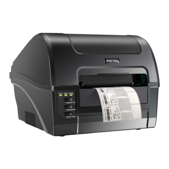
Chapter 2: Setup and Use Chapter 2: Setup and Use 2.1 Main Parts and Structures Front View 2.1.1 Figure 2-1 shows the front view of the C168 Series printer. Figure 2-1 Front View Table 2-1 Front View Description Number Description... -
Page 11: Internal View
C168 Series User’s Manual Chapter 2: Setup and Use Internal View 2.1.2 Figure 2-2 shows the detailed structure of the printer. Figure 2-2 Internal View Table 2-2 Internal View Description Number Description Left Mount_Ribbon supply Platen Roller Reflective Media Sensor... -
Page 12: Rear View
C168 Series User’s Manual Chapter 2: Setup and Use Rear View 2.1.3 The printer is equipped with multiple interfaces. See Figure 2-3. Figure 2-3 Rear View Table 2-3 Rear View Description Number Description RS-232 Serial Port Centronics Parallel Port (Extensible) -
Page 13: Setting Up The Printer
Interface Connection 2.2.1 When connecting the C168 Series printer to a computer via the USB interface cable, make sure to utilize the same USB port used during the driver installation process. If the same USB port is not available or not known, then please go to the printer driver’s Properties Dialogue Box, and make sure the correct port is checked under the Ports tab. -
Page 14: Loading The Ribbon
C168 Series User’s Manual Chapter 2: Setup and Use Loading the Ribbon 2.2.3 • Load ribbon only when using the thermal transfer printing mode. Remove any ribbon that may be loaded when using the direct thermal printing mode. • When using a ribbon roll with a width less than 110m, please place the ribbon roll in the middle of the Ribbon Spindle corresponding to the symmetry symbol (→|←). - Page 15 C168 Series User’s Manual Chapter 2: Setup and Use Figure 2-5 Lift the Printhead Module 3. Unwrap the ribbon package and separate the ribbon roll and the spare core. 4. Slide the ribbon roll onto one of the Ribbon Spindles and place the spare core onto the other spindle, see Figure 2-6.
- Page 16 C168 Series User’s Manual Chapter 2: Setup and Use Release Knob Figure 2-7 Load Ribbon Roll 6. Route the ribbon through the Printhead Module and wrap the end of the ribbon around the spare core, see Figure 2-8. Figure 2-8 Wrap Ribbon on the Core...
- Page 17 C168 Series User’s Manual Chapter 2: Setup and Use 7. Pull the Release Knob of the Ribbon Take-up compartment outwards and load the core in the Ribbon Take-Up compartment, see Figure 2-9. Release knob Figure 2-9 Place the Core on Ribbon Take-up 8.
-
Page 18: Loading The Media
C168 Series User’s Manual Chapter 2: Setup and Use To make sure the Ribbon End Sensor works properly, please use ribbon rolls which end with reflective materials or transparent materials with good reflective performance. Loading the Media 2.2.4 C168 printers can be operated under four different modes: Standard Mode, Tear-off Mode, Cutter Mode, and Peeler Mode. - Page 19 C168 Series User’s Manual Chapter 2: Setup and Use 2. Place the entire unit into the media compartment in the printer. 3. Position the media roll in the middle of the Spindle, using the ruler on the Media Spindle for alignment, see Figure 2-12.
- Page 20 C168 Series User’s Manual Chapter 2: Setup and Use placed in the middle of the Tear-off Bar. This can be checked with the ruler on the Tear-off Bar. 6. Press the Printhead Module downward until you hear a “click”, which indicates the module have locked into place, as shown in Figure 2-14.
-
Page 21: Using The External Media Stand
C168 Series User’s Manual Chapter 2: Setup and Use 2.3 Using the External Media Stand It is recommended to install the External Media Stand when the outer diameter of the media roll is larger than 4 inches or when fanfold media is applied. - Page 22 C168 Series User’s Manual Chapter 2: Setup and Use Media Spindle Media Roll Adaptors Media Roll Media Roll Guide Media Roll Module correctly fitted with Spindle and Guides Figure 2-16 Place Media Roll on Media Spindle 4. Place the entire unit onto the External Media Stand.
- Page 23 C168 Series User’s Manual Chapter 2: Setup and Use the printer. 7. Slide the Media Guides to the edge of the media, making sure that the media remains flat and is placed in the middle of the Tear-off Bar. This can be checked with the ruler on the Tear-off Bar.
- Page 24 C168 Series User’s Manual Chapter 2: Setup and Use Fanfold Label To load fanfold media on External Media Stand, follow the steps below: 1. Place the front part of the External Media Stand under the printer, making sure the two rear rubber feet of the printer are fitted into the two holes on the media stand, see Figure 2-20.
- Page 25 C168 Series User’s Manual Chapter 2: Setup and Use 5. Press the Printhead Module downward until you hear a “click”, which indicates the module have locked into place, then close the top cover. See Figure 2-22. Figure 2-22 Fanfold Label Loaded...
-
Page 26: Adjusting The Position Of Media Sensor
C168 Series User’s Manual Chapter 2: Setup and Use 2.4 Adjusting the Position of Media Sensor 1. Lift the top cover. 2. Push down the Printhead Release Lever to release the Printhead Module. 3. To adjust the position of the Reflective Sensor: Lift the Printhead Module to expose the Media Sensor cover, remove the Media Sensor cover and slide the Media Sensor to the appropriate position, then replace the media sensor cover. - Page 27 C168 Series User’s Manual Chapter 2: Setup and Use Media gap Media gap Media gap Figure 2-24 Media Sensor Position • When roll media is produced, the media end would be fixed on the media core by duct tape or scotch tape.
- Page 28 C168 Series User’s Manual Chapter 2: Setup and Use Tape Hole The tape shall avoid covering the hole Tape Media gap The position of the tape should be made known to user to avoid positioning Media Sensors over the tape area.
-
Page 29: Chapter 3: Operations And Settings
C168 Series User’s Manual Chapter 3: Operations and Settings Chapter 3: Operations and Settings 3.1 Basic Operations Power Switch 3.1.1 The power switch is on the back panel of the printer. The symbols on the switch are defined as follows: •... - Page 30 C168 Series User’s Manual Chapter 3: Operations and Settings LED Indicator Description paused and awaiting further instruction • If the indicator is on, it means the printer is at a normal working state [MEDIA] • If both the [READY] and [MEDIA] indicators are blinking, then the printer detected media out •...
-
Page 31: Advanced Functions
C168 Series User’s Manual Chapter 3: Operations and Settings Advanced Functions 3.1.3 Media Calibration When the printer is on standby, press and hold the [Feed/Calibration] button (hold for around 4 seconds), the printer will automatically feed labels and the media calibration is done. During this process, all three indicators will start blinking. -
Page 32: Dip Switches
C168 Series User’s Manual Chapter 3: Operations and Settings DIP Switches 3.1.4 The DIP Switch panel is located on the back of the printer, as shown in Figure 3-2. Figure 3-2 DIP Switch Table 3-3 DIP Switch Description Position Corresponding Functions... -
Page 33: Setting Operation Mode
C168 Series User’s Manual Chapter 3: Operations and Settings • Before making changes to the switches, please make sure the printer is powered off. • All the switches should be off by default except the 5 position. Setting Operation Mode 3.1.5... - Page 34 C168 Series User’s Manual Chapter 3: Operations and Settings [Cancel/ Reset] button for 4 seconds until three indicators blink simultaneously. Release the [Cancel/ Reset] button and press it again to complete cutter reset. Turn off the printer. 3. Load consumables referring to operations under Standard Mode. Thread the label through the gap between the upper and the lower cutter blades.
- Page 35 C168 Series User’s Manual Chapter 3: Operations and Settings (b) Guillotine Cutter Figure 3-3 Cutter Mode The default cutter type is rotary cutter. If guillotine cutter is installed, please send the command: #UM>CU2 in Utility tool to the printer, and restart the printer after 3 seconds. Then...
-
Page 36: Installing Windows Driver And Label Editing Software
Quick Start Guide or visit POSTEK website: http://www.postekchina.com. Each printer also comes with a BarTender UltraLite edition software. To access to the software and the directions for use, please scan the QR code on the Quick Start Guide or visit POSTEK website: http://www.postekchina.com. -
Page 37: Chapter 4: Maintenance
C168 Series User’s Manual Chapter 4: Maintenance Chapter 4: Maintenance • Make sure the printer is powered off before performing maintenance operations. • The Printhead may be hot due to recent printing. Wait until the Printhead cools before performing maintenance. -
Page 38: Cleaning The Printer Interior
C168 Series User’s Manual Chapter 4: Maintenance 4.3 Cleaning the Printer Interior Over time, the printer’s interior may collect dust or debris from the consumables. It is advised to periodically clean the printer’s interior in order to prevent the accumulated debris from damaging internal parts. -
Page 39: Chapter 5: Troubleshooting
C168 Series User’s Manual Chapter 5: Troubleshooting Chapter 5: Troubleshooting Occasionally situations occur that require some troubleshooting. Possible issues and potential solutions are listed in this section. While not every situation is addressed, you may find some of these tips useful. -
Page 40: Miscellaneous Issues
Quality set inappropriately. Printhead is dirty. Clean the Printhead. Follow the recommended maintenance guidelines for cleaning the Printhead. Poor quality consumables Change to higher-quality consumables. For errors not listed here, please contact an authorized POSTEK Service Provider for further assistance. -
Page 41: Appendix A: Interface Specifications
C168 Series User’s Manual Appendix A: Interface Specifications Appendix A: Interface Specifications The RS232 connector on the printer is a DB9F: Number Description Definition Ground Baud rate: 9600, 19200, 38400, 57600 Data format: 8 data bits, 1 start bit or 1 stop bit. -
Page 42: Appendix B: Ascii Table
C168 Series User’s Manual Appendix B: ASCII Table Appendix B: ASCII Table “ XOFF & ‘ < > The € sign is included in the embedded table at DEC128 (HEX 80).
Need help?
Do you have a question about the C168 Series and is the answer not in the manual?
Questions and answers