Table of Contents
Advertisement
EZ400PRO Diagnosis System
Declaration
1. The manual is designed for the usage of EZ400PRO, applying to EZ400PRO automotive
diagnosis platform.
No part of this manual allowed to be reproduced, stored in a retrieval system or transmitted, in
any form or by any means (electronic, mechanical, photocopying, recording, or otherwise),
without the prior written permission of Xtool.
2. This electronic control system diagnostic unit is for professional vehicle maintenance
technicians. It has some reliability, but it can not rule out vehicle damage and loss, caused by
customer technical problems, vehicle problems or other factors, for these reasons, users need
to take risks.
3. Use the device only as described in this manual. The user will be responsible solely for the
after-effects of violating the laws and regulations caused by using the product or its data
information, Xtool will not bear any legal responsibility for that.
4. Xtool shall not be liable for any incidental or consequential damages or for any economic
consequential damages arising from the accidents of individual users and the third parties,
misuse or abuse of the device, unauthorized change or repair of the device, or the failure
made by the user not to use the product according to the manual.
5. All information, specifications and illustrations in this manual are based on the latest
configurations and functions available at the time of printing. Xtool reserves the right to make
changes at any time without notice.
6.
is the registered trademark of Shenzhen Xtooltech Co., Ltd.
7.In the countries that the trademarks, service marks, domain names, logos and the name of
the company do not be
registered, Xtool claims that it still reserves the ownership of the
unregistered trademarks, service marks, domain names, logos and the company name. All
other marks for the other products and the company's name mentioned in the manual still
belong to the original registered company. Without written permission from the trademark
holder, no one shall use the trademarks, service marks, domain names, logos and company
name of Xtool or other companies mentioned
8. Please visit
http://www.xtooltech.com
for more information about EZ400PRO.
9. Xtool reserves the right for the final interpretation of this manual content.
1
Advertisement
Table of Contents

Related Manuals for Xtool EZ400PRO


Summary of Contents for Xtool EZ400PRO
- Page 1 Xtool will not bear any legal responsibility for that. 4. Xtool shall not be liable for any incidental or consequential damages or for any economic consequential damages arising from the accidents of individual users and the third parties, misuse or abuse of the device, unauthorized change or repair of the device, or the failure made by the user not to use the product according to the manual.
-
Page 2: Table Of Contents
4. EZ400PROTechnical Parameters....................4 CHAPTER Ⅱ How to use EZ400PRO..................... 5 1. EZ400PRO Activation........................5 1.1. Please activate EZ400PRO before you use it to test vehicles..........5 1.2. Connect to WiFi first........................5 2. EZ400PRO Main Interface and Functional Buttons Descriptions..........6 2.1. -
Page 3: Chapter Ⅰ About Ez400Pro
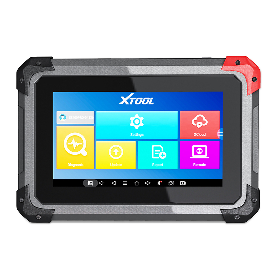
EZ400PRO Diagnosis System CHAPTER Ⅰ About EZ400PRO 1. Appearance 1.1. Front View 1.2. Back View... -
Page 4: Layout Of Ez400Pro Tablet
EZ400PRO Diagnosis System 2. Top View of EZ400PRO Tablet ① ② ③ ① MicroUSB:Battery charge or data synchronization with PC ②DB15 Port:Supports wired connection with car by the cable ③Power Button: Power on or power off 4. EZ400PRO Technical Parameters Operating System: Android Processor:Quad-core 1.6GHz Processor... -
Page 5: Chapter Ⅱ How To Use Ez400Pro
EZ400PRO Diagnosis System CHAPTER Ⅱ How to use EZ400PRO 1. EZ400PRO Activation 1.1. Please activate EZ400PRObefore you use it to test vehicles. . Input activation code, product serial number (each device will have a 1.2. Connect to WiFi first serial number and activation code), nickname (workshop’s name or user’s nickname), login account (can be your email address or cell phone number) and password, then system will remember it. -
Page 6: Ez400Pro Main Interface And Functional Buttons Descriptions
EZ400PRO Diagnosis System 2. EZ400PRO Main Interface and Functional Buttons Descriptions 2.1. Main Interface Tap on EZ400PRO application, the main interface and sub-menus shows up as below.▼ 2.2. Sub-menus and Function Buttons Function Buttons Descriptions Configures EZ400PROTablet perform diagnosis system. -
Page 7: Toolbar Function Buttons
Connect cables and EZ400PRO in following order: ①→②→③→④ b. Switch on the ignition and turn on EZ400PRO tablet, then tap on EZ400PRO application to test vehicles. (Shown as follows) EZ400PRO Mainframe ② Main Test Cable ③ OBDⅡ-16 ④ Vehicle 3.2. -
Page 8: Diagnosis
ECU and select the right menu according to the model number on the ECU label. 3.2.5. If users can not find the tested vehicle model or electronic control system in EZ400PRO test menu, they may need to update the software or consult Xtool technical service department 3.2.6. -
Page 9: Test Functions
EZ400PRO Diagnosis System entering European cars menu, selection for Asia means entering Asian cars menu, selection for America means entering American cars menu, selection for China means entering Chinese cars menu. Users also can input vehicle model to search. 4.2. Test Functions 4.2.1. -
Page 10: Read Ecu
Descriptions Returns to previous interface Print testing data Click it to record the data, click again to send your feedbacks to XTOOL after service center Record data feedback button as shown below, showing diagnostic software version and various information in the diagnostic process. -
Page 11: Read Dtcs
EZ400PRO Diagnosis System 4.4. Read DTCs Select Read Trouble Codes to read trouble codes stored in ECU. Screen will show the trouble code and its definition when read the trouble codes, shown as below. Tip: In the process of diagnosis, if the device shows “System is OK” or “No Trouble Code”, it... -
Page 12: Clear Dtcs
EZ400PRO Diagnosis System 4.5. Clear DTCs 4.5.1. Return to the previous step, select Clear DTCs to clear current and historical trouble codes memory in ECU. Performing this function will clear all the current and historical trouble codes. Make sure whether the trouble codes have been recorded before clearing, shown as below. - Page 13 EZ400PRO Diagnosis System Tips: Live Data is the important function for maintenance technicians to further diagnose the troubles. This function needs maintenance technicians very familiar with sensor data of each system, control signals and control modes, all which are the indispensable basis of using Live Data function for maintenance technicians.
-
Page 14: Special Functions
EZ400PRO Diagnosis System variations Display Modes There are two modes to view Live Data, users can choose optimum mode according their own needs and different parameter types. Dashboard Mode: Display parameters in the form of simulating instrument graphics. Graph Mode: Display parameters in the form of graph. -
Page 15: Actuatation/Ative/Components Test
EZ400PRO Diagnosis System 4.8. Actuatation/Ative/Components Test Test Conditions: Ignition on engine off If engine started or rotation speed signal recognized, actuating component diagnosing will be interrupted. In the process of actuating components diagnosis, single component will always be in the trigger status until the next component being activated. -
Page 16: Settings
EZ400PRO Diagnosis System show the menu of the actuating components that carry out action test, shown as below. Tip: Actuating Components Test performs function tests for parts of system actuating components. When performing this function, the diagnostic tool will take action test by simulating ECU signal to judge whether the actuating components or circuits are good. -
Page 17: Diagnostic Reports
EZ400PRO Diagnosis System Units: Select unit of measurement. Users can tick Metric or English measurement. System Settings: Android system setup, such as wireless, audio frequency, light sensation, etc. 6. Diagnostic Reports Diagnostic Reports is for checking the saved files, such as the report of Live Data or Trouble Codes or pictures generating in the process of diagnosis, users also can know what cars have been tested. -
Page 18: Pictures
Pictures are all the screen capture files in the diagnosis process. 6.3. Data Playback: Data Playback can check what cars have been tested and play recorded Live Data & freeze frame. 7. UPDATE EZ400PRO doesn’t need insert a card for updating, users only need to tap on EZ400PRO... -
Page 19: Xtool Cloud System(Coming Soon)
Xtool users in our forum, but can also access various online databases of maintenance and diagnostic skills and vehicle maintenance plans. -
Page 20: Chapter Ⅲ Diagnostic Link Connectors Of Different Vehicle Models
EZ400PRO Diagnosis System CHAPTER Ⅲ Diagnostic Link Connectors of Different Vehicle Models 1. Diagnostic Link Connectors Diagram of Some Vehicle Models *AUDI A6: the OBD plug is on the lower left side of the dashboard, we can use SMART OBDII-16 connector. - Page 21 EZ400PRO Diagnosis System *VW Bollywood 1.8: the OBD plug is below the console,we can use SMART OBDII-16 connector. *Benz S320,220 Chassis: the OBD plug is below the dashboard, we can use SMART OBDII-16 connector. *Benz C180: the OBD plug is in the right back side of engine room,we can use Benz-38...
- Page 22 EZ400PRO Diagnosis System *Benz 300SEL 140 chassis: the OBD plug is in the right side of the engine room,we can use Benz-38 connector. *GM Buick: the OBD plug is below the dashboard,we can use SMART OBDII-16 connector. *GM Buick GL8 : the OBD plug is below the dashboard,we can use SMART OBDII-16...
-
Page 23: Location Diagram Of Vehicle Diagnostic Link Connectors
EZ400PRO Diagnosis System *VW POLO: the OBD plug is below the dashboard; we can use SMART OBDII-16 connector. *BMW 735I: the OBD plug is in the left side of the engine room, we can use BMW-20 connector. *VW Passat B5: the OBD plug is behind the gearlever and beside the parking brake lever. It will appear when take away the cover. -
Page 24: Diagnostic Link Connectors Terminal Definition And Communication Protocols
EZ400PRO Diagnosis System Location diagram of pick-up truck diagnostic link connectors: Location diagram of utility vehicles diagnostic link connectors: Link diagram of small car diagnostic link connectors: NOTE: Each vehicle manufacturer may use additional pins to diagnose a variety of systems. - Page 25 EZ400PRO Diagnosis System Various pin definitions as follows: 1. Manufacturer definition 2. SAE J1850 bus positive 3. Manufacturer definition 4. Bodywork site 5. Signal site 6. ISO 15765-4 defined CAN high 7. ISO9141 and ISO14230 defined K line 8. Manufacturer definition 9.
Need help?
Do you have a question about the EZ400PRO and is the answer not in the manual?
Questions and answers