Table of Contents
Advertisement
Advertisement
Table of Contents

Related Manuals for Xtool PS90


Summary of Contents for Xtool PS90
- Page 1 PS90 Diagnosis System User Manual...
- Page 2 PS90 Diagnosis System Declaration 1. This manual is designed for the usage of PS90, applying to PS90 automotive diagnosis platform. No part of this manual can be reproduced, stored in a retrieval system or transmitted, in any form or by any means (electronic, mechanical, photocopying, recording, or otherwise), without the prior written permission of Xtool.
- Page 3 When reading the manual, please pay special attention to the words “Note”, “Caution” or “Warning”, read them carefully for appropriate operation. Xtool PS90 Diagnosis System main unit maintenance Avoid shaking or dismantling the unit as it may damage the internal components.
-
Page 4: Table Of Contents
2.2. Side View of PS90 Tablet ..................2 3. Layout of VCI Box ....................... 2 4. PS90 Technical Parameters..................3 CHAPTERⅡ How to Use the PS90 Diagnostic Computer ..........4 1. PS90 Activation ......................4 2. PS90 Main Interface and Functional Buttons Descriptions ........4 2.1. -
Page 5: Chapterⅰ About Ps90
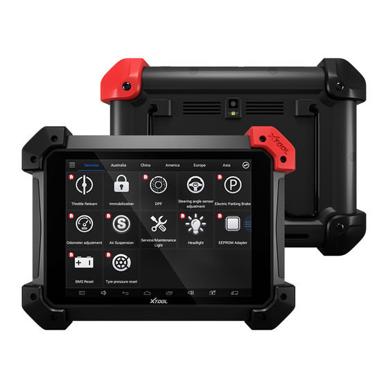
PS90 Diagnosis System CHAPTERⅠ About PS90 1. Appearance 1.1. Front View 1.2. Back View... -
Page 6: Layout Of Ps90 Tablet
PS90 Diagnosis System 2. Layout of PS90 Tablet 2.1. Top View of PS90 Tablet ① ② ③ ④ ① USB Type C Port: Data synchronization with PC. ② USB 3.0 Port: Supports wired connection with VCI kit. ③ HDMI Port: Compatible with HDMI TV. -
Page 7: Ps90 Technical Parameters
Bluetooth Indicator: Turns red when Bluetooth is not connected, turns blue when Bluetooth is successfully connected. Vehicle Indicator: Turns green when VCI box is connected with vehicle successfully. USB Indicator: turns green when PS90 tablet and VCI box are connected via USB cable. 4. PS90 Technical Parameters Operating System: Android 4.4.4... -
Page 8: Chapterⅱ How To Use The Ps90 Diagnostic Computer
CHAPTER Ⅱ How to Use the PS90 Diagnostic Computer 1. PS90 Activation 1.1. Please activate PS90 before you use it to test vehicles. And please connect WiFi first. 1.2. Input activation code, product serial number (each device will have a serial number and activation code), nickname (workshop’s name or user’s nickname),... -
Page 9: Sub-Menus And Function Buttons
Online Communication Platform for PS90 users. (English version is coming soon) Click UPDATE after PS90 is connected to internet, then you can download the latest diagnostic software directly to PS90. Users can view all the diagnostic reports and diagnostic data generated in the diagnosis process. -
Page 10: Vehicle Connection Diagnosis
OBD2 16 Pin connector or other connector, then plug into vehicles DLC port . c. Do not connect the PS90 Tablet to the VCI box with the USB cable. The Bluetooth will be paired automatically between PS90 tablet and VCI box. -
Page 11: Precautions Before Use
3.2.8. During long period of non-use, please disconnect the power and turn off the PS90 unit. 4.Diagnosis 4.1. Menu Options 4.1.1. After the VCI box is connected to the vehicle and paired with PS90 mainframe via wired or wireless connection, diagnosis can be performed. The diagnostic interface is as shown below:... -
Page 12: Test Functions
America will enter the American cars menu. Users also can input the vehicle model to search. 4.1.3. Besides the usual system diagnostic functions, XTOOL have also developed a series of special diagnostic functions for certain vehicles as follows: 4.2. - Page 13 Users can then enter the nature of the problem and any other relevant information and send the form to the Xtool engineering department.
-
Page 14: Read Ecu
PS90 Diagnosis System 4.3. Read ECU This function is used to read ECU version information, which is the equivalent of “System Identification” or “System Information” in some electronic control systems. This will allow you to read ECU related software and hardware versions, models and production date of diesel engine, part number, etc. -
Page 15: Clear Dtcs
PS90 Diagnosis System Tip: In the process of diagnosis, if the device shows “System is OK” or “No Trouble Code”, it indicates that the ECU has not detected a fault in any of the circuits that it monitors. If there is a fault which is not being recorded it may be that the fault is with a part of the system not under the control of ECU, such as a mechanical system fault. -
Page 16: Read Live Data
PS90 Diagnosis System 4.5.2. Click YES to confirm the operation, if the communication is normal, it will show “Trouble Codes Successfully Cleared” or “Trouble Codes Cleared”. Generally, users will need to re-read trouble codes after clearing them to confirm that the trouble codes have been cleared. - Page 17 PS90 Diagnosis System 5.Intake Air Show value a little higher than ℃ -40-150 Temperature ambient temperature 6.Battery Voltage 0-15 Idle speed: 11-13.5V 7.Injection closed-loop 0-1.99 correction Dependent on throttle position 8.Load 0-15 Engine warmed-up: 5-15 ℃ 9. Angle of Ignition ℃...
- Page 18 PS90 Diagnosis System...
-
Page 19: Special Function
PS90 Diagnosis System 4.7 Special Function Different vehicle makes and models will have different special functions available. 4.8. Actuation/Active Components Test Test Conditions: Ignition On engine Off. If the engine is started or an engine rotation speed signal is received, component actuation will be interrupted. -
Page 20: Setting
PS90 Diagnosis System 4.8.1. Return to Dynamic Diagnostic Data, enter Test Actuator and it will show the menu of the components that are available to actuate, shown below: Tip: Actuating Components Test performs function tests for system components. When performing this function, the diagnostic tool will simulate the ECU signal to enable the user to judge whether the actuating components or circuits are working correctly. - Page 21 PS90 Diagnosis System Units: Select unit of measurement. Users can select Metric or British Unit. Bluetooth: a. Select the VCI serial number and PS90 will pair with it automatically when running PS90 APP. b. How to pair with another device?
- Page 22 PS90 Diagnosis System Unpair the current device.
-
Page 23: Diagnostic Report
PS90 Diagnosis System Select the device you want to pair with PS90 and input the PIN code. System Settings: Android system setup, such as wireless, audio frequency, screen brightness, etc. 6. Diagnostic Report Diagnostic Report is used for viewing and printing the saved files, such as Live Data, Trouble Codes or pictures generated in the process of diagnosis, users also can view a record of which cars have been previously tested. -
Page 24: Pdf Files
PS90 Diagnosis System 6.1. PDF Files: 6.1.1. PDF files are the diagnostic reports of Live Data or Trouble Codes that have been saved during diagnosis. Entering PDF will allow you to view and print these reports. -
Page 25: Data Replay
PS90 Diagnosis System 6.1.2 Click PDF icon to generate PDF when you want to save the trouble code report 6.2. Data Replay: With Data Playback you can play back recorded Live Data & freeze frame data. 6.3. File Management: Pictures are all the screen capture files saved in the diagnosis process. -
Page 26: Update
PS90 Diagnosis System 7. UPDATE PS90 updates directly via the Internet using WiFi or wired connection. To access the update application open the PS90 application and click UPDATE , shown below: 8. Xtool Cloud System(English version is coming soon) The Xtool cloud service platform allows PS90 users to look up maintenance... -
Page 27: Chapter Ⅲ Examples Of Diagnostic Link Connector Locations
PS90 Diagnosis System CHAPTER Ⅲ Examples of Diagnostic Link Connector Locations. 1. Diagnostic Link Connectors Locations of Various Vehicle Models *AUDI A6: the OBD plug is on the lower left side of the dashboard, use SMART OBDII-16 connector. - Page 28 PS90 Diagnosis System *VW Bollywood 1.8: the OBD plug is below the console, use SMART OBDII-16 connector. *Benz S320,220 Chassis: the OBD plug is below the dashboard, use SMART OBDII-16 connector. *Benz C180: the OBD plug is on the left hand side of the engine bay, use Benz-38 connector.
- Page 29 PS90 Diagnosis System *GM Buick: the OBD plug is below the dashboard, use SMART OBDII-16 connector. *GM Buick GL8 : the OBD plug is below the dashboard, use SMART OBDII-16 connector. *VW POLO: the OBD plug is below the dashboard, use SMART OBDII-16 connector.
-
Page 30: Location Diagram Of Vehicle Diagnostic Link Connectors
PS90 Diagnosis System *VW Passat B5: the OBD plug is behind the gearlever and beside the parking brake lever. Lift the cover to access it. Use SMART OBDII-16 connector. 2. Location Diagram of Vehicle Diagnostic Link Connectors Location diagram of pick-up truck diagnostic link connectors:... - Page 31 PS90 Diagnosis System 1. Manufacturer definition 2. SAE J1850 bus positive 3. Manufacturer definition 4. Bodywork site 5. Signal site 6. ISO 15765-4 defined CAN high 7. ISO9141 and ISO14230 defined K line 8. Manufacturer definition 9. Manufacturer definition 10. SAE J1850 bus negative 11.
- Page 32 Shenzhen Xtooltech Co., Ltd Company address: 2nd Floor, Building No.2, Block 1, Excellence City, No.128, Zhongkang Road, Shangmeilin, Futian District, Shenzhen, China Factory address: 2/F, Building 12, Tangtou Third Industrial Zone, Shiyan Street, Baoan District, Shenzhen, China Service Hotline: 400-880-3086/ 0755-21670995 Email: marketing@xtooltech.com Fax: 0755-83461644...
Need help?
Do you have a question about the PS90 and is the answer not in the manual?
Questions and answers